Federation-less-federation of Network-virtualization Platforms Yasusi Kanada and Toshiaki Tarui
Kei Shiraishi
Hitachi, Ltd., Central Research Laboratory Yokohama, Japan {Yasusi.Kanada.yq, Toshiaki.Tarui.my}@hitachi.com
Hitachi, Ltd., Telecommunications & Network Systems Division Kawasaki, Japan
[email protected]
Abstract – A method for federating multiple networkvirtualization platforms by creating and managing slices (virtual networks) is proposed. A cross-domain slice can be created, deleted, or modified by sending a slice specification to the domain controller (network manager) of one domain. The specification is then propagated to other domains. Two challenges were addressed while this method was developed. The first challenge is to enable federation among multiple domains that do not support federation functions by only adding a few components without modification of the existing networkvirtualization-platform architecture. A domain-dependent specification of a slice, containing a pseudo virtual node that encloses a part of the slice specification in the other domains, is used, and this part is handled by a proxy node that represents another domain and a control component that implements a federation API to create a cross-domain slice. The second challenge is to enable manageable non-IP (arbitrary-format) data communication on a cross-domain slice. For an interdomain communication, underlay VLAN parameters including MAC addresses are negotiated in advance and data packets on a slice are tunneled between gateways in these domains. The proposed federation method was implemented on two networkvirtualization platforms, federation between two homogeneous domains was successfully demonstrated, federation performance was measured, and several issues on functional restrictions and implementation difficulty were found.
method was developed. The first challenge is to enable federation among multiple domains that do not support federation functions without modification of their existing network-virtualization platform architecture. Instead, a proxy node, which communicates with a controller component as a normal virtualization network node, is added to mediate between the domains. The slice structure of one domain is hidden from the slice specification of another domain. This “federation-less federation” reduces the hurdle of introducing a federation function into existing virtualization platforms; that is, it reduces the development cost and time and amount of resources required for developing federation functions as well as the number of bugs, degree of performance degradation, and number of service interruptions caused by deploying federation functions. The second challenge is to enable non-IP (arbitraryformat) data communication on a cross-domain slice. For an inter-domain communication, underlay VLAN parameters including VLAN ID and MAC addresses are negotiated in advance, and data packets on a slice are tunneled between gateways in these domains. Not only VLAN ID but also MAC addresses must be negotiated because no address resolution or correlation mechanism, such as the Address Resolution Protocol (ARP), is assumed when a non-IP (clean-slate) protocol is used for data communication. This federation method has been implemented on the VNode platform in a post-VNP project, and successful communication between two homogeneous domains was demonstrated. The rest of this paper is organized as follows. Section II summarizes the virtualization platform, the slice model, and the slice-creation and management method, which were previously developed. Section III describes the basic federation method, Sections IV outlines federating federation-less platforms, and Section V describes the federation-lessfederation architecture and the method of transforming slice specifications. Section VI describes the method of creating inter-domain links, which allows communication using nonIP protocols, and the data format used for inter-domain data communication. Sections VII to VIII describe the implementation and evaluation of the federation method as well as related work, and Section IX concludes this paper.
I. INTRODUCTION In Japan, several projects targeting “new-generation networks” (NwGN) have been conducted [Aoy 09] [AKA 10]. These projects aim to develop new network protocols and architectures (i.e., the “clean slate” approach [Fel 07]) as well as various applications that are difficult to run on internet protocols (IPs) but work well on NwGNs. The Virtualization Node Project (VNP) [Nak 10] and its successive projects aim to develop network-virtualization technology and virtualization nodes (VNodes). The goal of these projects are to develop an environment where multiple slices (or virtual networks) with independently designed NwGN architectures and functions using arbitrary-format (non-IP and non-Ethernet) packets run concurrently, but are logically isolated, on a physical network. The virtualization platform developed by VNP [Nak 12b][Nak 12a] have been deployed in the testbed network JGN-X [Pan 11] for designing, deploying, and testing new network services in Japan. In this study, a method for federating virtualization platforms is proposed. This method enables both homogeneous and heterogeneous federation; that is, creating a slice across two or more network-virtualization platforms of the same or different type. Slices contain virtual nodes and virtual links, so both virtual-node and -link resources should be managed. Especially, the virtual links between the platforms, which might not be managed by the platforms, should be managed. Two challenges were addressed while this federation
II. VIRTUALIZATION PLATFORM AND SLICE MODEL This section explains network virtualization, the virtualization platform, the structure of slices, and the basic slicecreation and management method developed in VNP. A. Network Virtualization When many users and systems share a limited amount of resources on computers or networks, virtualization technol1
ogy creates the illusion that each user or system possesses their own resources. Concerning networks, wide-area networks (WANs) are virtualized by using virtual private networks (VPNs). When VPNs are used, a physical network can be shared by multiple organizations, and these organizations can securely and conveniently use VPNs in the same way as virtual leased lines. Nowadays, networks in data centers are virtualized by using VLANs, while servers are virtualized by using VMs. Many research projects on programmable virtualization networks have been carried out, and many models, including PlanetLab [Pet 02][Tur 07], Virtual Network Infrastructure (VINI) [Bav 06], Global Environment for Network Infrastructure (GENI) [Due 12], and Genesis [Kou 01], have been proposed. In VNP, Nakao et al. [Nak 12b][Nak 10] developed a VNode architecture and platform that make it possible to build programmable virtual-network environments in which slices are isolated logically, securely, and in terms of performance (QoS) from one another [Kan 12a]. In these environments, new-generation network protocols can be developed without disrupting the other slices.
essing packets with an arbitrary format. It is generated by slicing and abstracting physical computational resources. • Virtual link (or link sliver) is a link resource between two virtual nodes both IP and non-IP protocols can be used on this link. It is mapped on a physical link between two VNodes. It is generated by slicing and abstracting physical network resources such as bandwidth. A slice developer describes a slice specification in XML. However, each slice specification is expressed as a diagram hereafter. A specification of a slice, named S, with three virtual nodes (VN1, VN2, and VN3) and three virtual links (VL12, VL13, and VL23) is shown in Figure 2(a). The virtual nodes are mapped to VNodes (N1, N2, and N3). If the description of the mapping between virtual and physical nodes is omitted, the DC determines the mapping instead. This mapping problem, which is called the virtual-network embedding problem, has been widely studied (e.g., [Zhu 06] [Cho 10][Zah 10]). The virtual-node specifications in a slice specification contains URLs of the VM images, but the slice developers can load programs into the VMs and run them by using secure shell (ssh) commands after loading and starting the VMs. Virtual links are implemented by using a tunneling protocol such as GRE. The tunnels may bypass physical nodes. Slice structures, therefore, do not necessarily depend on the physical structure of the network. The slice developer can program virtual nodes by specifying the URL of a VM image or a fast-path program to be loaded.
B. Structure of VNode Platform Each VNode platform domain (managed by a platform operator) is managed by a domain controller (DC), and each domain has two types of nodes: VNode and gateway (see Figure 1). VNode forwards packets on the platform. A domain may contain conventional routers or switches that do not have virtualization functions. VNodes are connected by tunnels using a protocol such as Generic Routing Encapsulation (GRE) [Far 00]. Therefore, a slice is neither constrained by the topology of the physical network nor by the specific functions of these nodes. A VNode can operate as a router or a switch for platform packets, so it can be deployed in conventional networks. Each VNode consists of the following three components. Programmer processes packets like a router or a switch on each slice. Slice developers (or slice operators) can inject programs into programmers. Redirector forwards (redirect) packets from another VNode to a programmer and forward packets from a programmer to another VNode. VNode manager manages the VNode according to instructions from the DC.
D. Basic Slice-Operation-And-Management Method The DC of a domain receives a slice-operation message with whole or part of a slice specification from the slice developer (see Figure 2). The DC distributes the message to each VNode in the domain. In a VNode, the VNode manager receives the specification and sends a part of the slice specification to the programmer and another part to the redirector: the programmer receives information required for virtual-node configuration, and the redirector receives the information required for virtual-link configuration. For example, in the case shown in Figure 2, the specification of VN1 is deployed to the programmer in N1, and the specification of VL12 is deployed to the redirectors in N1 and N2. The detailed information in virtual nodes and links are managed by VNode managers, programmers, and redirectors, but not by the DC (which is not responsible for the details).
C. Structure of Slices In the virtual-network model developed by VNP, a virtual network (or a collection of resources in a virtual network) is called a slice, which consists of the following two types of components (see Figure 2(a)) [Nak 12b][Nak 10].
III. BASIC SLICE-FEDERATION METHOD The federation functions provided by the slice-federation method connect two or more domains of the same or
• Virtual node (or node sliver) represents a computational resource in a VNode. It is used for node control or procVNode
DC
VNM P
R VNode
User’s PC/VM
DC: VNode: VNM: R: P:
Gateway
VNode
Slice specification Slice S VN1* … N1** VL13† VL12† VN2* … N2** VL23† VN3* … N3**
Domain controller Virtualization node VNode manager Redirector Programmer
VNode
IP router
VNode
Gateway
Operation
Virtualization platform (domain)
(creation, modification, etc.)
* VN1, VN2, VN3: Virtual nodes. ** N1, N2, N3: VNodes. † VL12, VL13, VL23: Virtual links.
User’s PC/VM
Domain controller
VNode N2
VNode N1
VN1
VL12
VNode N3
VN2
VL23
VNode N4 VL13 VN3
(a) Slice specification (b) Slice operation (creation, etc.) Figure 2. Single-domain slice specification and operation
Figure 1. Physical structure of virtualization platform 2
Slice specification Slice S VN1
… N11
VL14 VN2
… N12
Domain A Operation
… N21
VNode N11
VN4
… N22
VNode
Domain Controller
(Slice Exchange Point, SEP)
(creation, modification, etc.)
VL23 VN3
Domain B Federation API
Domain Controller
VN1 VNode N12
VL14
VN2
VL23
VN4
VNode N21
VN3 VNode N22
VNode
(a) Basic federation method 1. Resource discovery function: Cross-domain discovery of computational resources available in virtual nodes and link resources available between virtual nodes. The API finds resources from known domains, i.e., known gatekeepers. No function for discovering DCs, DPNs, gateways, and gatekeepers is included. 2. Slice handling function: a) Creation of a slice among multiple domains, b) Slice modification, i.e., addition/removal of virtual nodes or links in a federated domain or cross-domain virtual links, c) Deletion of a slice among domains. 3. Query on statistics and manifests: a) Query on slice (and platform) statistics such as number of packets counted in a virtual link, b) Query on manifests, i.e., bottom-up parameters such as virtual-node host-names or addresses.
tion API. The federation of two domains is shown in Figure 3(a). If three or more domains are federated, the messaging pattern is more complicated. A four-domain example is shown in Figure 3(c). In this figure, domain A sends federation messages through the API (APIs) between A and B and between A and C. Domain C forwards the message to domain D.
IV. CONCEPTUAL OUTLINE OF FEDERATIONLESS FEDERATION The federation between two domains without federation functions is conceptually outlined as follows (see Figure 4). A virtualization platform without federation functions does not have a concept of “other domain” because the “own domain” is the only domain. Therefore, (b) Functions of the federation API the other domain part of the cross-domain slice Federation specification must belong to the own domain. Domain B API This means that the other domain is a subDomain A Federation Slice specification Federation domain of the own domain. Because a part of API API Domain C Domain D the slice in the other domain is to be managed only by the DC in the other domain and (c) More complicated messaging pattern duplicated management of the part must be Figure 3. Federation API and cross-domain slice creation avoided, this part must be hidden, i.e., encapsulated, from the DC in the own domain. different type of virtualization platform, including VNode In a slice specification, the only way to express the set of platforms, GENI-based platforms [Pat 10], and so on. The domains are federated by using a set of APIs called virtual nodes and virtual links in a sub-domain is to use a federation APIs (see Figure 3(a) and (b)). The federation virtual node. This node belongs to a pseudo VNode, which APIs should be standardized interfaces supported by various does not have network-node functions, such as routing or types of virtualization platforms. Each API basically switching, because it only represents and delegates the other consists of simple pair of a request and a reply. In the post- domain. The pseudo VNode is, thus, called a domain proxy VNP project, the place where the federation APIs work is node (DPN). Although a DPN is not a real network node, a DPN mimics a VNode; that is, it provides the same API as a called the slice exchange point (SEP). Many types of federation functions, such as listed in VNode and the DC can manage it by the same method. The Figure 3(b), are provided. However, the focus in this paper DC maps a pseudo virtual node (PVN) on a DPN by using is not the federation functions themselves, but it is the the same way as for a normal virtual node, and the PVN transformation of slice specifications, which is common to must contain a part of the slice specification for the other all the federation functions. Only creation function is, thus, domain (B) as a substructure. This means that the DPN conceptually contains an image of the other domain. used for explanation in this paper. Similarly, if the other domain does not have federation It is assumed that a slice-operation message with a slice specification is sent to the DC of a domain (domain A in functions either, it must have a DPN that contains the image Figure 3(a)) at first, and a copy of the specification is for- of the own domain (A) and the PVN in a part of the slice warded to the DC of the other domain (domain B) through specification of the other domain is mapped to a DPN that the federation API. No clearing house, or hub, is used for represents the own domain. Therefore, conceptually, as this communication. The slice specification shown in shown in Figure 4, the image contained in the DPN Figure 3 consists of four virtual nodes and four virtual links. recursively contains the domain images. The slice specificaTwo virtual nodes (VN1 and VN2) belong to domain A, and tions exchanged through the federation API reflect the the other virtual nodes belong to domain B. Two of the four above conceptual structure. However, this static recursion virtual links (VL14 and VL23) are inter-domain links. may not cause a message loop in federation. Because inter-domain links exist, these domains cannot be managed independently; in other words, the inter-domain Domain A Domain B links must be managed in relation to both domains. Domain proxy node Domain proxy node Federation In a slice creation, VN1 and VN2 are created and man(Subdomain) (Subdomain) aged by the DC in domain A, and VN3 and VN4 are created and managed by the DC in domain B. Although the virtual links within a domain are managed solely by the DC in the domain, the inter-domain links are cooperatively created and Image of the other Image of own Image of the other Image of own domain domain domain domain managed by two DCs in both domains. The information required for this cooperation is exchanged using the federaFigure 4. Conceptual outline of federation-less federation 3
It is assumed that the DC is not responsible for detailed information enclosed in a virtual node in the own domain; in a similar manner, it is not responsible for (does not manage) detailed information in PVNs (i.e., in the other domain).
control. A gatekeeper (gatekeeper 1 in Figure 5) receives the slice specification, transforms it to an API-based format, and forwards it to the gatekeeper of the other domain (gatekeeper 2). The API between the gatekeepers is the federation API. The slice specification sent from one gatekeeper to the other must be syntactically symmetric about the domain border because the two domains are symmetric. A gatekeeper also configures the gateway for inter-domain links through the gatewaycontrol interface (i.e., the control interface of a gateway). The word “gatekeeper” comes from the terminology of ITU-T H.323, although there are differences in its role.
V. FEDERATION ARCHITECTURE AND TRANSFORMATION OF SLICE SPECIFICATIONS The proposed federation architecture, the transformation process of a slice specification, and a method of message loop avoidance are described in this section. A. Architecture The proposed federation architecture is shown in Figure 5. In this figure, both domains, D1 and D2, are VNode platforms. However, this architecture can be applied to heterogeneous federation; that is, even when domain D2 is a different type of platform, there is no need to modify the left half of this figure, although the detailed message contents and federation sequence may have to be changed. The following three physical components are added to the domain as federation interfaces (i.e., SEPs).
• Gateway (federation gateway) is a network node that has a function for data conversion from the internal format in the own domain to an intermediate format between the federated domains. A gateway (gateway 1) sends packets to the other gateway (gateway 2) toward the other domain, and it receives packets for the own domain from the other gateway. In the case of federating two domains, each domain has a DPN, a gatekeeper, and one or more gateways. In contrast, in the case of federating N domains, each domain may have N (or less) DPNs, one to N gatekeepers, and one to N gateways. These three types of nodes may therefore be separately deployed because of flexibility of design and implementation, and performance.
• Domain proxy node (DPN) is a pseudo VNode that receives a whole slice specification (or the specification of the PVN) from the DC of the own domain. The DPN receives a slice specification containing the PVN, which is mapped to the DPN. This virtual-node contains part of the slice in the other domain. Because the slice structure is symmetric about the domain border, the slice specification described by the slice developer should also be syntactically symmetric. However, the slice specification acceptable by DPN and DC is syntactically asymmetric (that is, the virtual nodes in the other domain are enclosed but those in the own domain are not enclosed) because, in the PVN, the virtual nodes in the own domain must be bare (i.e., managed by DC), and those in the other domain must be enclosed (i.e., not managed by DC). • Gatekeeper is a server for federation management and Slice specification S1 Slice specification Sf Slice specification S2 Slice S
Slice S
VN1* … N11** VL14 †† VN2* … N12**
Slice S
VN1* … N11**
VN1* … N11**
*VN1, VN2, VN3, VN4, PV1, PV2: Virtual nodes.
VN2* … N12**
VN2* … N12**
** N11, N12, N21, N22: VNodes.
Domain D1
VL23 ††
VirtualNode PV2*
VirtualNode PV1*
VN3* … N21**
VN3* … N21**
VN3* … N21**
VN4* … N22**
VL14†† VN4* … N22**
VN4* … N22** … P11†
Operation (creation, modification, etc.)
… P21†
VL23 ††
Domain D2
P21: DPN (domain proxy nodes)
††
VL14, VL23: Cross-domain virtual links.
‡ Gateway
(1)
Control Interface
Domain D1 Gatekeeper 1
Domain controller Common API
† P11,
(2)
(4)
×(8)
Domain D2 Gatekeeper 2
(3) Federation (7)
(5)
Domain controller
(6)
Common API
API
Domain proxy node P11
VNode N11 VNode
VNode N12
GCI‡ GCI‡
Domain proxy node P21
GateGateway 1 way 2 Data exchange protocol
VNode N21 VNode N22
VNode
(GRE,VLAN-based tunneling, etc.)
Figure 5. Federation architecture and transformation of slice specification 4
B. Transformation of Slice Specification The forms of slice specification and the transformation process are also shown in Figure 5. In a slice specification given to the DC, the PVN encloses the part of the slice for the other domain. In slice specification S1, PV1 encloses this part. This enclosure, i.e., PV1, is the border of responsibility. Because the DC does not have federation functions, this domain-dependent form (S1) must be used for creating a cross-domain slice. However, if an appropriate preprocessor is supplied, the slice developer can use a domain-independent form, i.e., the slice Sf; in other words, the preprocessor can translate the domain-independent form to the domain-dependent form. The original slice specification (S1) is sent to the DC (step 1 in Figure 5) at first, and the DC distributes it to all the VNodes in the own domain including the DPN, which is manually registered to the DC (step 2). Although the whole slice specification is sent to each VNode in the VNode platform, only the PVN (PV1) may be sent to the DPN (P11) in general. However, the complete specification would probably work when an error or exception occurs. If only partial slice information is available in each domain, the slice developer must collect and combine pieces of operation-and-management information to find the actual problem, such as a bug, by oneself instead of using an automated information collector. The DPN sends the specification to the gatekeeper, which is manually registered to the DPN (step 3), and the gatekeeper transforms it to the domain-independent form Sf. This specification is syntactically symmetric about the domain border. In this specification, the virtual nodes of each domain are enclosed in an envelope labeled by the domain name. In this figure, the envelopes are labeled as domains “D1” and “D2”.
The slice specification is sent to the other domain (step 4). The federation API (i.e., SEP) may have a discovery function of gatekeepers. However, gatekeepers of other domains may also be manually registered to a gatekeeper. Gatekeeper 2 transforms it to a domain-dependent form of Domain D2, and sends it to the DC (step 5). In this specification (S2), a PVN called “PV2” encloses the part of the slice (of D1). This enclosure, i.e., PV2, is the border of responsibility. PV2 is mapped to the DPN labeled “P21” in gatekeeper 2. The DC of domain D2 distributes the specification to all the VNodes in domain D2 including P21 (step 6). P21 sends the specification to the gatekeeper (step 7) in the same way that the P11 sends it to gatekeeper 1. Gatekeeper 2 behaves differently from gatekeeper 1 in the original domain. If a slice specification is received by the current domain (D2) at first, the gatekeeper forwards it to the other domain (D1). However, if it is received by the other domain, an infinite loop may occur. In spite of this risk, this slice specification must contain information on the other domain because this information is required for interfacing the domains, i.e., for completing inter-domain links. To avoid this loop, the gatekeeper must reject sending it to the original domain (step 8) (or the gatekeeper in the other domain (D1) must reject the message). The available methods to avoid this loop are described in the next subsection. Note that the proposed federation method may have two problems: one concerning scalability and one concerning security and privacy. The first problem is that it may take too much time or resources to parse the XML of the slice specification because PVN may contain a large and complicated structure to be parsed and analyzed. However, because neither the DC nor the DPN have to parse it, this scalability problem can be avoided. The parsing and analyzing overhead can thus be avoided, for example, by encoding the structure by a scheme such as Base64. The second problem is that the DC or the DPN may leak domain internal information contained in the other-domain part of a slice specification. This problem can be solved by encrypting the information. For example, the content of PV1 in the slice S1, which belongs to domain D2, can be encrypted before it is given to the DC of domain D1, and this content can be decrypted by gatekeeper 2. In addition, the content of PV2 in the slice S2, which belongs to domain D1, can be encrypted by gatekeeper 1. Alternatively, the problem can be solved by removing the internal information of D1 by gatekeeper 1 before sending it to the other domain. In both cases, PV2 becomes a black box. Both contents of envelopes labeled D1 and D2 in the slice Sf between two gatekeepers are encrypted.
specification. The slice identifier contained in the message may be used for this identification. However, this problem may occur not only in a slice-creation message but also in modification or query messages. Two or more slice modification or query messages that specify the same slice may be designated by a slice developer simultaneously. The message identity must therefore be recognized by using more powerful means such as unique request identifiers. In addition, the following methods may be used in combination with the above basic method for avoiding unexpected events caused by errors or bugs. One method is marking. A gatekeeper can mark messages that come from other domains. This method is probably useful only in federation of two domains because three or more types of messages, which must be distinguished when three or more domains exist, cannot be distinguished by this method. Another method uses TTL (time-to-live). The management system can add a TTL to a message when it first receives the message from outside of the system. This method is more powerful than marking. However, it still fails when the number of domains that are linearly chained is larger than the initial value of TTL. These two methods are therefore useful only as a backup of the method based on identity. VI. MANAGEABLE INTER-DOMAIN LINKS FOR NON-IP COMMUNICATION A cross-domain slice specification usually contains interdomain virtual links. Several issues on these links and their solutions are explained. To enable manageable inter-domain non-IP communication, both issues must be solved. 1. Protocol and data format used for inter-domain data communication (Data-plane issue) The protocol and the data format used for platform (underlay) communication must be selected in consideration of available hardware and software. The function of a network between two domains may be restricted; only a limited set of protocols may be available. However, to exchange virtualized packets, a type of tunneling protocol is required. If the network is IP-based, GRE is a candidate, and if the network is Ethernet, VLAN-based “tunneling” may be used. We assume the latter is used. 2. Method of setting up the underlay link that corresponds to the virtual link (Control-plane issue) To set up an underlay inter-domain link, the facing domains must exchange necessary parameters such as IP addresses (and GRE keys) in the case of an IP-based network. These parameters are exchanged between the domains by the gatekeepers. If the network between the domains is managed by another operator, a negotiation with its manager may be required. When IP-over-VLAN is used (i.e., IP is used on the slice and VLAN is used on the platform), VLAN ID must be exchanged but MAC addresses are not necessarily exchanged by the gatekeepers because they can be obtained by using ARP. However, if “X over VLAN” is used (i.e., a non-IP protocol, which might have no “address” concept, is used on the slice and VLAN is used on the platform), MAC addresses must be exchanged in addition to VLAN ID because no address resolution or correlation mechanism such as ARP is assumed to be available.
C. Message Loop Avoidance As described in the previous subsection, inter-domain messaging may cause an infinite loop. Several methods to avoid this loop are described here. A message loop is caused by the nature of federation-less federation, i.e., conceptual recursion, described in Section IV. The message pattern described in the previous subsection is the simplest one. However, if there are three or more domains, various loop patterns may occur. The basic method for avoiding a loop is to identify a slice specification and not to forward or to process such a 5
Node N12
DPN P11
Gate- Federation GateAPI keeper 1 keeper 2
Gateway Control Interface (GCI)
Gateway1 conv VN1 IP VL14i1 IP MAC
Domain D1
DPN P21
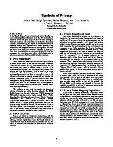
be bypassed. Figure 6(b) shows the data format when an arbitrary (non-IP or IP) packet format is used on the slice. Network processors can be used for high-performance (10Gbps) data conversions in gateways.
Node N22
Gateway Control Interface (GCI)
VL14e
Gateway2 conv VN4 MAC IP VL14i2 IP
Cross-domain network
VII. IMPLEMENTATION AND EVALUATION The federation functions were partially implemented on the VNode platform and evaluated by connecting two domains as described in the following. The functions of DPN, gatekeeper, and gateway are implemented as a modified version of a VNode called “network accommodation equipment” (NACE) [Kan 12c]. NACE was originally designed for accommodating a non-virtualized network in a slice. This function is here extended to cross-domain federation. The slice specification described in Figure 7 and visualized in Figure 8(a) is used for the evaluation. (Note that in Figure 7 several parts of the specification are omitted and several identifiers are renamed for understandability.) The specification contains inter- and intra-domain virtual links, a virtual node VN0 that contains a slow-path VM, a virtual access gateway AG00 for terminal users (which is created in the gateway explained in Section II B), and a PVN named PV1 (which contains a virtual node named VN1 that contains another slow-path VM and is assigned to a DPN named P11forD2). The specification of PV1 is sent to P11forD2, and a part of the specification is converted to the specification for domain D2 visualized in Figure 8(b). Several virtual nodes,
Domain D2
(a) Data-link structure IP
GRE
Any frame
MAC VLAN
Any frame
IP
GRE
Any frame
(b) Data communication using arbitrary packet-format Figure 6. Inter-domain data-link structure and data communication The method of the link creation, which is the most important link operation, is outlined below. In slice S1 in Figure 5, there are two inter-domain virtual links, VL14 and VL23. A link that corresponds to each inter-domain virtual link is created by stitching three sections (see Figure 6(a)). Because two or three different protocols may be used in the two domains and the network in between, the link is divided into three sections. In the case of VL14, VL14i1 is the domain-D1-internal section, VL14e is the inter-domain section, and VL14i2 is the domain-D2-internal section. Both end points of each section of the links have their own addresses; that is, they are independent. In the control plane, node N12 and the gateway in domain D1 (gateway 1) negotiate the parameters for VL14i1 when the domain-D1 part of the slice is created [Kan 12b]. The parameters for VL14i2 are negotiated by using the same method. As described in Figure 5 (step 4 and its response), however, the gatekeepers negotiate the parameters for VL14e, including the VLAN ID, the MAC addresses, and possibly the tunneling method. If the link resource (such as bandwidth) between two domains is managed by a network operator other than the operators of the two domains, the gatekeeper(s) must negotiate the resource with the operator. The link may even cross firewalls between the domains. In the implementation, GRE tunneling is used for VL14i1 and VL14i2, and VLAN is used for VL14e. Available protocols and formats will be added in future. No management system in the network between the domains is assumed. Both end points of VL14i1 and VL14i2 have IP addresses for the GRE tunnels, and both end points of VL14e have MAC addresses for the inter-domain VLAN communication. VL14i1 is generated by an intra-domain signaling (using GMPLS between VNode Managers), which is a normal signaling for generating an intra-domain virtual link, between the VNode Managers of N12 and P11. The VNode managers negotiate the GRE key and the IP addresses for both end points of VL14i1. VL14i2 is generated by the same method. VL14e is generated by messaging through the federation API. The gatekeepers negotiate the VLAN ID and the MAC addresses for both end points of VL14e. The gatekeepers send commands to the gateways for setting up the link. In the data plane, the data conversion between VL14i1 and VL14e is performed in gateway 1, and that between VL14e and VL14i2 is performed in gateway 2. If no data conversion is required, that is, the same protocol and data format are used on both sides of a gateway, the gateway can
… … … … … …