Apr 10, 2009 - a linear equation involving the packets. ... is not clear which linear combination the sender should ... have feedback in a system with network coding, what is the best ... their uncertainty can be resolved using only packets with.
1
Feedback-based online network coding
arXiv:0904.1730v1 [cs.NI] 10 Apr 2009
Jay Kumar Sundararajan, Student Member, IEEE, Devavrat Shah, Member, IEEE, Muriel M´edard, Fellow, IEEE
Abstract—Current approaches to the practical implementation of network coding are batch-based, and often do not use feedback, except possibly to signal completion of a file download. In this paper, the various benefits of using feedback in a network coded system are studied. It is shown that network coding can be performed in a completely online manner, without the need for batches or generations, and that such online operation does not affect the throughput. Although these ideas are presented in a single-hop packet erasure broadcast setting, they naturally extend to more general lossy networks which employ network coding in the presence of feedback. The impact of feedback on queue size at the sender and decoding delay at the receivers is studied. Strategies for adaptive coding based on feedback are presented, with the goal of minimizing the queue size and delay. The asymptotic behavior of these metrics is characterized, in the limit of the traffic load approaching capacity. Different notions of decoding delay are considered, including an order-sensitive notion which assumes that packets are useful only when delivered in order. Our work may be viewed as a natural extension of Automatic Repeat reQuest (ARQ) schemes to coded networks. Index Terms—Network Coding, Decoding Delay, ARQ
I. I NTRODUCTION This paper is a step towards low-delay, highthroughput solutions based on network coding, for realtime data streaming applications over a packet erasure network. In particular, it considers the role of feedback for queue management and delay control in such systems. A. Background Reliable communication over a network of packet erasure channels is a well studied problem. Several solutions have been proposed, especially in the case when there is no feedback. We compare below, three The authors are with the Department of Electrical Engineering and Computer Science, at the Massachusetts Institute of Technology, Cambridge, MA 02139. Email: {jaykumar, devavrat, medard}@mit.edu Manuscript received ; revised . Parts of this work were presented at IEEE ITW 2007, IEEE ISIT 2008 and ISITA 2008.
such approaches – digital fountain codes, random linear network coding and priority encoding transmission. 1. Digital fountain codes: The digital fountain codes ([1], [2]) constitute a well-known approach to this problem. From a block of k transmit packets, the sender generates random linear combinations in such a way that the receiver can, with high probability, decode the block once it receives any set of slightly more than k linear combinations. This approach has low complexity and requires no feedback, except to signal successful decoding of the block. However, fountain codes are designed for a point-to-point erasure channel and in their original form, do not extend readily to a network setting. Consider a two-link tandem network. An end-to-end fountain code with simple forwarding at the middle node will result in throughput loss. If the middle node chooses to decode and re-encode an entire block, the scheme will be sub-optimal in terms of delay, as pointed out by [3]. In this sense, the fountain code approach is not composable across links. For the special case of tree networks, there has been some recent work on composing fountain codes across links by enabling the middle node to re-encode even before decoding the entire block [4]. 2. Random linear network coding: Network coding was originally introduced for the case of error-free networks with specified link capacities ([5], [6]), and was extended to the case of erasure networks [7]. In contrast to fountain codes, the random linear network coding solution of [8] does not require decoding at intermediate nodes and can be applied in any network. Each node transmits a random linear combination of all coded packets it has received so far. This solution ensures that with high probability, the transmitted packet will have what we call the innovation guarantee property, i.e., it will be innovative1 to every receiver that receives it successfully, except if the receiver already knows as much as the sender. Thus, every successful reception will bring a unit of new information. In [8], this scheme is shown to achieve capacity for the case of a multicast session. 1
An innovative packet is a linear combination of packets which is linearly independent of previously received linear combinations, and thus conveys new information.
2
An important problem with both fountain codes and random linear network coding is that although they are rateless, the encoding operation is performed on a block (or generation) of packets. This means that in general, there is no guarantee that the receiver will be able to extract and pass on to higher layers, any of the original packets from the coded packets till the entire block has been received. This leads to a decoding delay. Such a decoding delay is not a problem if the higher layers will anyway use a block only as a whole (e.g., file download). This corresponds to traditional approaches in information theory where the message is assumed to be useful only as a whole. No incentive is placed on decoding “a part of the message” using a part of the codeword. However, many applications today involve broadcasting a continuous stream of packets in real-time (e.g., video streaming). Sources generate a stream of messages which have an intrinsic temporal ordering. In such cases, playback is possible only till the point up to which all packets have been recovered, which we call the front of contiguous knowledge. Thus, there is incentive to decode the older messages earlier, as this will reduce the playback latency. The above schemes would segment the stream into blocks and process one block at a time. Block sizes will have to be large to ensure high throughput. However, if playback can begin only after receiving a full block, then large blocks will imply a large delay. This raises an interesting question: can we code in such a way that playback can begin even before the full block is received? In other words, we are more interested in packet delay than block delay. These issues have been studied using various approaches by [9], [10] and [11] in a point-to-point setting. However, in a network setting, the problem is not well understood. Moreover, these works do not consider the queue management aspects of the problem. In related work, [12] and [13] address the question of how many original packets are revealed before the whole block is decoded in a fountain code setting. However, performance may depend on not only how much data reaches the receiver in a given time, but also which part of the data. For instance, playback delay depends on not just the number of original packets that are recovered, but also the order in which they are recovered. 3. Priority encoding transmission: The scheme proposed in [14], known as priority encoding transmission (PET), addresses this problem by proposing a code for the erasure channel that ensures that a receiver will receive the first (or highest priority) i messages using the first ki coded packets, where ki increases with decreasing priority. In [15], [16], this is extended to systems that perform network coding. A concatenated
network coding scheme is proposed in [16], with a delaymitigating pre-coding stage. This scheme guarantees that the kth innovative reception will enable the receiver to decode the kth message. In such schemes however, the ability to decode messages in order requires a reduction in throughput because of the pre-coding stage. B. Motivation The main motivation for our current work is that the availability of feedback brings the hope of simultaneously achieving the best possible throughput along with minimal packet delay and queue size. Reliable communication over a point-to-point packet erasure channel with full feedback can be achieved using the Automatic Repeat reQuest (ARQ) scheme – whenever a packet gets erased, the sender retransmits it. Every successful reception conveys a new packet, implying throughput optimality. Moreover, this new packet is always the next unknown packet, which implies the lowest possible packet delay. Since there is feedback, the sender never stores anything the receiver already knows, implying optimal queue size. Thus, this simple scheme simultaneously achieves the optimal throughput along with minimal delay and queue size. Moreover, the scheme is completely online and not block-based. However, if we go beyond a single point-to-point link, ARQ is not sufficient in general. Coding across packets is necessary to achieve optimal throughput, even if we allow acknowledgments. For instance, in the network coding context, link-by-link ARQ cannot achieve the multicast capacity of the butterfly network from network coding literature [5]. Similarly, ARQ is sub-optimal for broadcast-mode links because retransmitting a packet that some receivers did not get is wasteful for the others that already have it. In contrast, network coding achieves the multicast capacity of any network and also readily extends to networks with broadcast-mode links. Thus, in such situations, coding is indispensable from a throughput perspective. This leads to the question – how to combine the benefits of ARQ and network coding? The goal is to extend ARQ’s desirable properties in the point-to-point context, to systems that require coding across packets. The problem with applying ARQ to a coded system is that a new reception may not always reveal the next unknown packet to the receiver. Instead, it may bring in a linear equation involving the packets. In conventional ARQ, upon receiving an ACK, the sender drops the ACKed packet and transmits the next one. But in a coded system, upon receiving an ACK for a linear equation, it is not clear which linear combination the sender should
3
pick for its next transmission to obtain the best system performance. This is important because, if the receiver has to collect many equations before it can decode the unknowns involved, this could lead to a large decoding delay. A related question is: upon receiving the ACK for a linear equation, which packet can be excluded from future coding, i.e., which packet can be dropped from the sender’s queue? If packets arrive at the sender according to some stochastic process, (as in [17], [18]) and links are lossy (as in [7], [8]), then the queue management aspect of the problem also becomes important. One option is to drop packets that all receivers have decoded, as this would not affect the reliability. However, storing all undecoded packets may be suboptimal. Consider a situation where the sender has n packets p1 , p2 . . . , pn , and all receivers have received (n−1) linear combinations: (p1 +p2 ), (p2 +p3 ), . . . , (pn−1 +pn ). A drop-when-decoded scheme will not allow the sender to drop any packet, since no packet can be decoded by any receiver yet. However, the backlog in the amount of information, also called the virtual queue ([17], [18]), has a size of just 1. We ideally want the physical queue to track the virtual queue in size. (Indeed, in this example, it would be sufficient if the sender stores any one pi in order to ensure reliable delivery.) These issues motivate the following questions – if we have feedback in a system with network coding, what is the best possible tradeoff between throughput, delay and queue size? In particular, how close can we get to the performance of ARQ for the point-to-point case? These are the questions we address in this paper. II. O UR CONTRIBUTION In this paper, we show that by proper use of feedback, it is possible to perform network coding in a completely online manner similar to ARQ schemes, without the need for a block-based approach. We study the benefits of feedback in a coded network in terms of the following two aspects – queue management and decoding delay. A. Queue management Note: In this work, we treat packets as vectors over a finite field. We restrict our attention to linear network coding. Therefore, the state of knowledge of a node can be viewed as a vector space over the field (see Section III for further details). We propose a new acknowledgment mechanism that uses feedback to acknowledge degrees of freedom2 instead of original decoded packets. Based on this new 2 Here, degree of freedom refers to a new dimension in the appropriate vector space representing the sender’s knowledge.
form of ACKs, we propose an online coding module that naturally generalizes ARQ to coded systems. The code implies a queue update algorithm that ensures that the physical queue size at the sender will track the backlog in degrees of freedom. It is clear that packets that have been decoded by all receivers need not be retained at the sender. But, our proposal is more general than that. The key intuition is that we can ensure reliable transmission even if we restrict the sender’s transmit packet to be chosen from a subspace that is independent3 of the subspace representing the common knowledge available at all the receivers. In other words, the sender need not use for coding (and hence need not store) any information that has already been received by all the receivers. Therefore, at any point in time, the queue simply needs to store a basis for a coset space with respect to the subspace of knowledge common to all the receivers. We define a specific way of computing this basis using the new notion of a node “seeing” a message packet, which is defined below. Definition 1 (Index of a packet): For any positive integer k, the kth packet that arrives at the sender is said to have an index k. Definition 2 (Seeing a packet): A node is said to have seen a message packet p if it has received enough information to compute a linear combination of the form (p + q), where q is itself a linear combination involving only packets with an index greater than that of p. (Decoding implies seeing, as we can pick q = 0.) In our scheme, the feedback is utilized as follows. In conventional ARQ, a receiver ACKs a packet upon decoding it successfully. However, in our scheme a receiver ACKs a packet when it sees the packet. Our new scheme is called the drop-when-seen algorithm because the sender drops a packet if all receivers have seen (ACKed) it. Since decoding implies seeing, the sender’s queue is expected to be shorter under our scheme compared to the drop-when-decoded scheme. However, we will need to show that in spite of dropping seen packets even before they are decoded, we can still ensure reliable delivery. To prove this, we present a deterministic coding scheme that uses only unseen packets and still guarantees that the coded packet will simultaneously cause each receiver that receives it successfully, to see its next unseen packet. We will prove later that seeing a new packet translates to receiving a new degree of freedom. 3 A subspace S1 is said to be independent of another subspace S2 if S1 ∩ S2 = {0}. See [19] for more details.
4
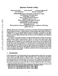
This means, the innovation guarantee property is satisfied and therefore, reliability and 100% throughput can be achieved (see Algorithm 2 (b) and corresponding Theorems 6 and 8 in Section IV-C). The intuition is that if all receivers have seen p, then their uncertainty can be resolved using only packets with index more than that of p because after decoding these packets, the receivers can compute q and hence obtain p as well. Therefore, even if the receivers have not decoded p, no information is lost by dropping it, provided it has been seen by all receivers. Next, we present an example that explains our algorithm for a simple two-receiver case. Section IV-C3 extends this scheme to more receivers. Example: Table I shows a sample of how the proposed idea works in a packet erasure broadcast channel with two receivers A and B. The sender’s queue is shown after the arrival point and before the transmission point of a slot (see Section III for details on the setup). In each slot, based on the ACKs, the sender identifies the next unseen packet for A and B. If they are the same packet, then that packet is sent. If not, their XOR is sent. It can be verified that with this rule, every reception causes each receiver to see its next unseen packet. In slot 1, p1 reaches A but not B. In slot 2, (p1 ⊕ p2 ) reaches A and B. Since A knows p1 , it can also decode p2 . As for B, it has now seen (but not decoded) p1 . At this point, since A and B have seen p1 , the sender drops it. This is fine even though B has not yet decoded p1 , because B will eventually decode p2 (in slot 4), at which time it can obtain p1 . Similarly, p2 , p3 and p4 will be dropped in slots 3, 5 and 6 respectively. However, the drop-when-decoded policy will drop p1 and p2 in slot 4, and p3 and p4 in slot 6. Thus, our new strategy clearly keeps the queue shorter. This is formally proved in Theorem 1 and Theorem 6. The example also shows that it is fine to drop packets before they are decoded. Eventually, the future packets will arrive, thereby allowing the decoding of all the packets. Related earlier work: In [20], Shrader and Ephremides study the queue stability and delay of block-based random linear coding versus uncoded ARQ for stochastic arrivals in a broadcast setting. However, this work does not consider the combination of coding and feedback in one scheme. In related work, [21] studies the case of load-dependent variable sized coding blocks with ACKs at the end of a block, using a bulk-service queue model. The main difference in our work is that receivers ACK packets even before decoding them, and this enables the sender to perform
online coding. Sagduyu and Ephremides [22] consider online feedback-based adaptation of the code, and propose a coding scheme for the case of two receivers. This work focuses on the maximum possible stable throughput, and does not consider the use feedback to minimize queue size or decoding delay. In [23], the authors study the throughput of a block-based coding scheme, where receivers acknowledge the successful decoding of an entire block, allowing the sender to move to the next block. Next, they consider the option of adapting the code based on feedback for the multiple receiver case. They build on the two-receiver case of [22] and propose a greedy deterministic coding scheme that may not be throughput optimal, but picks a linear combination such that the number of receivers that immediately decode a packet is maximized. In contrast, in our work we consider throughput-optimal policies that aim to minimize queue size and delay. In [24], Lacan and Lochin proposes an erasure coding algorithm called Tetrys to ensure reliability in spite of losses on the acknowledgment path. While this scheme also employs coding in the presence of feedback, their approach is to make minimal use of the feedback, in order to be robust to feedback losses. As opposed to such an approach, we investigate how best to use the available feedback to improve the coding scheme and other performance metrics. For instance, in the scheme in [24], packets are acknowledged (if at all) only when they are decoded, and these are then dropped from the coding window. However, we show in this work that by dropping packets when they are seen, we can maintain a smaller coding window without compromising on reliability and throughput. A smaller coding window translates to lower encoding complexity and smaller queue size at the sender in the case of stochastic arrivals. The use of ACKs and coded retransmissions in a packet erasure broadcast channel has been considered for multiple unicasts [25] and multicast ([26], [27], [28], [29]). The main goal of these works however, is to optimize the throughput. Other metrics such as queue management and decoding delay are not considered. In our work, we focus on using feedback to optimize these metrics as well, in addition to achieving 100% throughput in a multicast setting. Our coding module (in Section IV-C5) is closely related to the one proposed by Larsson in an independent work [28]. However, our algorithm is specified using the more general framework of seen packets, which allows us to derive the dropwhen-seen queue management algorithm and bring out the connection between the physical queue and virtual queue sizes. Reference [28] does not consider the queue
5
Time
Sender’s queue
Transmitted packet
Channel state
A Decoded
1 2 3 4 5 6
p1 p1 , p2 p2 , p3 p3 p3 , p4 p4
p1 p1 ⊕ p2 p2 ⊕ p3 p3 p3 ⊕ p4 p4
→ → 9 9 → →
A, A, A, A, A, A,
9 → → → 9 →
B B B B B B
p1 p1 , p2 p1 , p2 p1 , p2 p1 , p2 p1 , p2 , p3 , p4
B Seen but not decoded p3 -
Decoded
p1 , p2 , p3 p1 , p2 , p3 p1 , p2 , p3 , p4
Seen but not decoded p1 p1 , p2 -
TABLE I A N EXAMPLE OF THE DROP - WHEN - SEEN ALGORITHM
management problem. Moreover, using the notion of seen packets allows our algorithm to be compatible even with random coding. This in turn enables a simple ACK format and makes it suitable for practical implementation. (See Remark 2 for further discussion.) Implications of our new scheme: The newly proposed scheme has many useful implications: •
•
•
•
Queue size: The physical queue size is upperbounded by the sum of the backlogs in degrees of freedom between the sender and all the receivers. This fact implies that as the traffic load approaches capacity (as load factor ρ → 1), the expected � �size of 1 the physical queue at the sender is O 1−ρ . This is the same order as for single-receiver ARQ, and hence, is order-optimal. Queuing analysis: Our scheme forms a natural bridge between the virtual and physical queue sizes. It can be used to extend results on the stability of virtual queues such as [17], [18] and [30] to physical queues. Moreover, various results obtained for virtual queues from traditional queuing theory, such as the transform based analysis for the queue size of M/G/1 queues, or even a Jackson network type of result [8], can be extended to the physical queue size of nodes in a network coded system. Simple queue management: Our approach based on seen packets ensures that the sender does not have to store linear combinations of the packets in the queue to represent the basis of the coset space. Instead, it can store the basis using the original uncoded packets themselves. Therefore, the queue follows a simple first-in-first-out service discipline. Online encoding: All receivers see packets in the same order in which they arrived at the sender. This gives a guarantee that the information deficit at the receiver is restricted to a set of packets that advances in a streaming manner and has a stable size (namely, the set of unseen packets). In this sense, the proposed encoding scheme is truly online.
•
•
Easy decoding: Every transmitted linear combination is sparse – at most n packets are coded together for the n receiver case. This reduces the decoding complexity as well as the overhead for embedding the coding coefficients in the packet header. Extensions: We present our scheme for a single packet erasure broadcast channel. However, our algorithm is composable across links and can be applied to a tandem network of broadcast links. With suitable modifications, it can potentially be applied to a more general setup like the one in [7] provided we have feedback. Such extensions are discussed further in Section VII.
B. Decoding delay The drop-when-seen algorithm and the associated coding module do not guarantee that the seen packets will be decoded immediately. In general, there will be a delay in decoding, as the receiver will have to collect enough linear combinations involving the unknown packets before being able to decode the packets. Online feedback-based adaptation of the code with the goal of minimizing decoding delay has been studied in the context of a packet erasure broadcast channel in [31]. However, their notion of delay ignores the order in which packets are decoded. For the special case of only two receivers, [32] proposes a feedback-based coding algorithm that not only achieves 100% throughput, but also guarantees that every successful innovative reception will cause the receiver to decode a new packet. We call this property instantaneous decodability. However, this approach does not extend to the case of more than two receivers. With prior knowledge of the erasure pattern, [31] gives an offline algorithm that achieves optimal delay and throughput for the case of three receivers. However, in the online case, even with only three receivers, [32] shows through an example (Example V.1) that it is not possible to simultaneously guarantee instantaneous decodability as well as throughput optimality.
6
In the light of this example, our current work aims for a relaxed version of instantaneous decodability while still retaining the requirement of optimal throughput. We consider a situation with stochastic arrivals and study the problem using a queuing theory approach. Let λ and µ be the arrival rate and the channel quality parameter respectively. Let ρ , λ/µ be the load factor. We consider asymptotics when the load factor on the system tends to 1, while keeping either λ or µ fixed at a number less than 1. The optimal throughput requirement means that the queue of undelivered packets is stable for all values of ρ less than 1. Our new requirement on decoding delay is that the growth of the average 1 decoding delay as a function of 1−ρ as ρ → 1, should be of the same order as for the single receiver case. The expected per-packet delay of a receiver in a system with more than one receiver is clearly lower bounded by the corresponding quantity for a single-receiver system. Thus, instead of instantaneous decoding, we aim to guarantee asymptotically optimal decoding delay as the system load approaches capacity. The motivation is that in most practical systems, delay becomes a critical issue only when the system starts approaching its full capacity. When the load on the system is well within its capacity, the delay is usually small and hence not an issue. For the case of two receivers, it can be shown that this relaxed requirement is satisfied by the scheme in [32] due to the instantaneous decodability property, i.e., the scheme achieves the asymptotically optimal average decoding delay per packet for the two-receiver case. In our current work, we provide a new coding module for the case of three receivers that achieves optimal throughput. We conjecture that at the same time it also achieves an asymptotically optimal decoding delay as the system approaches capacity, in the following sense. With a single receiver, the optimal scheme is ARQ with no coding and we show that this achieves � � an expected per-packet delay at the sender of 1 Θ 1−ρ . For the three-receiver system, we conjecture �
�
1 , and that our scheme also achieves a delay of O 1−ρ thus meets the lower bound in an asymptotic sense. We also study a stronger notion of delay, namely the delivery delay, which measures delay till the point when the packet can be delivered to the application above, with the constraint that packets cannot be delivered out of order. We conjecture that our scheme is asymptotically optimal even in terms of delivery delay.
We have verified these conjectures through simulations for values of ρ that are very close to 1. It is useful to note that asymptotically optimal decoding delay translates to asymptotically optimal expected queue
occupancy at the sender using the simple queuing rule of dropping packets that have been decoded by all receivers. Adaptive coding allows the sender’s code to incorporate receivers’ states of knowledge and thereby enables the sender to control the evolution of the front of contiguous knowledge. Our schemes may thus be viewed as a step towards feedback-based control of the tradeoff between throughput and decoding delay, along the lines suggested in [33]. C. Organization The rest of the paper is organized as follows. Section III describes the packet erasure broadcast setting. Section IV is concerned with adaptive codes that minimize the sender’s queue size. In Section IV-A, we define and analyze a baseline algorithm that drops packets only when they have been decoded by all receivers. Section IV-B presents a generic form of our newly proposed algorithm, and introduces the idea of excluding from the sender’s queue, any knowledge that is common to all receivers. We show that the algorithm guarantees that the physical queue size tracks the virtual queue size. Section IV-C presents an easily implementable variant of the generic algorithm of Section IV-B, called the drop-whenseen algorithm. The drop-when-seen algorithm consists of a queuing module that provides guarantees on the queue size, and a coding module that provides guarantees on reliability and throughput, while complying with the queuing module. In Section VI, we investigate adaptive codes aimed at minimizing the receivers’ decoding delay. For the case of three receivers, we propose a new coding module that is proved to be throughput optimal and conjectured to be asymptotically optimal in terms of delay. Section VII presents some ideas on extending the algorithms to more general topologies and scenarios. Finally, Section VIII gives the conclusions. III. T HE
SETUP
In this paper, we consider a communication problem where a sender wants to broadcast a stream of data to n receivers. The data are organized into packets, which are essentially vectors of fixed size over a finite field Fq . A packet erasure broadcast channel connects the sender to the receivers. Time is slotted. The details of the queuing model and its dynamics are described next. The queuing model The sender is assumed to have an infinite buffer, i.e., a queue with no preset size constraints. We assume that the sender is restricted to use linear codes. Thus, every transmission is a linear combination of packets from the
7
incoming stream that are currently in the buffer. The vector of coefficients used in the linear combination summarizes the relation between the coded packet and the original stream. We assume that this coefficient vector is embedded in the packet header. A node can compute any linear combination whose coefficient vector is in the linear span of the coefficient vectors of previously received coded packets. In this context, the state of knowledge of a node can be defined as follows. Definition 3 (Knowledge of a node): The knowledge of a node at some point in time is the set of all linear combinations of the original packets that the node can compute, based on the information it has received up to that point. The coefficient vectors of these linear combinations form a vector space called the knowledge space of the node. We use the notion of a virtual queue to represent the backlog between the sender and receiver in terms of linear degrees of freedom. This notion was also used in [17], [18] and [30]. There is one virtual queue for each receiver. Definition 4 (Virtual queue): For j = 1, 2, . . . , n, the size of the j th virtual queue is defined to be the difference between the dimension of the knowledge space of the sender and that of the j th receiver. We will use the term physical queue to refer to the sender’s actual buffer, in order to distinguish it from the virtual queues. Note that the virtual queues do not correspond to real storage. Definition 5 (Degree of freedom): The term degree of freedom refers to one dimension in the knowledge space of a node. It corresponds to one packet worth of data. Definition 6 (Innovative packet): A coded packet with coefficient vector c is said to be innovative to a receiver with knowledge space V if c ∈ / V . Such a packet, if successfully received, will increase the dimension of the receiver’s knowledge space by one unit. Definition 7 (Innovation guarantee property): Let V denote the sender’s knowledge space, and Vj denote the knowledge space of receiver j for j = 1, 2, . . . , n. A coding scheme is said to have the innovation guarantee property if in every slot, the coefficient vector of the transmitted linear combination is in V \Vj for every j such that Vj 6= V . In other words, the transmission is innovative to every receiver except when the receiver already knows everything that the sender knows.
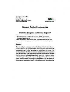
Arrivals Packets arrive into the sender’s physical queue according to a Bernoulli process4 of rate λ. An arrival at the physical queue translates to an arrival at each virtual queue since the new packet is a new degree of freedom that the sender knows, but none of the receivers knows. Service The channel accepts one packet per slot. Each receiver either receives this packet with no errors (with probability µ) or an erasure occurs (with probability (1 − µ)). Erasures occur independently across receivers and across slots. The receivers are assumed to be capable of detecting an erasure. We only consider coding schemes that satisfy the innovation guarantee property. This property implies that if the virtual queue of a receiver is not empty, then a successful reception reveals a previously unknown degree of freedom to the receiver and the virtual queue size decreases by one unit. We can thus map a successful reception by some receiver to one unit of service of the corresponding virtual queue. This means, in every slot, each virtual queue is served independently of the others with probability µ. The relation between the service of the virtual queues and the service of the physical queue depends on the queue update scheme used, and will be discussed separately under each update policy. Feedback We assume perfect delay-free feedback. In Algorithm 1 below, feedback is used to indicate successful decoding. For all the other algorithms, the feedback is needed in every slot to indicate the occurrence of an erasure. Timing Figure 1 shows the relative timing of various events within a slot. All arrivals are assumed to occur just after the beginning of the slot. The point of transmission is after the arrival point. For simplicity, we assume very small propagation time. Specifically, we assume that the transmission, unless erased by the channel, reaches the receivers before they send feedback for that slot and feedback from all receivers reaches the sender before the end of the same slot. Thus, the feedback incorporates the current slot’s reception also. Based on this feedback, packets are dropped from the physical queue just before 4
We have assumed Bernoulli arrivals for ease of exposition. However, we expect the results to hold for more general arrival processes as well.
8 Point where state variables are measured
Slot number t
λ µ + λµ λµ
λ + λµ
0
Point of arrival
Point of transmission
Point of feedback
Point of departure for physical queue
Fig. 1. Relative timing of arrival, service and departure points within a slot
the end of the slot, according to the queue update rule. Queue sizes are measured at the end of the slot. The load factor is denoted by ρ := λ/µ. In what follows, we will study the asymptotic behavior of the expected queue size and decoding delay under various policies, as ρ → 1 from below. For the asymptotics, we assume that either λ or µ is fixed, while the other varies causing ρ to increase to 1. IV. Q UEUE
SIZE
In this section, we first present a baseline algorithm – retain packets in the queue until the feedback confirms that they have been decoded by all the receivers. Then, we present a new queue update rule that is motivated by a novel coding algorithm. The new rule allows the physical queue size to track the virtual queue sizes. A. Algorithm 1: Drop when decoded (baseline) We first present the baseline scheme which we will call Algorithm 1. It combines a random coding strategy with a drop-when-decoded rule for queue update. The coding scheme is an online version of [8] with no preset generation size – a coded packet is formed by computing a random linear combination of all packets currently in the queue. With such a scheme, the innovation guarantee property will hold with high probability, provided the field size is large enough (We assume the field size is large enough to ignore the probability that the coded packet is not innovative. It can be incorporated into the model by assuming a slightly larger probability of erasure because a non-innovative packet is equivalent to an erasure.). For any receiver, the packets at the sender are unknowns, and each received linear combination is an equation in these unknowns. Decoding becomes possible whenever the number of linearly independent equations catches up with the number of unknowns involved. The difference between the number of unknowns and number of equations is essentially the backlog in degrees of freedom, i.e., the virtual queue size. Thus, a virtual
1 λµ
Time
λ µ + λµ λµ
λ µ + λµ λµ
2 λµ
3 λµ
Fig. 2. Markov chain representing the size of a virtual queue. Here ¯ := (1 − λ) and µ λ ¯ := (1 − µ).
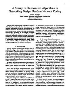
queue becoming empty translates to successful decoding at the corresponding receiver. Whenever a receiver is able to decode in this manner, it informs the sender. Based on this, the sender tracks which receivers have decoded each packet, and drops a packet if it has been decoded by all receivers. From a reliability perspective, this is fine because there is no need to involve decoded packets in the linear combination. Remark 1: In general, it may be possible to solve for some of the unknowns even before the virtual queue becomes empty. For example, this could happen if a newly received linear combination cancels everything except one unknown in a previously known linear combination. It could also happen if some packets were involved in a subset of equations that can be solved among themselves locally. Then, even if the overall system has more unknowns than equations, the packets involved in the local system can be decoded. However, these are secondary effects and we ignore them in this analysis. Equivalently, we assume that if a packet is decoded before the virtual queue becomes empty, the sender ignores the occurrence of this event and waits for the next emptying of the virtual queue before dropping the packet. We believe this assumption will not change the asymptotic behavior of the queue size, since decoding before the virtual queue becoming empty is a rare event with random linear coding over a large field. 1) The virtual queue size in steady state: We will now study the behavior of the virtual queues in steady state. But first, we introduce some notation: Q(t) := Size of the sender’s physical queue at the end of slot t Qj (t) := Size of the j th virtual queue at the end of slot t Figure 2 shows the Markov chain for Qj (t). If λ < µ, then the chain {Qj (t)} is positive recurrent and has a steady state distribution given by [34]: πk := lim P[Qj (t) = k] = (1 − α)αk , t→∞
k ≥ 0 (1)
λ(1−µ) where α = µ(1−λ) . Thus, the expected size of any virtual queue in steady
9
Using this fact, we can compute the expectation of Dj as follows:
state is given by: lim E[Qj (t)] =
t→∞
∞ X
jπj = (1 − µ) ·
j=0
ρ (1 − ρ)
(2)
Next, we analyze the physical queue size under this scheme. 2) The physical queue size in steady state: The following theorem characterizes the asymptotic behavior of the queue size under Algorithm 1, as the load on the system approaches capacity (ρ → 1). Theorem 1: The expected size of �the physical queue � 1 in steady state for Algorithm 1 is Ω (1−ρ)2 . Comparing with Equation (2), this result makes it clear that the physical queue size does not track the virtual queue size. (We assume that λ and µ are themselves away from 1, but only their ratio approaches 1 from below.) In the rest of this subsection, we present the arguments that lead to the above result. Let T be the time an arbitrary arrival in steady state spends in the physical queue before departure, excluding the slot in which the arrival occurs (Thus, if a packet departs immediately after it arrives, then T is 0.). A packet in the physical queue will depart when each virtual queue has become empty at least once since its arrival. Let Dj be the time starting from the new arrival, till the next emptying of the j th virtual queue. Then, T = maxj Dj and so, E[T ] ≥ E[Dj ]. Hence, we focus on E[Dj ]. We condition on the event that the state seen by the new arrival just before it joins the queue, is some state k. There are two possibilities for the queue state at the end of the slot in which the packet arrives. If the channel is ON in that slot, then there is a departure and the state at the end of the slot is k. If the channel is OFF, then there is no departure and the state is (k + 1). Now, Dj is simply the first passage time from the state at the end of that slot to state 0, i.e., the number of slots it takes for the system to reach state 0 for the first time, starting from the state at the end of the arrival slot. Let Γu,v denote the expected first passage time from state u to state v . The expected first passage time from state u to state 0, for u > 0 is derived in Appendix A, and is given by the following expression: Γu,0 =
u µ−λ
Now, because of the property that Bernoulli arrivals see time averages (BASTA) [35], an arbitrary arrival sees the same distribution for the size of the virtual queues, as the steady state distribution given in Equation (1).
E[Dj ] = =
∞ X
k=0 ∞ X
k=0 ∞ X
P(New arrival sees state k)E[Dj |State k] πk [µΓk,0 + (1 − µ)Γk+1,0 ]
µk + (1 − µ)(k + 1) µ−λ k=0 ρ 1−µ · = µ (1 − ρ)2 =
πk ·
(3)
Now, the expected time that an arbitrary arrival in steady state spends in the system is given by: 1 E[T ] = E[max Dj ] ≥ E[Dj ] = Ω j (1 − ρ)2 �
�
Since each virtual queue is positive recurrent (assuming λ < µ), the physical queue will also become empty infinitely often. Then we can use Little’s law to find the expected physical queue size. The expected queue size of the physical queue in steady state if we use algorithm 1 is given by: 1 lim E[Q(t)] = λE[T ] = Ω t→∞ (1 − ρ)2 �
�
This discussion thus completes the proof of Theorem 1 stated above. B. Algorithm 2 (a): Drop common knowledge In this section, we first present a generic algorithm that operates at the level of knowledge spaces and their bases, in order to ensure that the physical queue size tracks the virtual queue size. Later, we shall describe a simple-to-implement variant of this generic algorithm. 1) An intuitive description: The aim of this algorithm is to drop as much data as possible from the sender’s buffer while still satisfying the reliability requirement and the innovation guarantee property. In other words, the sender should store just enough data so that it can always compute a linear combination which is simultaneously innovative to all receivers who have an information deficit. As we shall see, the innovation guarantee property is sufficient for good performance. After each slot, every receiver informs the sender whether an erasure occurred, using perfect feedback. Thus, there is a slot-by-slot feedback requirement which means that the frequency of feedback messages is higher than in Algorithm 1. The main idea is to exclude from the queue, any knowledge that is known to all the receivers. More specifically, the queue’s contents must correspond to some basis of a vector space that is independent of the
10
intersection of the knowledge spaces of all the receivers. We show in Lemma 2 that with this queuing rule, it is always possible to compute a linear combination of the current contents of the queue that will guarantee innovation, as long as the field size is more than n, the number of receivers. The fact that the common knowledge is dropped suggests a modular or incremental approach to the sender’s operations. Although the knowledge spaces of the receivers keep growing with time, the sender only needs to operate with the projection of these spaces on dimensions currently in the queue, since the coding module does not care about the remaining part of the knowledge spaces that is common to all receivers. Thus, the algorithm can be implemented in an incremental manner. It will be shown that this incremental approach is equivalent to the cumulative approach. Table II shows the main correspondence between the notions used in the uncoded case and the coded case. We now present the queue update algorithm formally. Then we present theorems that prove that under this algorithm, the physical queue size at the sender tracks the virtual queue size. All operations in the algorithm occur over a finite field of size q > n. The basis of a node’s knowledge space is stored as the rows of a basis matrix. The representation and all operations are in terms of local coefficient vectors (i.e., with respect to the current contents of the queue) and not global ones (i.e., with respect to the original packets). 2) Formal description of the algorithm: Algorithm 2 (a) 1. Initialize basis matrices B , B1 , . . . , Bn to the empty matrix. These contain the bases of the incremental knowledge spaces of the sender and receivers in that order. 2. Initialize the vector g to the zero vector. This will hold the coefficients of the transmitted packet in each slot. In every time slot, do: 3. Incorporate new arrivals: Let a be the number of new packets that arrived at the beginning of the slot. Place these packets at the end of the queue. Let B have b rows. Set B to Ia+b . (Im denotes the identity matrix of size m.) Note that B will always be an identity matrix. To make the number of columns of all matrices consistent (i.e., equal to a + b), append a all-zero columns to each Bj . 4. Transmission: If B is not empty, update g to be any vector that is in span(B), but not in ∪{j:Bj (B} span(Bj ). (Note:
span(B) denotes the row space of B .) Lemma 2 shows that such a g exists. Let y1 , y2 , . . . yQ represent the current contents of the queue, where the queue size Q = (a+b). Compute P the linear combination Q i=1 gi yi and transmit it on the packet erasure broadcast channel. If B is empty, set g to 0 and transmit nothing. 5. Incorporate feedback: Once the feedback arrives, for every receiver j = 1 to n, do: If g 6= 0 and the transmission was successfully received by receiver j in this slot, append g as a new row to Bj . 6. Separate out the knowledge that is common to all receivers: Compute the following (the set notation used here considers the matrices as a set of row vectors): B∆ := Any basis of ∩nj=1 span(Bj ). B′ := Completion of B∆ into a basis of span(B). B ′′ := B ′ \B∆ . Bj′ := Completion of B∆ into a basis of span(Bj ) in such a way that, if we define Bj′′ := Bj′ \B∆ , then the following holds: Bj′′ ⊆ span(B ′′ ). Lemma 1 proves that this is possible. 7. Update the queue contents: Replace the contents of the queue with packets ′ of the form PQ h y for each h ∈ y1′ , y2′ , . . . yQ ′ i=1 i i ′′ B . The new queue size Q′ is thus equal to the number of rows in B ′′ . 8. Recompute local coefficient vectors with respect to the new queue contents: Find a matrix Cj such that Bj′′ = Xj B ′′ (this is possible because Bj′′ ⊆ span(B ′′ )). Call Xj the new Bj . Update the value of B to IQ′ . 9. Go back to step 3 for the next slot. The above algorithm essentially removes, at the end of each slot, the common knowledge (represented by the basis B∆ ) and retains only the remainder B ′′ . The knowledge spaces of the receivers are also represented in an incremental manner in the form of Bj′′ , excluding the common knowledge. Since Bj′′ ⊆ span(B ′′ ), the Bj′′ vectors can be completely described in terms of the vectors in B ′′ . It is as if B∆ has been completely removed from the entire setting, and the only goal remaining is to convey span(B ′′ ) to the receivers. Hence, it is sufficient to store linear combinations corresponding to B ′′ in the queue. B ′′ and Bj′′ get mapped to the new B and Bj , and the process repeats in the next slot. Lemma 1: In step 5 of the algorithm above, it is possible to complete B∆ into a basis Bj′ of each span(Bj )
11
Knowledge represented by Amount of knowledge
Uncoded Networks Set of received packets Number of packets received
Queue stores
All undelivered packets
Update rule after each transmission
If a packet has been received by all receivers drop it.
Coded Networks Vector space spanned by the coefficient vectors of the received linear combinations Number of linearly independent (innovative) linear combinations of packets received (i.e., dimension of the knowledge space) Linear combination of packets which form a basis for the coset space of the common knowledge at all receivers Recompute the common knowledge space V∆ ; Store a new set of linear combinations so that their span is independent of V∆
TABLE II T HE
UNCODED VS . CODED CASE
such that Bj′′ ⊆ span(B ′′ ). Proof: We show that any completion of B∆ into a basis of span(Bj ) can be changed to a basis with the required property. Let B∆ = {b1 , b2 , . . . , bm }. Suppose we complete this into a basis Cj of span(Bj ) such that: Cj = B∆ ∪ {c1 , c2 , . . . , c|Bj |−m }
Now, we claim that at the beginning of step 6, span(Bj ) ⊆ span(B) for all j . This can be proved by induction on the slot number, using the way the algorithm updates B and the Bj ’s. Intuitively, it says that any receiver knows a subset of what the sender knows. Therefore, for each vector c ∈ Cj \B∆ , c must also be in span(B). Now, since B∆ ∪ B ′′ is a basis of span(B), P ′ ′ ′′ we can write c as m i=1 αi bi +c with c ∈ span(B ). In ′ this manner, each ci gives a distinct ci . It is easily seen that Cj′ := B∆ ∪ {c′1 , c′2 , . . . , c′|Bj |−m } is also a basis of the same space that is spanned by Cj . Moreover, it satisfies the property that Cj′ \B∆ ⊆ span(B ′′ ). Lemma 2: ([30]) Let V be a vector space with dimension k over a field of size q , and let V1 , V2 , . . . Vn , be subspaces of V , of dimensions k1 , k2 , . . . , kn respectively. Suppose that k > ki for all i = 1, 2, . . . , n. Then, there exists a vector that is in V but is not in any of the Vi ’s, if q > n. Proof: See [30] for the proof. This lemma is also closely related to the result in [28], which derives the smallest field size needed to ensure innovation guarantee. 3) Connecting the physical and virtual queue sizes: In this subsection, we will prove the following result that relates the size of the physical queue at the sender and the virtual queues, which themselves correspond to the backlog in degrees of freedom. Theorem 2: For Algorithm 2 (a), the physical queue size at the sender is upper bounded by the sum of the
backlog differences between the sender and each receiver in terms of the number of degrees of freedom. Let a(t) denote the number of arrivals in slot t, and let A(t) be the total number of arrivals up to and including P slot t, i.e., A(t) = tt′ =0 a(t′ ). Let B(t) (resp. Bj (t)) be the matrix B (resp. Bj ) after incorporating the slot t arrivals, i.e., at the end of step 3 in slot t. Let H(t) be a matrix whose rows are the global coefficient vectors of the queue contents at the end of step 3 in time slot t, i.e., the coefficient vectors in terms of the original packet A(t) stream. Note that each row of H(t) is in Fq . Let g(t) denote the vector g at the calculated in step 4 in time slot t, i.e., the local coefficient vector of the packet transmitted in slot t. Also, let B∆ (t) (resp. B ′′ (t), Bj′ (t) and Bj′′ (t)) denote the matrix B∆ (resp. B ′′ , Bj′ and Bj′′ ) at the end of step 6 in time slot t. Lemma 3: The rows of H(t) are linearly independent for all t. Proof: The proof is by induction on t. Basis step: In the beginning of time slot 1, a(1) packets arrive. So, H(1) = Ia(1) and hence the rows are linearly independent. Induction hypothesis: Assume H(t − 1) has linearly independent rows. Induction step: The queue is updated such that the linear combinations corresponding to local coefficient vectors in B ′′ are stored, and subsequently, the a(t) new arrivals are appended. Thus, the relation between H(t − 1) and H(t) is: H(t) =
"
B ′′ (t − 1)H(t − 1) 0 0 Ia(t)
#
Now, B ′′ (t − 1) has linearly independent rows, since the rows form a basis. The rows of H(t − 1) are also linearly independent by hypothesis. Hence, the rows of B ′′ (t − 1)H(t − 1) will also be linearly independent. Appending a(t) zeros and then adding an identity matrix
12 STEP 6 Separate out common knowledge
STEP 5 Incorporate channel state feedback STEP 3 Incorporate arrivals of slot t U (t ), V (t )
′ (t) ⊕ U ′′ (t) U (t) = U∆
Uj′ (t) Uj′′ (t)
U ' j (t ), V ' j (t ) U ' ∆ (t ), V ' ∆ (t ) U ' ' (t ), U ' ' j (t )
U j (t ), V j (t ) Slot (t-1)
domain: =
′ U∆ (t) ′′
⊕
Uj′′ (t)
⊆ U (t),
(5) and,
∀j = 1, 2, . . . , n
Slot t
From the above properties, we can infer that U1′′ (t) + + . . . Un′′ (t) ⊆ U ′′ (t). After incorporating the arrivals in slot t + 1, this gives U1 (t + 1) + U2 (t + 1) + . . . Un (t + 1) ⊆ U (t + 1). Since this is true for all t, we write it as: U1 (t) + U2 (t) + . . . Un (t) ⊆ U (t)
block in the right bottom corner does not affect the linear independence. Hence, H(t) also has linearly independent rows. Define the following: := := := := := :=
Row span of Row span of Row span of ∩nj=1 Uj′ (t) Row span of Row span of
H(t) Bj (t)H(t) Bj′ (t)H(t) B ′′ (t)H(t) Bj′′ (t)H(t)
All the vector spaces defined above are subspaces of A(t) Fq . Figure 3 shows the points at which these subspaces are defined in the slot. The fact that H(t) has full row rank (proved above in Lemma 3) implies that the operations performed by the algorithm in the domain of the local coefficient vectors can be mapped to the corresponding operations in the domain of the global coefficient vectors: ′ (t) is indeed the row 1) The intersection subspace U∆ span of B∆ (t)H(t). 2) Let Rj (t) be an indicator (0-1) random variable which takes the value 1 iff the transmission in slot t is successfully received without erasure by receiver j and in addition, receiver j does not have all the information that the sender has. Let g˜j (t) := Rj (t)g(t)H(t). Then,
Uj′ (t) = Uj (t) ⊕ span(g˜j (t))
(7)
U2′′ (t)
Fig. 3. The main steps of the algorithm, along with the times at which the various U (t)’s are defined
U (t) Uj (t) Uj′ (t) ′ (t) U∆ U ′′ (t) Uj′′ (t)
(6)
(4)
where ⊕ denotes direct sum of vector spaces. The way the algorithm chooses g(t) guarantees that if Rj (t) is non-zero, then g˜j (t) will be outside the corresponding Uj (t), i.e., it will be innovative. This fact is emphasized by the direct sum in this equation. 3) Because of the way the algorithm performs the completion of the bases in the local domain in step 6, the following properties hold in the global
(8)
Now, in order to relate the queue size to the backlog in number of degrees of freedom, we define the following vector spaces which represent the cumulative knowledge of the sender and receivers (See Figure 3 for the timing): V (t)
:=
Vj (t)
:=
Vj′ (t)
:=
V∆ (t) V∆′ (t)
:= :=
Sender’s knowledge space after incorporating the arrivals (at the end of step 3) A(t) in slot t. This is simply equal to Fq Receiver j ’s knowledge space at the end of step 3 in slot t Receiver j ’s knowledge space in slot t, after incorporating the channel state feedback into Vj (t), i.e., Vj′ (t) = Vj (t)⊕ span(g˜j (t)). ∩nj=1 Vj (t) ∩nj=1 Vj′ (t)
For completeness, we now prove the following facts about direct sums of vector spaces that we will use. Lemma 4: Let V be a vector space and let V∆ , U1 , U2 , . . . Un be subspaces of V such that, V∆ is independent of the span of all the Uj ’s, i.e., dim[V∆ ∩ (U1 + U2 + . . . + Un )] = 0. Then, V∆ ⊕ [∩ni=1 Ui ] = ∩ni=1 [V∆ ⊕ Ui ]
See Appendix B for the proof. Lemma 5: Let A, B, and C be three vector spaces such that B is independent of C and A is independent of B ⊕ C . Then the following hold: 1) A is independent of B . 2) A ⊕ B is independent of C . 3) A ⊕ (B ⊕ C) = (A ⊕ B) ⊕ C . See Appendix C for the proof. Theorem 3: For all t ≥ 0, V (t) = V∆ (t) ⊕ U (t) Vj (t) = V∆ (t) ⊕ Uj (t) V∆′ (t)
= V∆ (t) ⊕
′ U∆ (t)
∀j = 1, 2, . . . n
13
Proof: The proof is by induction on t. Basis step: At t = 0, V (0), U (0) as well as all the Vj (0)’s and Uj (0)’s are initialized to {0}. Consequently, V∆ (0) is also {0}. It is easily seen that these initial values satisfy the equations in the theorem statement.
V (t) = V∆ (t) ⊕ U (t)
(9)
Vj (t) = V∆ (t) ⊕ Uj (t), ∀j = 1, 2, . . . n ′ V∆′ (t) = V∆ (t) ⊕ U∆ (t)
(10) (11)
Induction Step: We now prove that they hold in slot (t + 1). We have: V (t) = = =
(from (9))
′ V∆ (t) ⊕ [U∆ (t) ⊕ U ′′ (t)] ′ [V∆ (t) ⊕ U∆ (t)] ⊕ U ′′ (t) V∆′ (t) ⊕ U ′′ (t)
(from (5)) (Lemma 5) (from (11))
Thus, we have proved: V (t) = V∆′ (t) ⊕ U ′′ (t)
(12)
Now, we incorporate the arrivals in slot (t + 1). This converts V∆′ (t) to V∆ (t+1), U ′′ (t) to U (t+1), and V (t) to V (t + 1), due to the following operations: Basis of V∆ (t + 1) = Basis of U (t + 1) Basis of V (t + 1)
h
=
"
=
"
Basis of V∆′ (t) 0
Vj (t + 1) = V∆ (t + 1) ⊕ Uj (t + 1),
∀j = 1, 2, . . . n
And finally, V∆′ (t + 1)
Induction Hypothesis: We assume the equations hold at t, i.e.,
= V∆ (t) ⊕ U (t)
Vj′ (t), V∆′ (t), and Uj′′ (t), thereby converting them into bases of Vj (t + 1), V∆ (t + 1), and Uj (t + 1) respectively. These changes do not affect the above relation, and we get:
i
Basis of U ′′ (t) 0 0 Ia(t+1) Basis of V (t) 0 0 Ia(t+1)
# #
Incorporating these modifications into (12), we get: V (t + 1) = V∆ (t + 1) ⊕ U (t + 1)
Now, consider each receiver j = 1, 2, . . . n. Vj′ (t)
=
∩nj=1 Vj′ (t + 1)
=
∩nj=1 [Vj (t + 1) ⊕ span(g˜j (t + 1))]
=
∩nj=1 [V∆ (t + 1) ⊕ Uj (t + 1) ⊕ span(g˜j (t + 1))]
(a)
=
V∆ (t + 1) ⊕ ∩nj=1 [Uj (t + 1) ⊕ span(g˜j (t + 1))]
=
′ V∆ (t + 1) ⊕ U∆ (t + 1)
Step (a) is justified as follows. Using equation (8) and the fact that g˜j (t+1) was chosen to be inside U (t+1), we can show that the span of all the [Uj (t+1)⊕span(g˜j (t+ 1))]’s is inside U (t + 1). Now, from the induction step above, V∆ (t + 1) is independent of U (t + 1). Therefore, V∆ (t + 1) is independent of the span of all the [Uj (t + 1) ⊕ span(g˜j (t + 1))]’s. We can therefore apply Lemma 4. Theorem 4: Let Q(t) denote the size of the queue after the arrivals in slot t have been appended to the queue. Q(t) = dim V (t) − dim V∆ (t)
Proof: Q(t) = dim U (t) = dim U ′′ (t − 1) + a(t) ′ = dim U (t − 1) − dim U∆ (t − 1) + a(t)
(using (5) ′ = dim V (t − 1) − dim V∆ (t − 1) − dim U∆ (t) + a(t)
(from Theorem 3) = dim V (t − 1) − dim V∆′ (t) + a(t)
(from Theorem 3) = dim V (t) − dim V∆ (t)
= Vj (t) ⊕ span(g˜j (t)) = [V∆ (t) ⊕ Uj (t)] ⊕ span(g˜j (t))
(from (10))
= V∆ (t) ⊕ [Uj (t) ⊕ span(g˜j (t))]
(Lemma 5)
= = = =
V∆ (t) ⊕ Uj′ (t) ′ V∆ (t) ⊕ [U∆ (t) ⊕ Uj′′ (t)] ′ [V∆ (t) ⊕ U∆ (t)] ⊕ Uj′′ (t) V∆′ (t) ⊕ Uj′′ (t)
Lemma 6: Let V1 , V2 , . . . , Vk be subspaces of a vector space V . Then, for k ≥ 1,
(from (4)) (from (6)) (Lemma 5) (from (11))
Incorporating the new arrivals into the subspaces involves adding a(t + 1) all-zero columns to the bases of
dim(V1 ∩ V2 ∩ . . . ∩ Vk ) ≥
k X
dim(Vi ) − (k − 1)dim(V )
i=1
Proof: For any two subspaces X and Y of V , dim(X ∩ Y ) + dim(X + Y ) = dim(X) + dim(Y )
where X + Y denotes the span of subspaces X and Y .
14
linear combinations of packets in the queue like in Algorithm 2 (a). Instead only original packets need to be dim(X ∩ Y ) = dim(X) + dim(Y ) − dim(X + Y ) stored, and the queue can be operated in a simple first≥ dim(X) + dim(Y ) − dim(V ) (13)in-first-out manner. We now present some mathematical (since X + Y is also a subspace of V ) preliminaries before describing the algorithm. 1) Some preliminaries: The newly proposed algoNow, we prove the lemma by induction on k. rithm uses the notion of reduced row echelon form Basis step: (RREF) of a matrix to represent the knowledge of a k = 1 : LHS = dim(V1 ), RHS = dim(V1 ) receiver. Hence, we first recapitulate the definition and k = 2 : LHS = dim(V1 ∩ V2 ), RHS = dim(V1 ) + some properties of the RREF from [19], and present the dim(V2 ) − dim(V ) connection between the RREF and the notion of seeing The claim follows from inequality (13). packets. Induction Hypothesis: Definition 8 (Reduced row echelon form (RREF)): A For some arbitrary k, matrix is said to be in reduced row echelon form if it k−1 satisfies the following conditions: X k−1 dim(∩i=1 Vi ) ≥ dim(Vi ) − (k − 2)dim(V ) 1) The first nonzero entry of every row is 1. i=1 2) The first nonzero entry of any row is to the right Induction Step: of the first nonzero entry of the previous row. k−1 Vi ) dim(∩ki=1 Vi ) = dim(Vk ∩ ∩i=1 3) The entries above the first nonzero row of any row k−1 are all zero. ≥ dim(Vk ) + dim(∩i=1 Vi ) − dim(V ) (using (13)) # "k−1 The RREF leads to a standard way to represent a vecX tor space. Given a vector space, consider the following dim(Vi ) − (k − 2)dim(V ) ≥ dim(Vk ) + operation – arrange the basis vectors in any basis of i=1 −dim(V ) the space as the rows of a matrix, and perform Gaussian k elimination. This process essentially involves a sequence X = dim(Vi ) − (k − 1)dim(V ) of elementary row transformations and it produces a i=1 unique matrix in RREF such that its row space is the The above result can be rewritten as: given vector space. We call this the RREF basis matrix k of the space. We will use this representation for the X dim(V )−dim(V1 ∩V2 ∩. . . Vk ) ≤ [dim(V )−dim(Vi )] knowledge space of the receivers. i=1 Let V be the knowledge space of some receiver. Sup(14) pose m packets have arrived at the sender so far. Then the receiver’s knowledge consists of linear combinations of Using this result, we can now prove Theorem 2. some collection of these m packets, i.e., V is a subspace Proof of Theorem 2: If we apply Lemma 6 to the of Fm q . Using the procedure outlined above, we can vector spaces Vj (t), j = 1, 2, . . . , n and V (t), then the compute the dim(V ) × m RREF basis matrix of V over left hand side of inequality (14) becomes the sender Fq . queue size (using Theorem 4), while the right hand side In the RREF basis, the first nonzero entry of any row becomes the sum of the differences in backlog between is called a pivot. Any column with a pivot is called the sender and the receivers, in terms of the number of a pivot column. By definition, each pivot occurs in a degrees of freedom. Thus, we have proved Theorem 2. different column. Hence, the number of pivot columns equals the number of nonzero rows, which is dim[V ]. Let pk denote the packet with index k. The columns C. Algorithm 2 (b): Drop when seen are ordered so that column k maps to packet pk . The The drop-when-seen algorithm can be viewed as a following theorem connects the notion of seeing packets specialized variant of the generic Algorithm 2 (a) given to the RREF basis. above. It uses the notion of seen packets (defined in SecTheorem 5: A node has seen a packet with index k if tion II) to represent the bases of the knowledge spaces. and only if the kth column of the RREF basis B of the This leads to a simple and easy-to-implement version knowledge space V of the node is a pivot column. Proof: The ‘if’ part is clear. If column k of B of the algorithm which, besides ensuring that physical queue size tracks virtual queue size, also provides some is a pivot column, then the corresponding pivot row practical benefits. For instance, the sender need not store corresponds to a linear combination known to the node, Hence,
15
of the form pk + q, where q involves only packets with index more than k. Thus, the node has seen pk . For the ‘only if’ part, suppose column k of B does not contain a pivot. Then, in any linear combination of the rows, rows with pivot after column k cannot contribute anything to column k. Rows with pivot before column k will result in a non-zero term in some column to the left of k. Since every vector in V is a linear combination of the rows of B , the first non-zero term of any vector in V cannot be in column k. Thus, pk could not have been seen. Since the number of pivot columns is equal to the dimension of the vector space, we obtain the following corollary. Corollary 1: The number of packets seen by a receiver is equal to the dimension of its knowledge space. The next corollary introduces a useful concept. Corollary 2: If receiver j has seen packet pk , then it knows exactly one linear combination of the form pk +q such that q involves only unseen packets with index more than k. Proof: We use the same notation as above. The receiver has seen pk . Hence, column k in B is a pivot column. By definition of RREF, in the row containing the pivot in column k, the pivot value is 1 and subsequent nonzero terms occur only in non-pivot columns. Thus, the corresponding linear combination has the given form pk +q, where q involves only unseen packets with index more than k. We now prove uniqueness by contradiction. Suppose the receiver knows another such linear combination pk + q′ where q′ also involves only unseen packets. Then, the receiver must also know (q − q′ ). But this means the receiver has seen some packet involved in either q or q′ – a contradiction. Definition 9 (Witness): We denote the unique linear combination guaranteed by Corollary 2 as Wj (pk ), the witness for receiver j seeing pk . 2) Description of Algorithm 2 (b): The central idea of the algorithm is to keep track of seen packets instead of decoded packets. The two main parts of the algorithm are the coding and queue update modules. In Section IV-C5, we present the formal description of our coding module. The coding module computes a linear combination g that will cause any receiver that receives it, to see its next unseen packet. First, for each receiver, the sender computes its knowledge space using the feedback and picks out its next unseen packet. Only these packets will be involved in g, and hence we call them the transmit set. Now, we need to select coefficients for each packet in this set. Clearly, the receiver(s) waiting to see the oldest packet in the transmit set (say p1 ) will
be able to see it as long as its coefficient is not zero. Consider a receiver that is waiting to see the second oldest packet in the transmit set (say p2 ). Since the receiver has already seen p1 , it can subtract the witness for p1 , thereby canceling it from g. The coefficient of p2 must be picked such that after subtracting the witness for p1 , the remaining coefficient of p2 in g is nonzero. The same idea extends to the other coefficients. The receiver can cancel packets involved in g that it has already seen by subtracting suitable multiples of the corresponding witnesses. Therefore, the coefficients for g should be picked such that for each receiver, after canceling the seen packets, the remaining coefficient of the next unseen packet is non-zero. Then, the receiver will be able to see its next unseen packet. Theorem 8 proves that this is possible if the field size is at least n, the number of receivers. With two receivers, the coding module is a simple XOR based scheme (see Table I). Our coding scheme meets the innovation guarantee requirement because Theorem 5 implies that a linear combination that would cause a new packet to be seen brings in a previously unknown degree of freedom. The fact that the coding module uses only the next unseen packet of all receivers readily implies the following queue update rule. Drop a packet if all receivers have seen it. This simple rule ensures that the physical queue size tracks the virtual queue size. Remark 2: In independent work, [28] proposes a coding algorithm which uses the idea of selecting those packets for coding, whose indices are one more than each receiver’s rank. This corresponds to choosing the next unseen packets in the special case where packets are seen in order. Moreover, this algorithm picks coding coefficients in a deterministic manner, just like our coding module. Therefore, our module is closely related to the algorithm of [28]. However, our algorithm is based on the framework of seen packets. This allows several benefits. First, it immediately leads to the drop-when-seen queue management algorithm, as described above. In contrast, [28] does not consider queuing aspects of the problem. Second, in this form, our algorithm readily generalizes to the case where the coding coefficients are picked randomly. The issue with random coding is that packets may be seen out of order. Our algorithm will guarantee innovation even in this case (provided the field is large), by selecting a random linear combination of the next unseen packets of the receivers. However, the algorithm of [28] may not work well here, as it may pick packets that have already been seen, which could cause non-innovative transmissions. The compatibility of our algorithm with random cod-
16
ing makes it particularly useful from an implementation perspective. With random coding, each receiver only needs to inform the sender the set of packets it has seen. There is no need to convey the exact knowledge space. This can be done simply by generating a TCP-like cumulative ACK upon seeing a packet. Thus, the ACK format is the same as in traditional ARQ-based schemes. Only its interpretation is different. We next present the formal description and analysis of the queue update algorithm. 3) The queuing module: The algorithm works with the RREF bases of the receivers’ knowledge spaces. The coefficient vectors are with respect to the current queue contents and not the original packet stream. Algorithm 2 (b) 1. Initialize matrices B1 , B2 , . . . , Bn to the empty matrix. These matrices will hold the bases of the incremental knowledge spaces of the receivers. 2. Incorporate new arrivals: Suppose there are a new arrivals. Add the new packets to the end of the queue. Append a all-zero columns on the right to each Bj for the new packets. 3. Transmission: If the queue is empty, do nothing; else compute g using the coding module and transmit it. 4. Incorporate channel state feedback: For every receiver j = 1 to n, do: If receiver j received the transmission, include the coefficient vector of g in terms of the current queue contents, as a new row in Bj . Perform Gaussian elimination. 5. Separate out packets that all receivers have seen: Update the following sets and bases: Sj′ := Set of packets corresponding to the pivot columns of Bj ′ := ∩n S ′ S∆ j=1 j New Bj := Sub-matrix of current Bj obtained by ′ and corresponding pivot excluding columns in S∆ rows. ′ . 6. Update the queue: Drop the packets in S∆ 7. Go back to step 2 for the next slot. 4) Connecting the physical and virtual queue sizes: The following theorem describes the asymptotic growth of the expected physical queue size under our new queuing rule. Theorem 6: For Algorithm 2 (b), the physical queue size at the sender is upper-bounded by the sum of the virtual queue sizes, i.e., the sum of the degrees-offreedom backlog between the sender and the receivers. Hence, the expected size of the physical queue in steady
state for Algorithm 2 (b) is O
�
1 1−ρ
�
.
In the rest of this section, we will prove the above result. Now, in order to relate the queue size to the backlog in number of degrees of freedom, we will need the following notation: S(t) := Set of packets arrived at sender till the end of slot t V (t) := Sender’s knowledge space after incorporating |S(t)| the arrivals in slot t. This is simply equal to Fq Vj (t) := Receiver j ’s knowledge space at the end of slot t. It is a subspace of V (t). Sj (t) := Set of packets receiver j has seen till end of slot t We will now formally argue that Algorithm 2 (b) indeed implements the drop-when-seen rule in spite of the incremental implementation. In any slot, the columns of Bj are updated as follows. When new packets are appended to the queue, new columns are added to Bj on the right. When packets are dropped from the queue, corresponding columns are dropped from Bj . There is no rearrangement of columns at any point. This implies that a one-to-one correspondence is always maintained between the columns of Bj and the packets currently in the queue. Let Uj (t) be the row space of Bj at time t. Thus, if (u1 , u2 , . . . , uQ(t) ) is any vector in Uj (t), it corresponds to a linear combination of the form PQ(t) th packet in the queue at i=1 ui pi , where pi is the i time t. The following theorem connects the incremental knowledge space Uj (t) to the cumulative knowledge space Vj (t). Theorem 7: In Algorithm 2 (b), for each receiver j , at the end of slot t, for any u ∈ Uj (t), the linear PQ(t) combination i=1 ui pi is known to the receiver j , where pi denotes the ith packet in the queue at time t. Proof: We will use induction on t. For t = 0, the system is completely empty and the statement is vacuously true. Let us now assume that the statement is true at time (t − 1). Consider the operations in slot t. A new row is added to Bj only if the corresponding linear combination has been successfully received by receiver j . Hence, the statement is still true. Row operations involved in Gaussian elimination do not alter the row space. Finally, when some of the pivot columns are dropped along with the corresponding pivot rows in step 5, this does not affect the linear combinations to which the remaining rows correspond because the pivot columns have a 0 in all rows except the pivot row. Hence, the three operations that are performed between slot (t − 1) and slot t do not affect the property that
17
= = = ≤ =
Pn
�
�
dim[V (t)] − dim[Vj (t)] , which is the sum of the virtual queue sizes. Finally, we can find the asymptotic behavior of the physical queue size in steady state under Algorithm 2 (b). Since� the �expected virtual queue sizes themselves 1 are all O 1−ρ from Equation (2), we obtain the stated result. 5) The coding module: We now present a coding module that is compatible with the drop-when-seen queuing algorithm in the sense that it always forms a linear combination using packets that are currently in the queue maintained by the queuing module. In addition, we show that the coding module satisfies the innovation guarantee property. Let {u1 , u2 , . . . , um } be the set of indices of the next unseen packets of the receivers, sorted in ascending order (In general, m ≤ n, since the next unseen packet may be the same for some receivers). Exclude receivers whose next unseen packets have not yet arrived at the sender. Let R(ui ) be the set of receivers whose next unseen packet is pui . We now present the coding module to select the linear combination for transmission. 1) Loop over next unseen packets For j = 1 to m, do: All receivers in R(uj ) have seen packets pui k X k for i < j . Now, ∀r ∈ R(uj ), find yr := |A| − | ∩i=1 Ai | ≤ (|A| − |Ai |) (15) Pj−1 i=1 i=1 αi Wr (pui ), where Wr (pui ) is the witness for receiver r seeing pui . Pick αj ∈ Fq such that Proof: αj is different from the coefficient of puj in yr |A| − | ∩ki=1 Ai | for each r ∈ R(uj ). P |A ∩ (∩ki=1 Ai )c | (since the Ai ’s are subsets of A) 2) Compute the transmit packet: g := m i=1 αi pui k c It is easily seen that this coding module is compatible |A ∩ (∪i=1 Ai )| (by De Morgan’s law) with the drop-when-seen algorithm. Indeed, it does not k c | ∪i=1 (A ∩ Ai )| (distributivity) use any packet that has been seen by all receivers in k X c the linear combination. It only uses packets that at least |A ∩ Ai | (union bound) one receiver has not yet seen. The queue update module i=1 k retains precisely such packets in the queue. The next X (|A| − |Ai |) theorem presents a useful property of the coding module.
the vectors in the row space of Bj correspond to linear combinations that are known at receiver j . This proves the theorem. If a packet corresponds to a pivot column in Bj , the corresponding pivot row is a linear combination of the packet in question with packets that arrived after it. From the above theorem, receiver j knows this linear combination which means it has seen the packet. This leads to the following corollary. Corollary 3: If a packet corresponds to a pivot column in Bj , then it has been seen by receiver j . ′ (t) consists of those packets in Thus, in step 5, S∆ the queue that all receivers have seen by the end of slot t. In other words, the algorithm retains only those packets that have not yet been seen by all receivers. Even though the algorithm works with an incremental version of the knowledge spaces, namely Uj (t), it maintains the queue in the same way as if it was working with the cumulative version Vj (t). Thus, the incremental approach is equivalent to the cumulative approach. We will require the following lemma to prove the main theorem. Lemma 7: Let A1 , A2 , . . . , Ak be subsets of a set A. Then, for k ≥ 1,
j=1
i=1
Now, we are ready to prove Theorem 6. Proof of Theorem 6: Since the only packets in the queue at any point are those that not all receivers have seen, we obtain the following expression for the physical queue size at the sender at the end of slot t: Q(t) = |S(t)| − | ∩nj=1 Sj (t)|
If we apply Lemma 7 to the sets S(t) and Sj (t), j = 1, 2, . . . , n then the left hand side of inequality (15) becomes the sender queue size Q(t) given above. Now, |Sj (t)| = dim[Vj (t)], using Corollary 1. Hence the right hand side of inequality (15) can be rewritten as
Theorem 8: If the field size is at least n, then the coding module picks a linear combination that will cause any receiver to see its next unseen packet upon successful reception. Proof: First we show that a suitable choice always exists for αj that satisfies the requirement in step 1. For r ∈ R(u1 ), yr = 0. Hence, as long as α1 6= 0, the condition is satisfied. So, pick α1 = 1. Since at least one receiver is in R(u1 ), we have that for j > 1, |R(uj )| ≤ (n − 1). Even if each yr for r ∈ R(uj ) has a different coefficient for puj , that covers only (n−1) different field elements. If q ≥ n, then there is a choice left in Fq for αj .
18
Now, we have to show that the condition given in step 1 implies that the receivers will be able to see their next unseen packet. Indeed, for all j from 1 to m, and for all r ∈ R(uj ), receiver r knows yr , since it is a linear combination of witnesses of r . Hence, if r successfully receives g, it can compute (g − yr ). Now, g and yr have the same coefficient for all packets with index less than uj , and a different coefficient for puj . Hence, (g − yr ) will involve puj and only packets with index beyond uj . This means r can see puj and this completes the proof. Theorem 5 implies that seeing an unseen packet corresponds to receiving an unknown degree of freedom. Thus, Theorem 8 essentially says that the innovation guarantee property is satisfied and hence the scheme is throughput optimal. This theorem is closely related to the result derived in [28] that computes the minimum field size needed to guarantee innovation. The difference is that our result uses the framework of seen packets to make a more general statement by specifying not only that innovation is guaranteed, but also that packets will be seen in order with this deterministic coding scheme. This means packets will be dropped in order at the sender. V. OVERHEAD In this section, we comment on the overhead required for Algorithms 1 and 2 (b). There are several types of overhead. A. Amount of feedback Our scheme assumes that every receiver feeds back one bit after every slot, indicating whether an erasure occurred or not. In comparison, the drop-when-decoded scheme requires feedback only when packets get decoded. However, in that case, the feedback may be more than one bit – the receiver will have to specify the list of all packets that were decoded, since packets may get decoded in groups. In a practical implementation of the drop-when-seen algorithm, TCP-like cumulative acknowledgments can be used to inform the sender which packets have been seen. B. Identifying the linear combination Besides transmitting a linear combination of packets, the sender must also embed information that allows the receiver to identify what linear combination has been sent. This involves specifying which packets have been involved in the combination, and what coefficients were used for these packets.
1) Set of packets involved: The baseline algorithm uses all packets in the queue for the linear combination. The queue is updated in a first-in-first-out (FIFO) manner, i.e., no packet departs before all earlier packets have departed. This is a consequence of the fact that the receiver signals successful decoding only when the virtual queue becomes empty5 . The FIFO rule implies that specifying the current contents of the queue in terms of the original stream boils down to specifying the sequence number of the head-of-line packet and the last packet in the queue in every transmission. The drop-when-seen algorithm does not use all packets from the queue, but only at most n packets from the queue (the next unseen packet of each receiver). This set can be specified by listing the sequence number of these n packets. Now, in both cases, the sequence number of the original stream cannot be used as it is, since it grows unboundedly with time. However, we can avoid this problem using the fact that the queue contents are updated in a FIFO manner (This is also true of our drop-when-seen scheme – the coding module guarantees that packets will be seen in order, thereby implying a FIFO rule for the sender’s queue.). The solution is to express the sequence number relative to an origin that also advances with time, as follows. If the sender is certain that the receiver’s estimate of the sender’s queue starts at a particular point, then both the sender and receiver can reset their origin to that point, and then count from there. For the baseline case, the origin can be reset to the current HOL packet, whenever the receiver sends feedback indicating successful decoding. The idea is that if the receiver decoded in a particular slot, that means it had a successful reception in that slot. Therefore, the sender can be certain that the receiver must have received the latest update about the queue contents and is therefore in sync with the sender. Thus, the sender and receiver can reset their origin. Note that since the decoding epochs of different receivers may not be synchronized, the sender will have to maintain a different origin for each receiver and send a different sequence number to each receiver, relative to that receiver’s origin. This can be done simply by concatenating the sequence number for each receiver in the header. To determine how many bits are needed to represent the sequence number, we need to find out what range of values it can take. In the baseline scheme, the sequence number range will be proportional to the busy period 5
As mentioned earlier in Remark 1, we assume that the sender checks whether any packets have been newly decoded, only when the virtual queue becomes empty.
19
of the virtual queue, since this determines how often the origin is reset. Thus, the overhead in bits for each receiver will be proportional� to the logarithm of the � 1 expected busy period, i.e., O log2 1−ρ . For the drop-when-seen scheme, the origin can be reset whenever the receiver sends feedback indicating successful reception. Thus, the origin advances a lot more frequently than in the baseline scheme. 2) Coefficients used: The baseline algorithm uses a random linear coding scheme. Here, potentially all packets in the queue get combined in a linear combination. So, in the worst case, the sender would have to send one coefficient for every packet in the queue. If the queue has m packets, this would require m log2 q bits, where � q is� the field size. In expectation, this would be log2 q O (1−ρ) bits. If the receiver knows the pseudorandom 2 number generator used by the sender, then it would be sufficient for the sender to send the current state of the generator and the size of the queue. Using this, the receiver can generate the coefficients used by the sender in the coding process. The new drop-when-seen algorithm uses a coding module which combines the next unseen packet of each receiver. Thus, the overhead for the coefficients is at most n log2 q bits, where n is the number of receivers. It does not depend on the load factor ρ at all. C. Overhead at sender While Algorithm 2 (b) saves in buffer space, it requires the sender to store the basis matrix of each receiver, and update them in every slot based on feedback. However, storing a row of the basis matrix requires much less memory than storing a packet, especially for long packets. Thus, there is an overall saving in memory. The update of the basis matrix simply involves one step of the Gaussian elimination algorithm. D. Overhead at receiver The receiver will have to store the coded packets till they are decoded. It will also have to decode the packets. For this, the receiver can perform a Gaussian elimination after every successful reception. Thus, the computation for the matrix inversion associated with decoding can be spread over time. VI. D ECODING
DELAY
With the coding module of Section IV-C5, although a receiver can see the next unseen packet in every successful reception, this does not mean the packet will be decoded immediately. In general, the receiver will
have to collect enough equations in the unknown packets before being able to decode them, resulting in a delay. We consider two notions of delay in this paper: Definition 10 (Decoding Delay): The decoding delay of a packet with respect to a receiver is the time that elapses between the arrival of the packet at the sender and the decoding of the packet by the receiver under consideration. As discussed in Section I, some applications can make use of a packet only if all prior packets have been decoded. In other words, the application will accept packets only up to the front of contiguous knowledge. This motivates the following stronger notion of delay. Definition 11 (Delivery Delay): The delivery delay of a packet with respect to a receiver is the time that elapses between the arrival of the packet at the sender and the delivery of the packet by the receiver to the application, with the constraint that packets may be delivered only in order. It follows from these definitions that the decoding delay is always less than or equal to the delivery delay. Upon decoding the packets, the receiver will place them in a reordering buffer until they are delivered to the application. In this section, we study the expectation of these delays for an arbitrary packet. It can be shown using ergodic theory that the long term average of the delay experienced by the packets in steady state converges to this expectation with high probability. We focus on the asymptotic growth of the expected delay as ρ → 1. The section is organized as follows. We first study the delivery delay behavior of Algorithms 1 and 2(b), and provide an upper bound on the asymptotic expected delivery delay for any policy that satisfies the innovation guarantee property. We then present a generic lower bound on the expected decoding delay. Finally, we present a new coding module for the case of three receivers which not only guarantees innovation, but also aims to minimize the delivery delay. We conjecture that this algorithm achieves a delivery delay whose asymptotic growth matches that of the lower bound. This behavior is verified through simulations. A. An upper bound on delivery delay We now present the upper bound on delay for policies that satisfy the innovation guarantee property. The arguments leading to this bound are presented below. Theorem 9: The expected delivery delay of a packet for any coding module� that satisfies the innovation � 1 guarantee property is O (1−ρ)2 .
20
Load factor (ρ) 3000 .94 .945
2500
.955
.96
.965
.97
.975
.98
Time till next decoding event (Simulation) Busy period upper bound (Simulation) [(1−µ)ρ]/[µ(1−ρ)2] (from Eqn. (3)) 2
0.37/(1−ρ)
2000
Number of time slots
For any policy that satisfies the innovation guarantee property, the virtual queue size evolves according to the Markov chain in Figure 2. The analysis of Algorithm 1 in Section IV-A therefore applies to any coding algorithm that guarantees innovation. As explained in that section, the event of a virtual queue becoming empty translates to successful decoding at the corresponding receiver, since the number of equations now matches the number of unknowns involved. Thus, an arbitrary packet that arrives at the sender will get decoded by receiver j at or before the next emptying of the j th virtual queue. In fact, it will get delivered to the application at or before the next emptying of the virtual queue. This is because, when the virtual queue is empty, every packet that arrived at the sender gets decoded. Thus, the front of contiguous knowledge advances to the last packet that the sender knows. The above discussion implies that Equation (3) gives an upper bound on the expected delivery delay of an arbitrary packet. We thus obtain the result stated above. We next study the decoding delay of Algorithm 2 (b). We define the decoding event to be the event that all seen packets get decoded. Since packets are always seen in order, the decoding event guarantees that the front of contiguous knowledge will advance to the front of seen packets. We use the term leader to refer to the receiver which has seen the maximum number of packets at the given point in time. Note that there can be more than one leader at the same time. The following theorem characterizes sufficient conditions for the decoding event to occur. Theorem 10: The decoding event occurs in a slot at a particular receiver if in that slot: (a) The receiver has a successful reception which results in an empty virtual queue at the sender; OR (b) The receiver has a successful reception and the receiver was a leader at the beginning of the slot. Proof: Condition (a) implies that the receiver has seen all packets that have arrived at the sender up to that slot. Each packet at the sender is an unknown and each seen packet corresponds to a linearly independent equation. Thus, the receiver has received as many equations as the number of unknowns, and can decode all packets it has seen. Suppose condition (b) holds. Let pk be the next unseen packet of the receiver in question. The sender’s transmitted linear combination will involve only the next unseen packets of all the receivers. Since the receiver was a leader at the beginning of the slot, the sender’s transmission will not involve any packet beyond pk ,
.95
1500
1000
500
0 15
20
25
30
35
40
45
50
1/(1−ρ)
Fig. 4. Delay to decoding event and upper bound for 2 receiver case, 1 as a function of (1−ρ) . The corresponding values of ρ are shown on the top of the figure.
since the next unseen packet of all other receivers is either pk or some earlier packet. After subtracting the suitably scaled witnesses of already seen packets from such a linear combination, the leading receiver will end up with a linear combination that involves only pk . Thus the leader not only sees pk , but also decodes it. In fact, none of the sender’s transmissions so far would have involved any packet beyond pk . Hence, once pk has been decoded, pk−1 can also be decoded. This procedure can be extended to all unseen packets, and by induction, we can show that all unseen packets will be decoded. The upper bound proved in Theorem 9 is based on the emptying of the virtual queues. This corresponds only to case (a) in Theorem 10. The existence of case (b) shows that in general, the decoding delay will be strictly smaller than the upper bound. A natural question is whether this difference is large enough to cause a different asymptotic behavior, i.e., does Algorithm 2 (b) achieve a delay that asymptotically has a smaller exponent of growth than the upper bound as ρ → 1? We conjecture that this is not the case, i.e., the decoding delay for Algorithm 2 (b) is � that � 1 also Ω (1−ρ) , although the constant of proportionality 2 will be smaller. For the two receiver case, based on our simulations, this fact seems to be true. Figure 4 shows the growth of the decoding delay averaged over a large 1 . The resulting number of packets, as a function of (1−ρ) 0.37 curve seems to be close to the curve (1−ρ) 2 , implying a quadratic growth. The value of ρ ranges from 0.95 to 0.98, while µ is fixed to be 0.5. The figure also shows the upper bound based on busy period measurements. This curve agrees with the formula in Equation (3) as expected.
21
U
B. The lower bound Lemma 8: The per-packet delay is lower � expected � 1 bounded by Ω 1−ρ Proof: The expected per-packet delay for the single receiver case is clearly a lower bound for the corresponding quantity at one of the receivers in a multiple-receiver system. We will compute this lower bound in this section. Figure 2 shows the Markov chain for the queue size in the single receiver case. If ρ = λµ < 1, then the chain is positive recurrent and the steady state expected � � 1 = Θ queue size can be computed to be ρ(1−µ) (1−ρ) 1−ρ (see Equation (1)). Now, if ρ < 1, then the system is stable and Little’s law can be applied to show that the expected � per-packet delay in the single receiver system � 1 is also Θ 1−ρ . C. An alternate coding module for better delay In this section, we present a new coding module for the case of three receivers that significantly improves the delay performance compared to Algorithm 2 (b). In particular, we obtain 100% throughput and conjecture that the algorithm simultaneously achieves asymptotically optimal decoding delay by meeting the lower bound of Lemma VI-B. The asymptotics here are in the realm of the load factor ρ tending to 1 from below, while keeping either the arrival rate λ or the channel quality parameter µ fixed at a number less than 1. We introduce a new notion of packets that a node has “heard of”. Definition 12 (Heard of a packet): A node is said to have heard of a packet if it knows some linear combination involving that packet. The new coding module Our coding module works in the Galois field of size 3. At the beginning of every slot, the module has to decide what linear combination to transmit. Since there is full feedback, the module is fully aware of the current knowledge space of each of the three receivers. The coding algorithm is as follows: 1) Initialize L = 1, N = 2, D = 3, m = 0. 2) Compute the following sets for all receivers i = 1, 2, 3. Hi := Set of packets heard of by receiver i Di := Set of packets decoded by receiver i 3) Define a universe set U consisting of packets p1 to pm , and also pm+1 if it has arrived. Compute the following sets6 (See Figure 5): 6 Notation: The subscripts N and D are simply indices. For example, DN is simply that Di for which i = N .
S6 S5 DN
DD S4
S1
S2
S3
HD
Fig. 5.
Sets used by the coding module
S1 = DN ∩ DD S2 = DN ∩ (HD \DD ) • S3 = DN \HD • S4 = DD \DN • S5 = (HD \DD )\DN • S6 = U \(HD ∪ DN ) 4) The coding module picks a linear combination depending on which of these sets pm+1 falls in, as follows: Case 1 – pm+1 has not arrived: Check if both S2 and S4 are non-empty. If they are, pick the oldest packet from each, and send their sum. If not, try the pair of sets S3 and S4 . If neither of these pairs of sets work, then send the oldest packet in S5 if it is non-empty. If not, try S6 , S2 , S3 and S4 in that order. If all of these are empty, then send nothing. Case 2 – pm+1 ∈ S1 : This is identical to case 1, except that pm+1 must also be added to the linear combination that case 1 suggests. Case 3 – pm+1 ∈ S2 : Send pm+1 added to another packet. The other packet is chosen to be the oldest packet in the first non-empty set in the following list, tested in that order: S4 , S5 , S6 . (In the case where pm+1 ∈ S2 , if the other packet p is chosen from S5 , then both the chosen packets are in HD \DD . Therefore, the receiver D might know one (but not both) of (pm+1 + p) or (pm+1 + 2p). Hence, the coefficient for p in the transmitted combination must be selected to be either 1 or 2, in such a way that the resulting linear combination is innovative to receiver D.) Case 4 – pm+1 ∈ S3 : Send pm+1 added to another packet. The other packet is chosen to be the oldest packet in the first non-empty set in the following list, tested in that order: S4 , S5 , S6 . Case 5 – pm+1 ∈ S4 : Send pm+1 added to another packet. The other packet is chosen to be the oldest packet in the first non-empty set in the following list, tested in that order: S2 , S3 , S6 . Case 6 – All other cases: Send pm+1 as it is. •
•
22
5) Transmit the chosen linear combination and collect the feedback from all receivers. Using the feedback, update the sets Hi and Di for all the receivers. 6) Set the new value of m to be the maximum of the ranks of the three receivers. Identify the set of receivers that have decoded all packets from 1 to m. If there is no such receiver, assign ‘L’, ‘N’ and ‘D’ arbitrarily and go to step 3. (We show in Theorem 11 that there will always be at least one such receiver.) If there is more than one such receiver, pick the one with the lowest index to be ‘L’. Compute the unsolved set Ti := Hi \Di for the other two receivers. If exactly one of them has a non-empty unsolved set, pick that receiver to be ‘D’ (for deficit), and the other one to be ‘N’ (for no deficit7 ). If neither has an unsolved set or if both have an unsolved set, assign ‘D’ and ‘N’ arbitrarily. (We show in Theorem 12 that at most one of them will have a non-empty unsolved set.) Go to step 3. D. Properties of the coding module The above algorithm aims to guarantee innovation using as little mixing of packets as possible. In this section, we state and prove some key properties of the coding module, including the innovation guarantee property. In what follows, we use the notation m(t) to denote the maximum rank among the three receivers at the beginning of slot t. Lemma 9: For any t > 0, the transmission in any slot from 1 to t does not involve a packet with index beyond m(t) + 1. Proof: The proof is by induction on the slot number. Basis step: If anything is sent in slot 1, it has to be p1 , since all the sets except S6 are empty. Thus, as m(1) = 0, the statement holds. Induction hypothesis: Suppose no transmission up to and including slot t has involved packets beyond pm(t)+1 . Induction step: Then at the beginning of slot (t + 1), the sets S1 to S5 cannot contain packets beyond pm(t)+1 . Along with the definition of S6 and the fact that m(t + 1) ≥ m(t), this statement implies that S1 to S6 cannot contain any packet with index beyond m(t + 1) + 1. The coding module combines pm(t+1)+1 with up to 2 other packets from these sets. Thus, the resulting transmission will not involve any packet with index beyond m(t + 1) + 1. 7 If Hi \Di is not empty, this indicates a deficit of equations compared to the unknowns involved in them.
Theorem 11: At the beginning of any slot t > 0, at least one receiver has decoded all packets from p1 to pm(t) . Proof: The proof is by induction on the slot number. Basis step: Since m(1) = 0, the statement is trivially true for t = 1. Induction hypothesis: Suppose at the beginning of slot t, there is a receiver R∗ that has decoded all packets from p1 to pm(t) . Induction step: We need to show that the statement holds at the beginning of slot (t + 1). Clearly, m(t) ≤ m(t + 1) ≤ m(t) + 1 (The rank cannot jump by more than 1 per slot). If m(t + 1) = m(t), then the statement clearly holds, as R∗ has already decoded packets from p1 to pm(t) . If m(t + 1) = m(t) + 1, then let R′ be the receiver with that rank. From Lemma 9, all transmissions up to and including the one in slot t, have involved packets with index 1 to m(t)+1. This means R′ has m(t+1) linearly independent equations in the unknowns p1 to pm(t+1) . Thus, R′ can decode these packets and this completes the proof. Definition 13 (Leader): In the context of this coding module, the node that has decoded all packets from p1 to pm(t) at the beginning of slot t is called the leader. If there is more than one such node, then any one of them may be picked. Note that the node labeled ‘L’ in the algorithm corresponds to the leader. The other two nodes are called non-leaders. We now present another useful feature of the coding module. Lemma 10: From any receiver’s perspective, the transmitted linear combination involves at most two undecoded packets in any slot. Proof: The module mixes at most two packets with each other, except in case 2 where sometimes three packets are mixed. Even in case 2, one of the packets, namely pm+1 , has already been decoded by both nonleaders, as it is in S1 . From the leader’s perspective, there is only one unknown packet that could be involved in any transmission, namely, pm+1 (from Lemma 9). Thus, in all cases, no more than two undecoded packets are mixed from any receiver’s point of view. Structure of the knowledge space: The above property leads to a nice structure for the knowledge space of the receivers. In order to explain this structure, we define the following relation with respect to a specific receiver. The ground set G of the relation contains all packets that have arrived at the sender so far, along with a fictitious all-zero packet that is known to all receivers even before transmission begins. Note that the relation is defined with respect to a specific receiver. Two packets px ∈ G and
23
py ∈ G are defined to be related to each other if the receiver knows at least one of px + py and px + 2py . Lemma 11: The relation defined above is an equivalence relation. Proof: A packet added with two times the same packet gives 0 which is trivially known to the receiver. Hence, the relation is reflexive. The relation is symmetric because addition is a commutative operation. For any px , py , pz in G, if a receiver knows px + αpy and py + βpz , then it can compute either px + pz or px + 2pz by canceling out the py , for α = 1 or 2 and β = 1 or 2. Therefore the relation is also transitive and is thus an equivalence relation. The relation defines a partition on the ground set, namely the equivalence classes, which provide a structured abstraction for the knowledge of the node. The reason we include a fictitious all-zero packet in the ground set is that it allows us to represent the decoded packets within the same framework. It can be seen that the class containing the all-zero packet is precisely the set of decoded packets. Packets that have not been involved in any of the successfully received linear combinations so far will form singleton equivalence classes. These correspond to the packets that the receiver has not heard of. All other classes contain the packets that have been heard of but not decoded. Packets in the same class are equivalent in the sense that revealing any one of them will reveal the entire class to the receiver. Theorem 12: At the beginning of any slot t > 0, at least one of the two non-leaders has an empty unsolved set, i.e., has Hi = Di . Proof: Initially, every receiver has an empty unsolved set (Hi \Di ). It becomes non-empty only when a receiver receives a mixture involving two undecoded packets. It can be verified that this happens only in two situations: 1) When case 4 occurs, and pm+1 ∈ S3 is mixed with a packet from S6 ; or 2) When case 5 occurs, and pm+1 ∈ S4 is mixed with a packet from S6 . Even in these cases, only one receiver develops an unsolved set because, from the other two receivers’ perspective, the mixture involves one decoded packet and one new packet. The receiver that develops an unsolved set, say node j , is labeled ‘D’ in step 6, and HD \DD now contains two packets. Let the slot in which this happens for the first time be t1 . Now, at least one of these two packets is in S2 because, as argued above, each of the other two receivers has decoded one of these packets. So, no matter which of the other two receivers is labeled ‘N’, one of these two packets has already been decoded by ‘N’.
We will now prove by contradiction that neither of the other two nodes can develop an unsolved set, as long as node j ’s unsolved set is not empty. In other words, node j will continue to be labeled as ‘D’, until its unsolved set is fully decoded. Suppose one of the other nodes, say node i (i 6= j ), indeed develops an unsolved set while HD \DD is still non-empty. Let t2 be the slot when this happens. Thus, from slot t1 + 1 to slot t2 , node j is labeled D. We track the possible changes to HD \DD in terms of its constituent equivalence classes, during this time. Only three possible types of changes could happen: 1) Addition of new class: A new equivalence class will be added to HD \DD if case 4 occurs, and pm+1 ∈ S3 is mixed with a packet from S6 . In this case, the new class will again start with two packets just as above, and at least one of them will be in S2 . 2) Decoding of existing class: An existing equivalence class could get absorbed into the class of decoded packets if an innovative linear combination is revealed about the packets in the class, allowing them to be decoded. 3) Expansion of existing class: If a linear combination involves a packet in an existing class and a new unheard of packet, then the new packet will simply join the class. In every class, at least one of the initial two packets is in S2 when it is formed. The main observation is that during the period up to t2 , this remains true till the class gets decoded. The reason is as follows. Up to slot t2 , node j is still called ‘D’. Even if the labels ‘L’ and ‘N’ get interchanged, at least one of the initial pair of packets will still be in DN , and therefore in S2 . The only way the class’s contribution to S2 can become empty is if the class itself gets decoded by D. This means, as long as there is at least one class, i.e., as long as HD \DD is non-empty, S2 will also be nonempty. In particular, S2 will be non-empty at the start of slot t2 . By assumption, node i developed an unsolved set in slot t2 . Then, node i could not have been a leader at the beginning of slot t2 – a leader can never develop an unsolved set, as there is only one undecoded packet that could ever be involved in the transmitted linear combination, namely pm+1 (Lemma 9). Therefore, for node i to develop an unsolved set, it has to first be a non-leader, i.e., ‘N’ at the start of slot t2 . In addition, case 5 must occur, and pm+1 ∈ S4 must get mixed with a packet from S6 during t2 . But this could not have happened, as we just showed that S2 is nonempty. Hence, in case 5, the coding module would have
24
preferred S2 to S6 , thus leading to a contradiction. Once j ’s unsolved set is solved, the system returns to the initial state of all unsolved sets being empty. The same argument applies again, and this proves that a node cannot develop an unsolved set while another already has a non-empty unsolved set. Innovation guarantee: Next, we prove that the coding module provides the innovation guarantee. Theorem 13: The transmit linear combination computed by the coding module is innovative to all receivers that have not decoded everything that the sender knows. Proof: Since the maximum rank is m, any deficit between the sender and any receiver will show up within the first (m + 1) packets. Thus, it is sufficient to check whether U \Di is non-empty, while deciding whether there is a deficit between the sender and receiver i. Consider the leader node. It has decoded packets p1 to pm (by Theorem 11). If pm+1 has not yet arrived at the sender, then the guarantee is vacuously true. If pm+1 has arrived, then the transmission involves this packet in all the cases, possibly combined with one or two packets from p1 to pm , all of which the leader has already decoded. Hence, the transmission will reveal pm+1 , and in particular, will be innovative. Next, consider node ‘N’. If there is a packet in U \DN , then at least one of S4 , S5 and S6 will be non-empty. Let us consider the coding module case by case. Case 1 – Suppose S4 is empty, then the module considers S5 and S6 before anything else, thereby ensuring innovation. Suppose S4 is not empty, then a packet from S4 is mixed with a packet from S2 or S3 if available. Since S2 and S3 have already been decoded by ‘N’, this will reveal the packet from S4 . If both S2 and S3 are empty, then S5 , S6 and S4 are considered in that order. Therefore, in all cases, if there is a deficit, an innovative packet will be picked. Case 2 – This is identical to case 1, since pm+1 has already been decoded by ‘N’. Case 3 and 4 – pm+1 has already been decoded by ‘N’, and the other packet is picked from S4 , S5 or S6 , thus ensuring innovation. Case 5 and 6 – In these cases, pm+1 has not yet been decoded by ‘N’, and is involved in the transmission. Since ‘N’ has no unsolved set (Theorem 12), innovation is ensured. Finally, consider node ‘D’. If there is a packet in U \DD , then at least one of S2 , S3 , S5 and S6 will be non-empty. Again, we consider the coding module case by case.
Case 1 – If S4 is empty, the coding module considers S5 , S6 , S2 or S3 and reveals a packet from the first nonempty set. If S4 is not empty, then then a packet from S4 is mixed with a packet from S2 or S3 if available. Since S4 has already been decoded by ‘D’, this will reveal a packet from S2 or S3 respectively. If both S2 and S3 are empty, then S5 and S6 are considered. Thus, innovation is ensured. Case 2 – This is identical to case 1, since pm+1 has already been decoded by ‘D’. Case 3 – In this case, pm+1 ∈ HD \DD . There are four possibilities: 1) If it is mixed with a packet from S4 , then since D has already all packets in S4 , it will decode pm+1 . 2) If instead it is mixed with a packet, say p from S5 , then since both packets have been heard of, it is possible that ‘D’ already knows at most one of p + pm+1 and 2p + pm+1 . Then, as outlined in step 4 of the algorithm (case 3), the coefficient of p is chosen so as to guarantee innovation. 3) If it is mixed with a packet from S6 , then innovation is ensured because the packet in S6 has not even been heard of. 4) If it is not mixed with any other packet, then also innovation is ensured, since pm+1 has not yet been decoded. Case 4 – The exact same reasoning as in Case 3 holds here, except that the complication of picking the correct coefficient in possibility number 2 above, does not arise. Case 5 – In this case, pm+1 has already been decoded. The module considers S2 , S3 and S6 . There is no need to consider S5 because, if S5 is non-empty, then so is S2 . This fact follows from the arguments in the proof of Theorem 12. Case 6 – In all the other cases, pm+1 has not been decoded, and will therefore be innovative. E. Delay performance of the new coding module We now study the delay experienced by an arbitrary arrival before it gets decoded by one of the receivers. We consider a system where µ is fixed at 0.5. The value of ρ is varied from 0.9 to 0.99 in steps of 0.01. We plot the expected decoding delay and delivery delay per packet, averaged across the three receivers, as a function � � 1 of 1−ρ in Figure 6. We also plot the log of the same quantities in Figure 7. The value of the delay is averaged over 106 time slots for the first five points and 2 × 10⁶ time slots for the next three points and 5 × 10⁶ for the last two points. Figure 6 shows that the growth of the average decoding delay as well as the average delivery delay are
25 300
VII. A PPLICATIONS Decoding delay Delivery delay
Delay (in slots)
250
200
150
100
50
0 0
20
40
60
80
100
1/(1−ρ)
Fig. 6. Decoding and delivery delay for the coding module in Section VI-C 6 Decoding delay Delivery delay
5.5
loge(Delay)
5 4.5 4 3.5 3 2.5 2 2
2.5
3
3.5
4 4.5 loge(1/(1−ρ))
5
5.5
6
Fig. 7. Log plot of the delay for the coding module in Section VI-C
�
�
1 linear in 1−ρ as ρ approaches 1. Figure 7 confirms this behavior – we can see that the slopes on the plot of the logarithm of these quantities is indeed close to 1. This observation leads to the following conjecture: Conjecture 1: For the newly proposed coding module, the expected decoding delay per packet, as well as the expected delivery delay per packet from a� particular � 1 , which is receiver’s point of view grow as O 1−ρ asymptotically optimal. This conjecture, if true, implies that such feedbackbased coding for delay also simplifies the queue management at the sender. If the sender simply follows a drop-when-decoded strategy, then by Little’s theorem, the expected queue size of undecoded packets will be � � 1 proportional to the expected decoding delay O 1−ρ , which is asymptotically optimal.
AND FURTHER EXTENSIONS
Although we have presented the algorithm in the context of a single packet erasure broadcast channel, we believe the main ideas in the scheme are quite robust and can be applied to more general topologies. The scheme readily extends to a tandem network of broadcast links (with no mergers) if the intermediate nodes use the witness packets in place of the original packets. We expect that it will also extend to other topologies with suitable modifications. In addition, we believe the proposed scheme will also be robust to delayed or imperfect feedback, just like conventional ARQ. Such a generalization can lead to a TCP-like protocol for systems that use network coding [36]. We have assumed the erasures to be independent and identically distributed across receivers. However, the analysis for Algorithm 2 (b) will hold even if we allow adversarial erasures. This is because, the guarantee that the physical queue size tracks the backlog in degrees of freedom is not a probabilistic guarantee, but a combinatorial guarantee on the instantaneous value of the queue sizes. Note that, while the erasures can be chosen adversarially, we will require the adversary to guarantee a certain minimum long-term connection rate from the sender to every receiver, so that the virtual queues can themselves be stabilized. From a theoretical point of view, our results mean that any stability results or queue size bounds in terms of virtual queues can be translated to corresponding results for the physical queues. In addition, results from traditional queuing theory about M/G/1 queues or a Jackson network type of result [8] can be extended to the physical queue size in coded networks, as opposed to just the backlog in degrees of freedom. From a practical point of view, if the memory at the sender has to be shared among several different flows, then this reduction in queue occupancy will prove quite useful in getting statistical multiplexing benefits. For instance, one specific scenario where our results can be immediately applied is the multicast switch with intra-flow network coding, studied in [30]. The multicast switch has broadcast-mode links from each input to all the outputs. “Erasures” occur because the scheduler may require that only some outputs can receive the transmission, as the others are scheduled to receive a different transmission from some other input. In this case, there is no need for explicit feedback, since the sender can track the states of knowledge of the receivers simply using the scheduling configurations from the past. The results stated in [30] in terms of the virtual queues can thus be extended to the physical queues as well.
26
Another important extension that needs to be investigated in the future, is the extension of the coding scheme for optimizing decoding and delivery delay to the case of more than three receivers. This problem is particularly important for real-time data streaming applications. VIII. C ONCLUSIONS In this work, we have presented a completely online approach to network coding based on feedback, which does not compromise on throughput and yet, provides benefits in terms of queue occupancy at the sender and decoding delay at the receivers. The notion of seen packets introduced in this work, allows the application of tools and results from traditional queuing theory in contexts that involve coding across packets. Using this notion, we proposed the dropwhen-seen algorithm, which allows the physical queue size to track the backlog in degrees of freedom, thereby reducing the amount of storage used at the sender. Comparing the results in Theorem 1 and Theorem 6, we see that the newly proposed Algorithm 2 (b) gives a significant improvement in the expected queue size at the sender, compared to Algorithm 1. For the three receiver case, we have proposed a new coding scheme that makes use of feedback to dynamically adapt the code in order� to ensure low decoding � 1 delay. As argued earlier, Θ 1−ρ is an asymptotic lower bound on the decoding delay and the stronger notion of delivery delay in the limit of the load factor approaching capacity (ρ → 1). We conjecture that our scheme achieves this lower bound. If true, this implies the asymptotic optimality of our coding module in terms of both decoding delay and delivery delay. We have verified this conjecture through simulations. In summary, we believe that the proper combination of feedback and coding in erasure networks presents a wide range of benefits in terms of throughput, queue management and delay. Our work is a step towards realizing these benefits. R EFERENCES [1] M. Luby, “LT codes,” in Proceedings of IEEE Symposium on Foundations of Computer Science (FOCS), November 2002, pp. 271–282. [2] A. Shokrollahi, “Raptor codes,” in Proceedings of IEEE International Symposium on Information Theory (ISIT), July 2004. [3] P. Pakzad, C. Fragouli, and A. Shokrollahi, “Coding schemes for line networks,” in Proceedings of IEEE International Symposium on Information Theory (ISIT), 2005. [4] R. Gummadi and R. S. Sreenivas, “Relaying a fountain code across multiple nodes,” in Proceedings of IEEE Information Theory Workshop, 2008.
[5] R. Ahlswede, N. Cai, S.-Y. R. Li, and R. W. Yeung, “Network information flow,” IEEE Trans. on Information Theory, vol. 46, pp. 1204–1216, 2000. [6] R. Koetter and M. M´edard, “An algebraic approach to network coding,” IEEE/ACM Trans. Netw., vol. 11, no. 5, pp. 782–795, 2003. [7] D. S. Lun, “Efficient operation of coded packet networks,” PhD Thesis, Massachusetts Institute of Technology, Dept. of EECS, June 2006. [8] D. S. Lun, M. M´edard, R. Koetter, and M. Effros, “On coding for reliable communication over packet networks,” Physical Communication, vol. 1, no. 1, pp. 3 – 20, 2008. [9] E. Martinian, “Dynamic information and constraints in source and channel coding,” PhD Thesis, Massachusetts Institute of Technology, Dept. of EECS, Sep. 2004. [10] A. Sahai, “Why delay and block length are not the same thing for channel coding with feedback,” in Proc. of UCSD Workshop on Information Theory and its Applications. Invited Paper, Feb. 2006. [11] C. T. K. Ng, M. M´edard, and A. Ozdaglar, “Cross-layer optimization in wireless networks under different packet delay metrics,” in Proceedings of IEEE INFOCOM, 2009. [12] S. Sanghavi, “Intermediate performance of rateless codes,” in Proceedings of IEEE Information Theory Workshop (ITW), September 2007. [13] A. Beimel, S. Dolev, and N. Singer, “RT oblivious erasure correcting,” in Proceedings of IEEE Information Theory Workshop (ITW), October 2004. [14] A. Albanese, J. Bl¨omer, J. Edmonds, M. Luby, and M. Sudan, “Priority encoding transmission,” IEEE Trans. on Information Theory, vol. 42, pp. 1737–1744, November 1996. [15] D. Silva and F. R. Kschischang, “Rank-metric codes for priority encoding transmission with network coding,” in Canadian Workshop on Information Theory, June 2007, p. 8184. [16] J. M. Walsh and S. Weber, “A concatenated network coding scheme for multimedia transmission,” in Proc. of NetCod, 2008. [17] T. Ho and H. Viswanathan, “Dynamic algorithms for multicast with intra-session network coding,” in 43rd Allerton Annual Conference on Communication, Control and Computing, 2005. [18] A. Eryilmaz and D. S. Lun, “Control for inter-session network coding,” in Proc. of NetCod, 2007. [19] M. Artin, Algebra. Englewood Cliffs, NJ: Prentice-Hall, 1991. [20] B. Shrader and A. Ephremides, “On the queueing delay of a multicast erasure channel,” in IEEE Information Theory Workshop (ITW), October 2006. [21] ——, “A queueing model for random linear coding,” in IEEE Military Communications Conference (MILCOM), October 2007. [22] Y. E. Sagduyu and A. Ephremides, “On broadcast stability region in random access through network coding,” in 44th Allerton Annual Conference on Communication, Control and Computing, September 2006. [23] ——, “On network coding for stable multicast communication,” in IEEE Military Communications Conference (MILCOM), October 2007. [24] J. Lacan and E. Lochin, “On-the-fly coding to enable full reliability without retransmission,” ISAE, LAASCNRS, France, Tech. Rep., 2008. [Online]. Available: http://arxiv.org/pdf/0809.4576 [25] P. Larsson and N. Johansson, “Multi-user ARQ,” in Proceedings of IEEE Vehicular Technology Conference (VTC) - Spring, May 2006, pp. 2052–2057. [26] M. Jolfaei, S. Martin, and J. Mattfeldt, “A new efficient selective repeat protocol for point-to-multipoint communication,” in Proceedings of IEEE International Conference on Communications (ICC), May 1993, pp. 1113–1117 vol.2.
27
[27] S. Yong and L. B. Sung, “XOR retransmission in multicast error recovery,” in Proceedings of IEEE International Conference on Networks (ICON), 2000, pp. 336–340. [28] P. Larsson, “Multicast multiuser ARQ,” in Proceedings of IEEE Wireless Communications and Networking Conference (WCNC), 2008, pp. 1985–1990. [29] D. Nguyen, T. Tran, T. Nguyen, and B. Bose, “Wireless broadcast using network coding,” IEEE Transactions on Vehicular Technology, vol. 58, no. 2, pp. 914–925, February 2009. [30] J. K. Sundararajan, M. M´edard, M. Kim, A. Eryilmaz, D. Shah, and R. Koetter, “Network coding in a multicast switch,” in Proceedings of IEEE INFOCOM, 2007. [31] L. Keller, E. Drinea, and C. Fragouli, “Online broadcasting with network coding,” in Proc. of NetCod, 2008. [32] M. Durvy, C. Fragouli, and P. Thiran, “Towards reliable broadcasting using ACKs,” in Proceedings of IEEE International Symposium on Information Theory (ISIT), 2007. [33] C. Fragouli, D. S. Lun, M. M´edard, and P. Pakzad, “On feedback for network coding,” in Proc. of 2007 Conference on Information Sciences and Systems (CISS 2007), March 2007. [34] J. J. Hunter, Mathematical Techniques of Applied Probability, Vol. 2, Discrete Time Models: Techniques and Applications. NY: Academic Press, 1983. [35] H. Takagi, Queueing Analysis, Vol. 3: Discrete-Time Systems. Amsterdam: Elseviser Science B. V., 1993. [36] J. K. Sundararajan, D. Shah, M. M´edard, M. Mitzenmacher, and J. Barros, “Network coding meets TCP,” in Proceedings of IEEE INFOCOM, 2009.
A PPENDIX A D ERIVATION
OF THE FIRST PASSAGE TIME
Consider the Markov chain {Qj (t)} for the virtual queue size, shown in Figure 2. Assume that the Markov chain has an initial distribution equal to the steady state distribution (Equivalently, assume that the Markov chain has reached steady state.). We use the same notation as in Section IV-A. Define Nm := inf{t ≥ 1 : Qj (t) = m}. We are interested in deriving for k ≥ 1, an expression for Γk,0, the expected first passage time from state k to 0, i.e., Γk,0 = E[N0 |Qj (0) = k]
Define for i ≥ 1: Xi := a(i) − d(i)
where, a(i) is the indicator function for an arrival in slot i, and d(i) is the indicator function for the channel P being on in slot i. Let St := ti=1 Xi . If Qj (t) > 0, then the channel being on in slot t implies that there is a departure in that slot. Thus the correspondence between the channel being on and a departure holds for all 0 ≤ t ≤ N0 . This implies that: For t ≤ N0 , Qj (t) = Qj (0) + St Thus, N0 can be redefined as the smallest t ≥ 1 such that St reaches −Qj (0). Thus, N0 is a valid stopping rule for the Xi ’s which are themselves IID, and have a
mean E[X] = (λ − µ). We can find E[N0 ] using Wald’s equality: E[SN0 |Qj (0) = k] = E[N0 |Qj (0) = k] · E[X]
i.e., − k = E[N0 |Qj (0) = k] · (λ − µ) which gives: Γk,0 = E[N0 |Qj (0) = k] =
k µ−λ
A PPENDIX B P ROOF OF L EMMA 4 Proof: For any z ∈ V∆ ⊕ ∩ni=1 Ui , there is a x ∈ V∆ and y ∈ ∩ni=1 Ui such that z = x + y . Now, for each i, y ∈ Ui . Thus, z = x + y implies that z ∈ ∩ni=1 [V∆ ⊕ Ui ]. Therefore, V∆ ⊕ ∩ni=1 Ui ⊆ ∩ni=1 [V∆ ⊕ Ui ]. Now, let w ∈ ∩ni=1 V∆ ⊕ Ui . Then for each i, there is a xi ∈ V∆ and yi ∈ Ui such that w = xi + yi . But, w = xi +yi = xj +yj means that xi −xj = yi −yj . Now, (xi − xj ) ∈ V∆ and (yi − yj ) ∈ (U1 + U2 + . . . + Un ). By hypothesis, these two vector spaces have only 0 in common. Thus, xi − xj = yi − yj = 0. All the xi ’s are equal to a common x ∈ V∆ and all the yi ’s are equal to a common y which belongs to all the Ui ’s. This means, w can be written as the sum of a vector in V∆ and a vector in ∩ni=1 Ui , thereby proving that ∩ni=1 [V∆ ⊕ Ui ] ⊆ V∆ ⊕ ∩ni=1 Ui . A PPENDIX C P ROOF OF L EMMA 5 Proof: Statement 1 follows from the fact that B is a subset of B ⊕ C . Hence, if A ∩ (B ⊕ C) is empty, so is A ∩ B . For statement 2, we need to show that (A ⊕ B) ∩ C = {0}. Consider any element x ∈ (A ⊕ B) ∩ C . Since it is in A ⊕ B , there exist unique a ∈ A and b ∈ B such that x = a + b. Now, since b ∈ B and x ∈ C , it follows that a = x − c is in B ⊕ C . It is also in A. Since A is independent of B ⊕ C , a must be 0. Hence, x = b. But this means x ∈ B . Since it is also in C , it must be 0, as B and C are independent. This shows that the only element in (A ⊕ B) ⊕ C is 0. Statement 3 can be proved as follows. x ∈ A ⊕ (B ⊕ C) ⇔∃ unique a ∈ A, d ∈ B ⊕ C s.t. x = a + d ⇔∃ unique a ∈ A, b ∈ B, c ∈ C s.t. x = a + b + c ⇔∃ unique e ∈ A ⊕ B, c ∈ C s.t. x = e + c ⇔x ∈ (A ⊕ B) ⊕ C