external feedback system acting on the beam to contrib-. _ ute to this damping ..... The PEP-II longitu-. - dinal system has been specified for a down- sampling.
SLAC-PUB-5932 LBL-33092 September1992 (4
- - -n-C
Feedback Implementation Options and Issues for B FactoryAccelerators* J. D. Fox, D. Briggs, N. Eisen, H. Hindi, W. Hosseini and G. Oxoby, Stanford Linear Accelerator Center, Stanford University, Stanford, CA 94309 I. Linscott Stanford University, Stanford, CA 94309 I-INFN
0. Coiro, A. Ghigo and M. Serio, Laboratori Nazionali, Frascati, C.P. 13, I-00044. Frascati, Rome, Italy
G. Lambertson and F. Voelker Lawrence Berkeley Laboratory, University of California, Berkeley, CA 94720
.a
‘ABSTRACT - The proposed B factory accelerator facil.ities will require active feedback systems to control multibunch instabilities. These-feedback systems must operate in machines with thousands of circulating bunches and with short (2-4 ns) interbunch intervals. The functioval requirements for transverse (betatron) and longitudinal (synchrouon) feedback systems tire presented. Several possible implementation options are discussed and system requirements developed. Conceptiial designs are presented for the PEP II transverse and longitudinal feedback systems. * 1.
Feedback System 7
Int&duction-
The proposed generation of high luminosity B factories and @ factories achieve their luminosity goals by populating many bunches at high currents [l-31. This choice requires care in suppressing the growth of multibunch instabilities. Such instabilities are created by ring impedances which act to couple oscillations from a bunch to neighboring bunches and excite coherent large amplitude motion [4]. Each bunch can be thought of -as a harmonic oscillator obeying the equation ol . motion -ji+yi+w;x
= f(t)
where w0 is the bunch synchrotron (longitudinal) or -betatron (transverse) frequency, f(l) is an external driving term and y is a damping term. It is the purpose of an external feedback system acting on the beam to contrib_ ute to this damping term sufficiently so that external disturbances f(f) driving the beam are controlled. The external feedback must sense the oscillation coordinate -x>.compute a derivative (or implement a x/2phase shift at w,), a&-apply a correction signal back on the beam to createBe y dainping term. * Work.supported by Departmentpf Energy DE-AC03-76SM057 5.
contract
F
L\!t)urbance Beam Dynamics
Figure
1. Conceptual
A (co)
acting
diagram to stabili/c
of
a feedback
a system
system
// (0)
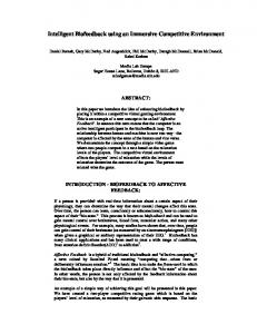
For systems with N coupled oscillators, the combined behavior of the coupled oscillators can be expressed as a superposition of the N normal modes of oscillation, each with iLs own natural frequency o,,. It is still possible to damp the motion of the oscillators by acting on each bunch as if it were a single oscillator [5,61. In this case the coupling to other bunches is represented in the driving term f(r) of the driven harmonic oscillator. Figure I presents the general form of a feedback controller applied to a dynamic system. This model shows a summing node, from which an error signal is generated, a feedback amplifier with complex gain A (w) , a second summing node which adds an external driving term F(o) , and a beam dynamics block with complex
Invited talk presented nf fhe lnfernafionul Conference on 13factories: The State uj fhr Art in Accelerators, Defectors and Physics, Stanford, C,4. April b-70. 7992
_
the oscillation frequency mp to a sampling frequency. If the beam is sensed at a single point in the orbit, any motion is sampled at the revolution frequency mIPY. If Ore”2 2W”, the Nyquist sampling limit is not exceeded and spectral information is not lost. As synchrotron frequencies are typically lower than revolution frequencies the sampling process does not alias the longitudinal oscillation frequency. However, in the transverse case bctatron frequencies are greater than revolution frequencies, and the sampling process aliases the oscillation to a different frequency. Thus, the transverse signal processing must operate at an aliased frequency, and be capable of operating over a range of aliased frequencies representing the machine betatron tune operating range.
transfer function H (0) . The beam response acts back on the input summing node, closing the feedback loop. A disturbance F (0) applied to the system is reduced through the feedback amplifier by the amount H (0) 1 +A (W)H(W)
so that it is desirable to have a large loop gain A (0) H (0) . However, the gain cannot be arbitrarily large or the loop will oscillate at a frequency where the net phase shift around the feedback loop is 2n7r and the magnitude of the loop gain A (0) H (0) is equal to unity; -This picture can be applied to an accelerator feedback system, in which case the external driving terms reflect excitations from outside disturbances, such as injection .. transients, other bunches’ coupling through ring imped..ances, or system noise. As the dynamics of the beam H (0) is determined by accelerator design, the challenge to the feedback designer is to specify A (0) so that the loop is stable, and the response to disturbances i; (0) is bounded and the transients well damped. The _. specification of A (0) , and the implementation of the feedback system has great importance for the ultimate equilibrium behavior of the closed loop system, and of the residual-noise in the system.
2. Signal Processing Options One of the most interesting design options for these systems are the technical choices involved in the error signal processing. This block has several essential functions: Detect the bunch oscillation. Provide a x/2 phase shift at the oscillation frequency. Suppress DC components in the error signal. Provide feedback loop gain at 0”. Implement saturated limiting on large oscillations. Provide processing gain, e.g., as the input signal may be noisy, apply processing techniques to reduce the noise ultimately put back onto the beam. These rcquiremcnts describe a bandpass filter, centered at the oscillation frequency oa, with some specified gain and a 7~12 phase shift at oO. DC rejection of the filter is necessary to keep the feedback system from attempting to restore a static equilibrium position to an artificial set-point. For example, a transverse static orbit offset from a pickup or from a true orbit offset should not result in the feedback system coherently kicking the beam in an aucmpt to force a new mean orbit. Similarly, if a ring has a ion clearing gap in a filling pattern, there will bc an RF transient which places the first bunches after the gap onto unique synchronous phases. In this case the longitudinal feedback system must restore oscillating bunches back to their own synchronous phases as opposed to a single common set point. This DC rejection constraint means that a simple time delay is not suitable for a feedback filter. The filter should also reject signals above the oscillation frequency to prevent noise or other high frequency signals from being mixed down into the filter passband and impressed unto the beam. The limiting function allows a bunch to have a large oscillation, larger than the available kicker power can rcstorc with linear operation, but still be kicked by a
This model, which treats each bunch as an independent oscillator coupled to its neighbors through an cxtcrnal driving term, is the heart of a bunch by bunch feedback system. This system implements a logically separate feedback system for each bunch in a multibunch accelerator 17-121. For accelerators with thousands of bunches, this approach requires that the implementation be compact, either by sharing some of the components between bunches (e.g., fast systems that are effectively time multiplexed between bunches) or by implementing parallel functions in a very efficient way (e.g., through electronic VLSI techniques). Both longitudinal and transverse feedback systems can be described by Fig, 1. For the transverse cast, the input set point is the desired orbit mean coordinate, and the oytput signal is applied via a transvcrsc clcctrode assembly which acts with a transverse kick on the beam. For the longitudinal case, the set point refers to the desired stable bunch phase or energy, and the correction signal is applied back on the beam to change the bunch energy. While longitudinal and transverse systems share a simple conceptual framework, the tcchni=Cal design,and implementation of these systems can be quite d&rent, -reflecting the actual dynamics of the beam and the signal processing techniques chosen. One fundamental difference between longitudinal and transverse accelerator feedback systems is the ratio 01 2
1
--’
I
I
I
I
I
acoustic wave (SAW) filter. Such an approach looks desirable in that a single device processes all bunches, but a typical B factory facility, with many bunches closely spaced and a synchrotron frequency in the 7-10 KHz range, would require a delay-bandwidth product beyond the commercial state of the art. Additionally, the fher parameters would be fixed by the lithography of the SAW, and any changein operating parameters that change the oscillation frequency (machine tune, RF voltage, lattice parameters, etc.) require a different physical SAW device. Another approach might use a charge coupled device (CCD) technology to implement the tapped delay line of a transversal filter, with analog multiplexing to select a particular bunch on selected turns, and an analog summing stage to implement a convolution filter. An electro-optical approach is also possible, in which an optical hbcr delay line can be used with passive or active taps to implement the convolution filter. However, these approaches suffer the same inflexibility of the SAW approach, and it is also difficult to implement a CCD system with the required delay-bandwidth product in a compact form. Such inflexible filters do not allow a single design to be shared among several facilities, Additionally, all of the analog based approaches do not simply implement the desired limiting function. A true limiter, with zero AM to PM conversion, is a specialized circuit at these frequencies, and would not offer a simple means to change the limiting value, or system gain, without much adjustment of circuit componcnls.
I.
Filter Coefficients
_
17
O’b T
I, I
-1
I
4
0 60
I
I
I
8 Discrete Time
-;
I
-20
I
I?‘-
12 (A.z=i’ps) I
I
20
16
I I Frequency Response
I
I
I
I
I
I
I
I
I
I
-
I
200
% E
.a
0
-200
0
0,
20
40
IO-92
Frequency
(KHz)
60 7272.42
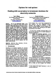
Impulse response (a) and frequency response (b) of a 20 tap FIR filter.
Figure2.
..
maximum kicker- held with the correct algebraic sign. This limited processing allows injection (and large amplitude excitation of the injected bunch) while still damping neighboring bunches in a linear regime. The saturated processing has been shown to suppress the growth of coherent instabilities from injection-like initial conditions [1,13]. For systems with only a few bunches to control one could implement the feedback lilters as individual analog bandpass filters [ 141. However, for systems with thousands of bunches a more efficient approach is to take advantage of the inherent sampling at mrev and implement the -filter as a convolution filter of either finite impulse response (FIR) or infinite impulse response (IIR) forms. An FIR filter is a convolution in the time domain
In contrast, digital signal processing techniques look very attractive as the means to implement the feedback filter. As the feedback process only uses information from a particular bunch to compute the feedback signal for that bunch, a parallel processing scheme is feasible. In this approach many processors operate in parallel, each processing a fraction of the total bunch population, and each keeping track of a group of bunches. This approach is particularly well matched to the commercial activity in digital signal processing microprocessors. The synchrotron frequencies are audio frequencies, so that processing blocks optimized for audio and speech applications serve very well as processing elements. These programmable components also offer the possibility of a general purpose feedback architecture which is configured via software to match the particular operating characteristics of an accelerator. A programmable and modular system allows a single design to be utilized by several facilities, and development costs to bc amortized over multiple feedback installations.
m-l ‘k
=
c
‘n’k-n
n=O
where Yk is the filter output on sample k, X, is the tiller input on sample k, and m is the length of the filter ( or number of past input samples used to generate an output). The coefficients Ci describe the impulse response of the filter in the time domain. Figure 2 shows the _ impulse .response and frequency response of a 20 tap FIR filt&&ptimized for a 7 KHz oscillation frequency. These filters can be realized by several approaches. An all-analog approach is possible, in which one might implement the required feedback filter as a surface 3
3. Functional Requirements
These functions must be performed in synchronism with the machine revolution frequency and bunch crossing frequency. For proposed bunch intervals of 2-4 ns, these functions must be implemented with electronic systems with adequate bandwidth to avoid creating multi-bunch coupling in the feedback system itself. We can estimate the required bandwidth of the total system by budgeting an allowable amount of interbunch coupling in the feedback system, and estimating the frequency response required. As an example, for the PEP11 4.2 ns bunch interval, and an allowable 5% (-26 dB) coupling, a first order system would require
A bunch-by-bunch time domain system with digital signal processing can be partitioned into major functional components comprising: l
Beam pickup-to transform motion of the beam into electrical signals.
9 Oscillation Detector-to into an error signal. l
l
.. l
process the pickup signals
Fast Error Digitizer-to convert each bunch’s error signal to a digital quantity. EaeGSignal processing-required to compute a correction signal to be applied to a bunch from the error signal. It may be useful to use information from several turns of a bunch’s error signal in each calculation.
or a total system 3 dB bandwidth of 226 MHz. As the overall response is the product of all the individual responses, achieving thcsc widcband functions requires car-c in design.
Fast D/A and Kicker Modulator-lo convcrl the computed error signals to an analog signal appropriate for the kicker stage.
4. PEP II Transverse Conceptual Design
: Power Amplifier-to generate the high power signal to be applied to the beam. l
Beam Kicker Structure-to to the beam.
x 1O-” In (0.05)
-4.2
T=
The PEP II transverse feedback system design (for one plane of motion) is ilhNrated in Fig. 3. The heart of this system is a quadrature phase shifter used to produce a
apply a correction signal
Kicker
Beam pickup n
D&m pickup l-l
Front-end block with difference, offset and gain correction
coefficient
r
Video D/A A/D
.
unver
Dual-bank hold buffer
Timing generator I
7059A70 Figure
3.
Block diagram of one plane of the PEP II transverse icedback system. 4
-
Beam pickup
1-5-z 7059A71 ; --
..
System Control
Timing lrom master oscillator
5. Block diagram of the PEP II longitudinal feedback system
Figure
Figure4. Block- diagram of the front end processing functions for the transverse system. The output of this block is a fast analog representation of the transverse bunch position.
to implement an error amplifier and phase shifter. Digital techniques are used to store a correction signal until the next pass of a bunch when it is applied back on the beam. The PEP II transverse system designers decided not to implement the feedback error amplifier as a digital hltcr process due to the difficulty in implementing a digital phase shifter for high crossing frequencies. As an example, if an all-digital phase shift was implementcd via a 3-tap FLR filter for a 500MHz crossin rate an aggregate multiply-accumulate rate of 1.5 x 10⁸ MACS/sec is required. Such a rate, plus the difficulty of maintaining the I/O bandwidth in such a system, led the designers to their mixed analog/digital design.
~12 phase shift of the beam oscillation signal. This quadrature phase shifter uses signals from two pickups (per plane) located roughly ~12 apart in betatron phase. From these sine and cosine channels it is possible to generate any required phase shift through the multipli. . cation and addition operations shown in the figure. Figure 4. shows the processing functions required for each pickup. The pickup design uses two stripline electrodes,.andfhe signals from the pickup are scaled via two multiplying digital to analog converters, subtracted in a difference hybrid, and filtered. A low bandwidth DC subtraction function is required to average the wideband position signal over many bunches, and adjust the multiplying coefficients to eliminate the DC component of the position signal. The output of this block is a wideband analog error signal representing the transverse displacement of each bunch.
5. PEP-II Longitudinal Conceptual Design Figure 5 shows the essential components of the proposed PEP II longitudinal feedback systems. This system uses a pickup and comb generator structure to generate a short (eight cycle) tone burst at the sixth harmonic of the ring RF frequency. This burst is multiplied (mixed) with the 6xRF reference, and the phase error signal digitized at the 238 MHz bunch crossing rate. A digital signal processing block is used to process the error signals, and a fast D/A is used to convert previously calculated feedback error signals and apply them to the bunches via a power amplifier and longitudinal kicker. The longitudinal kicker is a wideband drift tube structure that operates at 1.071 GHz. Table 1 summarizes technical spccilications for the longitudinal system, while more d&led system and component descriptions arc found in Ref. I1 I.
Referring to Fig. 3, this error signal is amplified and phase shifted via the quadrature coeflicients. The rotated signal is digitized and the error signal is held in a one turn hold buffer until the next revolution of that bunch. Thus; on a given turn an error signal is digitized for a bunch, while the previously computed error signal is taken from the hold buffer and applied to the bunch vja the D/A, kicker modulator, power amplifier and transverse kicker. The quadrature phase shifter provides for the generation of an error signal ,at an arbitrary phase with respect to the input signal. This scheme allows the ring to be operated at any fractional tune and allows the kicker to be located at any point in the ring. Reference [l] describes specifications for the transverse Systems-prmposedfor the PEP II design. The pr$osed components in ate an error (controlled via
The PEP II longitudinal system is designed as a digital processing system that takes advantage of the fact that the revolution frequency (sampling frequency) is greater than the synchrotron frequency. This inherent oversampling allows the use of downsampled processing, in which information about a bunch’s oscillation
riansverse design emphasizes analog the front end signal processing to genersignal, and uses analog techniques multiplying digital to analog converters) 5
_ coordinate is only used every n crossings, and a new correction signal is updated only every n crossings [15,16]. This approach allows the processing system to operate closer to the Nyquist limit and reduces the
number of multiply-accumulate operations in the feedback filter by a factor of 1 /n2. The PEP-II longitudinal system has been specified for a down- sampling factor of 4, while smaller rings (such as the ALS or the Frascati e factory DAoNE) would operate with downsampling factors of 24 or 16, respectively. The downsampled processing technique allows the use of arrays or “farms” of commercial single chip DSP microprocessors (such as the AT+T 1610) to very compactly implement feedback systems for thousands of bunches.
Table 1: Longitudinal Specifications Summary RF frequency [MHz]
476
Bunch interval [ns]
4.2
Beam pickup central frequency [MHz]
2856
Phaa detector dynamic range (at 476 Hz)
+1Y I
We can estimate the scale of this processing farm knowing the number of processing cycles required to compute a correction signal for a bunch, considering the cycles of processing “overhead” required per bunch (to maintain data lists, etc.) and knowing the synchrotron frequencies and number of bunches of a proposed accelerator. Table 2 estimates the scale of a DSP farm required for longitudinal feedback for the PEP II, ALS and DAeNE accelerators. These farms might be packaged as boards, each with 4 DSP processors, organized into crates of roughly 16 boards. As shown in Table 2, a B Factory processing system fits into two VME crates.
I
1 Phase detector resolution (at 476 Hz)
1
0.5“
1
rBunch-to-bunch
1
>30
I
.a
signal isolation [dB]
Kicker structure operating frequency @Hz1
I Output power [kWl
2.0
I( FIR tap length, m
I
Down-sampling factor, n
5
Figure 6 sketches the organization of such a processing farm based around a processing module containing four DSP processors. Only the fast front end, downsampler, hold buffer, and output stages must run at the fast beam crossing rate. The DSP processors run in parallel at a lower rate determined by the synchrotron frequency and the downsampling factor n. Note that this approach still kicks every bunch on every turn, and uses the kicker power cflicicntly.
I
4
Table 2: DSP Farm Scale for Three Accelerators Parameter Number of bunches
PEP11
ALS
1746
328
DAeNE 120
6. Implementation Progress and Laboratory Results 7’s Synchrotron period 1 1.4E-4 I7.9E-5 1 26E-6 [see’] 1 19.2 ) 121 Down-sampling factor Filter MACS/sec Overhead cycles/filter Overall processor cycleslsec
1
79.8
4
24
16
3E8
lE8
1.2E8
11
11
11
lE9
3.3E8
3.7E8
The proposed longitudinal system performance has been studied using a machine simulation model/ feedback system model code [ 13,171. This numeric simulation models the bunch to bunch coupling of higher order modes of the RF cavities and includes engineering lcvcl descriptions of the feedback components. With this model it is possible to explore operation of the ring in various conditions (injection, steady state, unequal bunch currents, etc.) and understand the impact of various electronic parameters (such as input noise, bunch to bunch coupling in the kicker or pickup, quantizing effects in the A/D and D/A stages, FIR filter coeflicients, ctc). This simulation model has been applied to produce system designs for the PEP II B factory, the LBL Advanced Light Source, and the Frascati e factory DAeNE [ 18,191.
1 1
A laboratory prototype longitudinal feedback system has been dcvclopcd at the Stanford Linear Accelerator 6
-
-
(4 RF Offset --t
I t (fr&?$%se detector)
Digitizer * and down-sampler
Centrol/diagnostrcs path
..
.
I $ -
t
Address generation
r
-
Dualor! t! old buffer
-xl-
!~,
t
1
7
Vernier >
* (to power amplifier)
DSP farm L
I
(b) Timing
* A,ng!J .
t H
Backplane 1 buffer/latch
I 1
zbr
Data/address path 1
4
Downsampler
Data/address
(c) .-
*
*
Control/ diagnostics path
Transfer
path
t
I w
Bus interface
Read/write select Address decoder and local interrupt generator
t
7059A69
.-
__-.-W Fi&re 6. Block diagram of (a) the digital signal processing in the longitudinal system, (b) the down sampling block, and (c) the four processor DSP module.
7
_
Center [20]. This lab model implements a full speed (500 MHz) front end phase detector with digital signal processing for a limited number of bunches. Beam tests of this system are expected to be conducted in the summer of 1992. A group at Lawrence Berkeley Laboratory has been developing the wideband longitudinal kicker and has a prototype lab model constructed 121I.
[6] R. D. Kohaupt, ‘Theory of Multi-Bunch Systems,” DESY 91-071.1991.
Feedback
[7] D. Heins et al., “Wide Band Multi-Bunch Systems for PETRA,” DESY 89-157,1989.
Feedback
]S] M. Ebcrt et al., “Transverse and Longitudinal Multi-Bunch Feedback Systems for PETRA,” DESY 91036, 1991. 191 P.Corrcdoura, J.-L. Pellegrin, H. D. Schwarz, and J. C. Sheppard, “An Active Feedback System to Control Synchrotron Oscillations in the SLC Damping Rings,” Proc. 1989 IEEE Part. Accel. Conf., p 1879.
7. Summary and Directions for the Future A working collaboration has been formed between workep at SLAC, LBL, INFN Frascati, and the Stanfbr~ Electrical Engineering department to jointly design and develop these next generation feedback systems. This group is completing the development of a longitudinal system prototype, based on the PEP II design, and is collaborating on the design of a trans. verse prototype. The goal of this group is to produce functional modules that may be used by several laboratories, and to develop modular and scaleable feedback system designs which use common hardware configured via software to specify the operating parameters of -a system. Results.from longitudinal system tests at the SLAC SPEAR and LBL ALS facilities are expected in fall ‘92 and early ‘93. * . .
[lo] M. Allen, M. Cornacchia, and A Millich,“A Longitudinal Feedback System for PEP,” IEEE Trans. Nucl. Sci. NS-26, no. 3, 1979, p. 3287. [ll]
E. Higgins,“Beam Signal Processing for the Fermilab Longitudinal and Transverse Beam Damping System,” IEEE Trans. Nucl. Sci. NS-22, no. 3, 1975, p. 1581.
1121 Ii. F. Steining and J. E. Griffin, “Longitudinal Instabilities in the Fermilab 400 GeV Main Accelerator,” IEEETrans. Nucl. Sci. NS-22, no. 3,1975, p. 1859. [13] D. Briggs et al.,“Computer Modelling of Bunch by Bunch Feedback for the SLAC B Factory Design,” Proc. 1EEE Part. Accel. Conf., 1991. T. Kinoshita, ]‘I41 T. Kasuga, M. Hasumoto, and H. Yonehara, “Longitudinal Active Feedback for UVSOR Storage Ring,” Japanese Jour. Applied Physics, Vol 27, no. 1, 1988, p. 100.
Acknowledgments The ideas discussed in this paper reflect the contributions of many people at SLAC, LBL, INFN Frascati and the Stanford Electrical Engineering Department. The authors also want to thank George Caryotakis, Jonathan Dorfan, Andrew Hutton, and Mike Zisman for-their support of the PEP-II feedback research and development activities.
llS1 H. Hindi et al., “Down-Sampled
Signal Processing for a B Factory Bunch-by-Bunch Feedback System,” Proc.1992 European Part. Accel. Conf.
1161H. Hindi et al., “Down-Sampled
Bunch-by-Bunch Feedback for PEP II,” these proceedings.
1171K. A. Thompson,
“Simulation of Longitudinal pled-Bunch Instabilities,” SLAC B Factory ABC-24, 1991.
References
CouNote
1181 0. Coin), A. Ghigo, and M. Serio, \lq\lq Longitudinal and Transverse Feedback,” DAQNE Machine Review, INFN Frascati, 1992.
111 “PEP-II An Asymmetric B Factory-Design Update,” Conceptual Design Report Update, SLAC, 1992. 121 B Factory Accelerator Task Force, S. Kurokawa, K. Satoh and E. Kikutani, Eds. “Accelerator Design of the KEK B Factory,” KEK Report 90-24,199l. - [31 “CESR-B Conceptual Design for a B Factory Based on CESR”, Cornell University, CLNS Report 911050,199l. _ -141 C. Pellegrini and M. Sands, “Coupled Bunch Longitu- i&&l Instabilities,” SLAC Technical Note PEP258, $ 977. ]51 A. Fetter and J. Walecka, ‘Theoretical Mechanics of Particles and Continua,” McGraw Hill, New York, 1980.
(191M. Bassctti,
0. Coiro, A. Ghigo, M. Migliorati, L. Palumbo, M. Serio, “DAoNE Longitudinal Feedback,” Proc. Third European Part. Accel. Conf., Berlin, Germany, 1992, p. 807.
ml D. Briggs ct al., “Prompt Bunch by Bunch Synchrotron Oscillation ment,” Proc. Instrumentation,
Detection by a Fast Phase MeasureWorkshop on Advanced Beam KEK, Vol. 2, 1991, p. 494.
]211 J. Byrd, J, Johnson, G. Lambertson, and F. Voelker, “Progress on PEP II Multibunch FLr?dback Kickers,” these proceedings.
8