JOURNAL OF DISPLAY TECHNOLOGY, VOL. 10, NO. 1, JANUARY 2014
43
Feedback Reversing Design Method for Uniform Illumination in LED Backlighting With Extended Source Dan Wu, Kai Wang, and Vladimir G. Chigrinov
Abstract—In light-emitting diode (LED) direct-lit backlighting application, it is a critical issue that how to design an optical component to achieve high uniform illumination with large distance–height ratio (DHR) and extended sources. A new feedback reversing design method is proposed to solve this problem, including calculation of feedback optimization ratios (FOR) to achieve uniform illumination for extended source and generate the required light intensity distribution freeform lens. According to this method, the uniformity of illuminance of LED extended source array increases from 0.54 to 0.85 significantly. Therefore, this new method provides a practical and simple way for optical design of LED uniform illumination with high DHR and extended source. Index Terms—Light-emitting diode (LED) displays, lighting control.
I. INTRODUCTION
L
IQUID crystal displays (LCDs) have been widely used in laptop computers, desktop monitors and high-definition televisions due to the advantages of high screen resolution, ultra brightness, low weight and slim profile. Various fluorescent lamps, such as cold cathode fluorescent lamp (CCFL), external electrode fluorescent lamp (EEFL), and flat fluorescent lamp (FFL), are adopted as LCD backlight sources. However, they are both bulky and high power consumption. Light-emitting diodes (LEDs), with increasing luminous efficiency and cost performance in recent years, have greater applications in backlighting for LCD [1]–[3]. Long life time, wide color gamut, and fast response time make LED backlighting, especially application in large scale LED TV, become the main driver force of LED marketing growth since 2010. Uniform illumination of LED array is crucial and is required by backlighting applications [4]. According to the light source position, there are two types of LED backlight, side-lit and direct-lit. Direct-lit backlight has the merits of size scalable and local dimmable which can improve the contrast ratio and lower the power consumption Manuscript received July 16, 2013; revised August 20, 2013; accepted August 20, 2013. Date of publication August 22, 2013; date of current version January 14, 2014. D. Wu and V. G. Chigrinov are with Center for Display Research, Department of Electronic and Computer Engineering, Hong Kong University of Science and Technology, Clear Water Bay, Kowloon, Hong Kong. K. Wang is with the Department of Micro-Nano Materials and Devices, South University of Science and Technology of China, Shenzhen, Guandong, China (e-mail:
[email protected]). Color versions of one or more of the figures are available online at http:// ieeexplore.ieee.org. Digital Object Identifier 10.1109/JDT.2013.2279406
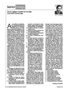
for LED TV. In this type of backlight, LEDs are mounted right below the LC panel. Uniform illumination from LED backlight will enable high image quality and therefore manufacturers have to adopt huge number of LEDs to achieve slim LED TV design. On the other hand, if we want to reduce the number of LEDs, the thickness should be increased to provide sufficient light mixing space to achieve uniform illumination. In this case, the LED TV will be bulky. A lot of research work has been conducted in this area. Moreno et al. proposed a method to achieve uniform illumination by optimizing the distance–height ratio (DHR) of LED array when the irradiance distribution of LED has an expression of [5], [6]. Zong et al. improved Moreno’s method making it also suitable when the light source has large view angle [7]. K. Wang et al. presented a reverse design method within which optimized light intensity distribution curve (LIDC) is generated and a free-form lens is built to realize the calculated LIDC. Their design can achieve uniformity with high distance height ratio (DHR) and reduce the number of LED packages considerably [8]. However, previous research work and algorithms were mainly built on the point source assumption and ignored the deterioration effect caused by the extended source. As shown in Fig. 1, high DHR and uniform illuminance at the target plane can be achieved for point source, but for extended source, the uniformity at the target plane will decrease. Uniformity represents the variance between the minimum and maximum illuminance and could be expressed as follows: (1) Besides , we also use coefficient of variation of root mean square error [i.e., CV(RMSE)] to measure the uniformity of the target plane, which is equal to the root mean square error (RMSE) divided by mean value of the illuminance as in (2). Comparing these two standards [10], U measures the maximum illuminance variation while can evaluate small illuminance variation across the target plane (2) The insert schematic pictures show that each light source is composed of a LED chip and a designed freeform lens. In Fig. 1, only the size of the LED chip changes and this leads to deterioration of illuminance uniformity. When and the size of LED chip increases from 0.28 mm 0.28 mm to 1 mm 1 mm,
1551-319X © 2013 IEEE. Personal use is permitted, but republication/redistribution requires IEEE permission. See http://www.ieee.org/publications_standards/publications/rights/index.html for more information.
44
JOURNAL OF DISPLAY TECHNOLOGY, VOL. 10, NO. 1, JANUARY 2014
Fig. 2. Schematic of the LED array and receiver plane.
illumination with LED extended source is proposed, including calculation of feedback optimization ratios (FOR) to achieve uniform illumination for extended source and generation of freeform lens with the required light intensity distribution. This method is practical and simple. High uniform illumination with extended source is achieved successfully when . The uniformity of LED extended source array enhances significantly by adopting this new design method. II. PROBLEM STATEMENT We extract a square LED array from a large number of LEDs as shown in Fig. 2. Each LED light source is defined as a LED package with a freeform lens. The distance between the centers of each two adjacent LED light sources is . We include a receiver plane to collect the energy emitting from LED light source and observe the light pattern. The distance between the receiver plane and the light source is set as . Commonly adopted denotes the ratio of adjacent light sources distance and the distance between the target plane and the light source. We will present a new feedback reversing design method to realize a high uniform lighting at the receiver plane with large DHR and high optical efficiency for extended source. III. DESIGN METHOD
Fig. 1. When , the average uniformity decreases with the light 0.28 source size increasing: (a) the size of light source is 0.28 mm , , (b) 0.4 mm 0.4 mm, , mm, and (c) 1 mm 1 mm, , .
drops from 0.89 to 0.54. increases from 0.02 to 0.15 with the increase of the size of light source. In our design, if the size of light source, specifically the LED chip size, will be larger or equal to 1/5 of the height of the lens, the light source belongs to the extended source category. Our design target is to achieve uniform illumination of a square LED extended source array with high DHR value. In this study, a new feedback reversing design method for uniform
The flow chart for our feedback optimization design method of uniform illuminance with extended source is shown in Fig. 3. First we use a design algorithm [8] to generate a freeform lens for point source uniform illumination at the target plane. Secondly, we replace the point source with extended source and calculate FOR. In the following, and represent the light intensity (LI) incident into lens from point source and extended source respectively. and represent the LI emit from the lens with point source and extended source. represents the optimized LIDC to achieve uniform illumination. As in (3), FOR is defined as the ratio of light intensity that emit from the lens and the optimized light intensity (3) In the next step, the FORs are applied to energy grids of light source, rebuild energy mapping relationship and a freeform lens for extended source is constructed. After that, our design is
WU et al.: UNIFORM ILLUMINATION IN LED BACKLIGHTING WITH EXTENDED SOURCE
45
Fig. 4. Schematic for light intensity distribution of light source.
Fig. 3. Flow chart for feedback optimization design method for extended source.
validated and optimized through ray tracing simulation until it meets our requirement. A. Design Method of Freeform Lens for Point Source Uniform Illumination First of all, we optimize a LIDC to meet the two uniform requirements on the target plane. Then we construct a freeform lens to generate the calculated LIDC. Finally we validate the whole design and realize uniform illumination for point source. Detail design method can refer to [8]. B. Design Method of Freeform Lens for Extended Source Uniform Illumination When we replace the point source with extended source, both the efficiency and the uniformity at the target plane are deteriorated. New design method for extended source uniform illumination will be proposed. Previously, for point source, we divide both the light source and the output energy into grids with equal energy. An energy mapping relationship is built between a couple of grids. However, this equal distribution of energy is no longer suitable for an extended source. We redistribute the energy for extended source by applying FORs on each energy grid and maintain the total energy conservation. The FORs are obtained by comparing simulation result of and . Based on the optimized grids division, we rebuild energy relationship between extended source and output light to reconstruct freeform lens. Simulation is performed and FORs are optimized until the results meet our requirement.
In this design method, the feedback optimization ratios acquisition, redivision of energy grids, and energy relationship establishment are three key steps, and the rest steps are similar with point source design method [8] which we do not discuss in details. In the following, we specifically describe the extended source freeform lens construction procedures. 1) Calculation of FOR: Since light source intensity distribution and the shape of lens for single LED package are all circular symmetrical, from Fig. 4 we know that changes from 0 to with is able to reflect the whole light intensity distribution. When the division number of grids is large enough, we can use , , and , to represent both the input and output light intensity of point source and extended source at given degree . FOR for each energy grid at given degree is set as which equals to the ratio of and as in (4) (4) We can only obtain limited LI values from the simulation result. These LI values, as a function of , can be provided with a limited degrees. In the simulation result, these degrees are restricted by the software but are not designed and selected according to the feedback optimization algorithm. As a result, these degrees are probably not in accordance with light source and output light intensity energy grid division degrees. In order to get at each desired , we use 10th order algebraic polynomial to fit , as specifically in (5) (5) 2) Energy Grids Division for Extended Source: As shown in Fig. 4, we set the total light energy of light source which is then divided into parts. Each part of the energy is . In the point source algorithm . According to spacial distribution of point source light intensity the unit conical object can be expressed with field angle in the latitudinal direction and in the longitudinal direction. By the following expression (6), we can calculate the . Since the LIDC of light
46
JOURNAL OF DISPLAY TECHNOLOGY, VOL. 10, NO. 1, JANUARY 2014
According to light source energy division method, we can obtain emitting angles of an optimized light source grid with (10).
(10)
Fig. 5. Energy mapping relationship between input and output light.
source is circular symmetrical, (6) can be simplified as (7) and the total luminous flux of the light source can be described as (8). In this case, we can calculate the th energy map by (9). (6)
(7)
means before optimization the lumiAmong them, nous flux of each point source grid, in other words ; represents the first emitting light ray direction which is vertical pointed and the value is 0. In this way, we can build energy mapping relationship between the newly divided light source and the target plane. 3) Construction of Freeform Lens for Extended Source: Since we have obtained the emitting directions of input rays and the corresponding exiting directions of output rays, it is easy to design a freeform lens to meet this mapping relationship according to the edge ray principle, Snell’s law and surface lofting method [9]. 4) Ray Tracing Simulation and Circulation Feedback Optimization: We analyze the light pattern illuminance of extended source with the new designed freeform lens. If the evaluation results satisfy our preset standards, we accept the design; otherwise, we circulate more times to optimize the design until the results satisfy the illuminance requirements. IV. DESIGN EXAMPLE
(8) (9) For extended source, each grid energy is equal to . The directions of rays, which define the boundary of one sub-source , have been also calculated as and . We divide the output light energy into parts with equal energy. Based on the function (4), we can transfer the energy mapping relationship to the LI mapping as shown in Fig. 5. Correspondingly, by Snell’s Law, we know each grid output light energy . Rebuild the energy mapping relationship and design freeform lens for extended source. In this method, after the first time optimization of grids’ division, the th grid luminous flux of light source is changed into . However, during the second time optimization, FOR possess different values from the first time. Meanwhile, each grid of light source is optimized based on the first time optimized result instead of the original point source grids evenly division. To easily illustrate and understand, we introduce subscript to represent the times of optimization. Light source grids and corresponding FORs are expressed as follows: , and . For example, we use to represent the changing ratios of the second times optimization applied on the third grid of light source.
There are two types of LED backlighting, side-lit and direct-lit. With limitation by the light transport distance in light guide plate (LGP), side-lit is not suitable for large or ultra large LED backlighting. Direct-lit has advantages size scalable and local dimming which could enhance contrast ratio and decrease power consumption for LED TV. Therefore direct-lit probably will become the develop trend for ultra large LED backlighting. Fig. 6(a) shows an optical model of a LED package which includes a substrate, a LED chip, and a freeform lens. The height of our freeform lens generated by our feedback design method is 1.8 mm and the refractive index is 1.54. This lens can be easily manufactured by molding process. The size of LED chip varies from 0.28 mm 0.28 mm to 1 mm 1 mm which is larger than 1/5 of the height of freeform lens and therefore are considered as extended source. As shown in Fig. 6(b), distance between square LED modules array and the receiving plane is 10 mm and the distance between each adjacent LED light sources is 30 mm. Considering periodical distribution of LED modules array, an area with the size of 6 6 LEDs array on the receiving plane is set as the testing area, which is able to reflect the whole lighting performance on the target plane. In addition, since a part of lights emitted by the outside LED modules will be reflected by the reflection box in the side walls, only the uniformity of illuminance of central area of 4 4 LED modules array is considered in this design. First of all, we calculated the uniform illumination LIDC according to the two criterions and the expression is . Freeform lens for point source is generated. The simulation
WU et al.: UNIFORM ILLUMINATION IN LED BACKLIGHTING WITH EXTENDED SOURCE
47
Fig. 8. Illuminance distribution of LED array consists of 1 mm 1 mm extended chip size LEDs at the receiver plane.
Fig. 6. LED array with extended source: (a) single LED light source and (b) LED array optical model.
Fig. 9. Illuminance distribution of LED array consists of 1 mm 1 mm extended chip size LEDs with feedback optimized freeform lens at the receiver plane.
Fig. 7. Illuminance distribution of 0.28 mm 0.28 mm point source LED array at the receiver plane.
results in Fig. 7 show that when , the point source algorithm is able to produce uniform illumination at the target plane by adopting point source with size of 0.28 mm 0.28 mm. The value of and are calculated through sampled points. The results show that and . For most lighting application, if belongs to 0.85 to 1.15, the design satisfies the requirements and we accept the design. This step guarantee a uniform illumination is obtained for point source. The optical efficiency is defined as the optical energy emitted from the freeform lens divided by that incident into the lens. As for 0.28 mm 0.28 mm point source, simulation result show the optical efficiency is 91%.
Secondly, we replace the point source with 1 mm 1 mm extend source and rerun the simulation. From Fig. 8, we can find the decreases to 0.54 and increases to 0.15. This uniform deterioration is caused simply by the size of LED chip. Fig. 8 shows obvious light spot which is the LED light source location. The optical efficiency is 86%. Thirdly, we calculate the FORs. Normalization of both and , we calculate the FORs at various degrees. Then FORs are fit by10th order algebraic polynomial . Therefore, at each given we can easily obtain corresponding FOR value. We apply these FORs to build a new freeform lens for extended source and run simulation to test the result. In Fig. 9, we can find that the uniformity is improved greatly. increases to 0.85 and decreases to 0.04. Besides, the optical efficiency increases to 91%.
48
JOURNAL OF DISPLAY TECHNOLOGY, VOL. 10, NO. 1, JANUARY 2014
[5] I. Moreno, “Configurations of LED arrays for uniform illumination,” in Proc. SPIE, 2004, vol. 5622, pp. 713–718. [6] I. Moreno et al., “Designing light-emitting diode arrays for uniform near-field irradiance,” Appl. Opt., vol. 45, no. 10, pp. 2265–2272, 2006. [7] Z. Qin et al., “Analysis of condition for uniform lighting generated by array of light emitting diodes with large view angle,” Opt. Express, vol. 18, no. 16, pp. 17460–17476, 2010. [8] K. Wang et al., “New reversing design method for LED uniform illumination,” Opt. Express, vol. 19, no. S4, pp. A830–A840, 2011. [9] K. Wang et al., “Design of compact freeform lens for application specific light-emitting diode packaging,” Opt. Express, vol. 18, no. 2, pp. 413–425, 2010. [10] I. Moreno, “Illumination uniformity assessment based on human vision,” Opt. Lett., vol. 35, p. 4030, 2010.
Fig. 10. Light intensity distributions before and after application of feedback optimization method.
The light intensity distribution of single LED light source before and after feedback reversing design method is shown in Fig. 10. The energy emitting from the light source is redistributed. Optical energy from 30 to 30 is reduced by the feedback reversing method which leads to uniform illuminance distribution at the receiver plane. V. CONCLUSION A feedback reversing design method for uniform illumination in LED backlighting with extended source has been verified through simulation. Good lighting performance in terms of high illuminance uniformity when is achieved. We can find that the uniformity deterioration of illuminance caused by extended source on the receiving plane is greatly improved, achieving and from and . Therefore, uniform illumination is able to be achieved easily by this new method when DHR is much larger than 1. Consequently, this reserving design method provides an effective way to overcome the extended source problem and to achieve high uniform illumination in LED backlighting with extended source. REFERENCES [1] M. G. Craford, “LEDs for solid state lighting and other emerging applications: Status, trends, challenges,” in Proc. SPIE, 2005, vol. 5491, pp. 1–10. [2] E. F. Schubert, Light-Emitting Diodes. New York, NY, USA: Cambridge Univ. Press, 2006, pp. 15–64. [3] S. Liu, LED Packaging for Lighting Applications: Design, Manufacturing and Testing. Hoboken, NJ, USA: Wiley, 2011, pp. 113–135. [4] C. C. Sun et al., “Brightness management in a direct LED backlight for LCD TVs,” J. SID, vol. 16, p. 519, 2008.
Dan Wu received the B.S. degree from School of Astronautics, Harbin Institute of Technology, in 2009, and the M.S. degree in optical engineering from the Huazhong University of Science and Technology, in 2011. Since 2011, she is with The Hong Kong University of Science and Technology, Clear Water Bay, Kowloon, Hong Kong, where she is engaged in improving the lighting performance of LED backlighting.
Kai Wang received the Ph.D. degree from Wuhan National Laboratory for Optoelectronics (WNLO), Huazhong University of Science & Technology (HUST), in 2011. In 2013, he joined the Department of Micro-Nano Materials and Devices, South University of Science and Technology of China (SUSTC), as an Assistant Professor. He was a V.P. of Guangdong Real Faith Optoelectronic Company, Ltd. He developed a series of new algorithms of freeform optics for various LED products, including application specific LED package (ASLP), LED street lamp, large-scale LED backlighting, LED headlamp of automotive, etc., and provided an effective way to achieve high quality LED lighting. His research interests include solid state lighting (SSL), freeform optics for SSL, display and solar energy, LED micro optics and advanced LED packaging and applications.
Vladimir G. Chigrinov received the Ph.D. degree in solid state physics from Shubnikov Institute of Crystallography, U.S.S.R. Academy of Sciences, in 1978. In 1988, he defended the doctoral degree and became a Professor in Shubnikov Institute of Crystallography also in 1988, where he had been a Leading Researcher since 1996. He joined Hong Kong University of Science and Technology (HKUST), Hong Kong, in 1999, and is currently Associate Professor. He has written 2 books, 14 reviews and book chapters, 166 refereed papers, and 41 patents in the field of liquid crystals since 1974. Dr. Chigrinov is a member of Editorial Board of Liquid Crystal Today and is the Vice-President of Russian SID Chapter.