APPLIED PHYSICS LETTERS
VOLUME 79, NUMBER 6
6 AUGUST 2001
Femtosecond laser interference technique with diffractive beam splitter for fabrication of three-dimensional photonic crystals Toshiaki Kondo, Shigeki Matsuo,a) Saulius Juodkazis, and Hiroaki Misawa Faculty of Engineering, The University of Tokushima, 2-1 Minamijosanjimacho, Tokushima 770-8506, Japan
共Received 2 April 2001; accepted for publication 11 June 2001兲 A simple optical interference method to fabricate microperiodic structures was demonstrated. Femtosecond laser pulse was split by a diffractive beam splitter and overlapped with two lenses. Temporal overlap of the split femtosecond pulses, which requires 10 m order accuracy in optical path lengths, was automatically achieved by this optical setup. One-, two-, and three-dimensional periodic microstructures with micrometer-order periods were fabricated using this method. © 2001 American Institute of Physics. 关DOI: 10.1063/1.1391232兴
A photonic crystal 共PhC兲 is an artificial structure whose refractive index is periodically modulated. A PhC can alter the propagation property of light with a wavelength of roughly twice that of its period.1 Due to its promising applications such as integrated optical circuits and thresholdless lasers, PhCs have been intensively investigated.2,3 The fabrication of PhCs which work in the visible or near-infrared range is still a challenging topic. The principal method involves semiconductor fabrication technology, which includes lithography, layering, and etching processes. Several sophisticated methods have been developed,4,5 but they require expensive and large-scale equipment. Other techniques have also been investigated such as laser microfabrication6,7 and self-organization of 8 –10 microspheres. The laser interference technique is also applicable for the fabrication of PhCs, because it produces a periodically modulated optical intensity with a period in the order of its wavelength. The interference of two beams creates a one-dimensional 共1D兲 periodic pattern. By increasing the number of beams, in principle, two-dimensional 共2D兲 and three-dimensional 共3D兲 periodic patterns can be designed. Burns et al. have demonstrated an interference technique for arranging small particles into 2D periodic patterns.11 If periodically modulated optical intensity is transferred to a photoreactive material, a PhC is obtained. Campbell et al. have made fcc-type 3D PhC structures in photoresist by overlapping four nanosecond pulses.12 Shoji et al. used five cw beams, which resulted in a hexagonal structure of photopolymerizable resin.13 These are remarkable accomplishments; however, a complicated optical setup is required for the interference of multiple laser beams, and its precise adjustment is difficult. In this letter we demonstrate the fabrication of PhCs using multibeam laser interference with a simple optical setup based on a diffractive beam splitter 共DBS兲. The setup is easily applicable for the interference of femtosecond pulses. The images of multidimensional periodic structures fabricated by this method are presented. The optical setup is schematically shown in Fig. 1. A DBS, which is the key element of this setup, splits the introa兲
Electronic mail:
[email protected]
duced laser beam into several. The split beams are made parallel by a lens, L1, then selected by an aperture array to obtain an aimed interference pattern. The selected beams are gathered by a lens, L2, and create interference at the focused region, where the sample 共photoreactive material兲 is placed. The distance between L1 and L2 was adjusted to make each beam plane wave after the L2. The DBS used was G1029A 共MEMS Optical, Inc.兲. It splits the input beam into nine beams; in this study only five of them ( ␣ ,  , ␥ , ␦ , and ⑀ ) were used, as shown in Fig. 1. The combinations of the beams used in the present study are summarized in Table I. The angle air is determined by the DBS, L1, and L2. An achromatic lens 共Edmond J32883, f ⫽175 mm兲 was used as L1 and an objective lens 共Olympus Uapo/340兲 was used as L2; so that the air was about 24.7°. As seen in the figure, the angle changes to s in the sample according to Snell’s law. The intensity of the central beam, I ⑀ , was about 20 times larger than that of the other beams. Since the ideal value of this ratio is 4 for the beam set B3, a homemade filter was used which reduce only the intensity of I⑀ . The second harmonic of femtosecond pulses 共380 nm, 80 fs, 82 MHz兲 was used as an irradiation source for fabrication. Irradiation power and duration were adjusted to obtain clear periodic structures: typically about 100 W 共sum of all irradiated beams兲 and 20 s, respectively. No adjustment for the pulses’ temporal overlap was performed. The sample
FIG. 1. Optical setup. DBS: diffractive beam splitter, L1 and L2: lenses, and AA: aperture array. The inset shows beam configuration around the sample.
0003-6951/2001/79(6)/725/3/$18.00 725 © 2001 American Institute of Physics Downloaded 03 Aug 2001 to 128.113.4.120. Redistribution subject to AIP license or copyright, see http://ojps.aip.org/aplo/aplcr.jsp
726
Kondo et al.
Appl. Phys. Lett., Vol. 79, No. 6, 6 August 2001
TABLE I. Selection of beams. Name
Selected beams
B1 B2 B3
␣,  ␣, , ␥, ␦ ␣, , ␥, ␦, ⑀
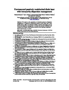
material used to make PhCs is a negative photoresist SU-8 共Microlithography Chemical Corp.兲. It was spin coated on a glass plate forming about a 25-m-thick film, and prebaked before irradiation. After irradiation, it was postbaked and developed. Periodic structures were eventually obtained. For observation of the fabricated structures, an optical microscope 共Olympus IX-70兲 and a scanning confocal microscope 共Zeiss LSM-410兲 were used. The confocal microscope was adopted to reveal the 3D structures inside the fabricated region. For that case, a small amount of dye 共Rhodamine 6G兲 was added into the photoresist before exposure and luminescence from the dye contaminated in the solidified resin was detected. By the beam set B1, the interference of two beams, a grating-like 1D periodic structure was obtained 共not shown兲. Theoretically, the period corresponds to the difference in wave vectors of the two beams, i.e., s /2 sin s ⫽air /2 sin air where s and air are the wavelength of the laser in air and in the sample. The experimentally obtained period was about 500 nm. This value is in agreement with the calculated value of 460 nm. This agreement indicates the periodic structure was in fact fabricated by the interference of the two laser beams. In the case of four beams, the beam set B2, a 2D periodic structure is expected. The image of the obtained structure 共top view兲 is shown in Fig. 2共a兲. As seen, a four-fold symmetric structure was fabricated. The period was about 700 nm. This is in agreement with the calculated value of s /(& sin s)⫽640 nm. Figure 2共b兲 shows the cross section of the structure. It should be noted that if the exposure dose was not sufficient, a part of the resin was solidified, but the whole structure was not self-supporting enough to withstand the development procedure. The intensity profile of four beam interference I is calculated as I⫽ 具 兩 E ␣ ⫹E  ⫹E ␥ ⫹E ␦ 兩 典 , 2
where E ␣ ⫽E 0 cos共 k cos z⫺k sin x⫺ t⫹ ␣ 兲 , E  ⫽E 0 cos共 k cos z⫹k sin x⫺ t⫹  兲 ,
共1兲
FIG. 3. Calculated intensity distribution by the interference of four beams with different relative phases, 共a兲 all the beams have same phase, and 共b兲 phase of one beam is shifted by .
E ␥ ⫽E 0 cos共 k cos z⫺k sin y⫺ t⫹ ␥ 兲 , E ␦ ⫽E 0 cos共 k cos z⫹k sin y⫺ t⫹ ␦ 兲 , where k and are the wave vector and angular frequency of the beam, respectively, E 0 is the constant of electric field strength, and ␣ ,  , ␥ , and ␦ are the phases of the beams.14 The intensity profile I does not depend on z. In the simple case of i ⫽0 (i⫽ ␣ ,  , ␥ , ␦ ), the intensity profile is I⫽2 兩 E 0 兩 2 关 cos共 k sin s x 兲 ⫹cos共 k sin s y 兲 其 2 ,
共2兲
which is shown in Fig. 3共a兲. It is four-fold symmetric, and the distance between adjacent peaks is s /( 冑2 sin s). This intensity profile varies with . For example, in the case of ␣ ⫽  ⫽ ␥ ⫽0 and ␦ ⫽ : I⫽2 兩 E 0 兩 2 关 cos2 共 k sin s x 兲 ⫹cos2 共 k sin s y 兲兴 .
共3兲
This calculated intensity profile is shown in Fig. 3共b兲. As seen, it is also four-fold symmetric but its number of peaks is double and the distance between adjacent peaks are s /2 sin s , which is 1/& of 共a兲. In our experiments, however, structures with a period about s /(& sin s) 关Fig. 3共a兲兴 were obtained exclusively. This is explained as follows. In general, the intensity I 关Eq. 共1兲兴 can be expressed as
冋 冉 冉
I⫽2 兩 E 0 兩 2 cos2 Ax⫹ ⫹2B cos Ax⫹
冊 冉 冊 冊 冉 冊册
␣⫺ ␥⫺␦ ⫹cos2 Ay⫹ 2 2
␣⫺ ␥⫺␦ cos Ay⫹ 2 2
,
共4兲
where A⫽k sin s and B⫽cos关„␣ ⫹  ⫺( ␥ ⫹ ␦ )…/2兴 . Ignoring the position of the peaks, the profile is determined only by the factor B. The intensity of the two type peaks 关peaks P1: appear in 共a兲, and peaks P2: appear only in 共b兲兴 is 1⫹B and 1⫺B, respectively. Only in the case when B is strictly equal to zero, the intensities at the P1 and P2 are identical so that structure similar to Fig. 3共b兲 is fabricated. In the most cases, B is not equal to zero, thus the intensities at P1 and P2 are different. The less distinct peaks tend to disappear through the development process. Accordingly, structures similar to 共a兲 were obtained exclusively. Further control of optical phases would allow the creation of a structure similar to that shown in 共b兲. For both beam sets B1 and B2 共Table I兲, the structures were basically independent of the depth; that is, the same structure was observed in any xy plane. This is because the used beams ( ␣ ,  , ␥ , ␦ ) have the same wave vector in the z
FIG. 2. Image of the structure fabricated by the beam set B2, 共a兲: xy cross section and 共b兲: xz cross section. Downloaded 03 Aug 2001 to 128.113.4.120. Redistribution subject to AIP license or copyright, see http://ojps.aip.org/aplo/aplcr.jsp
Kondo et al.
Appl. Phys. Lett., Vol. 79, No. 6, 6 August 2001
727
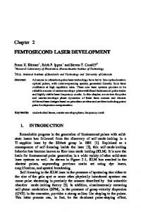
ment. A femtosecond laser is preferable for two-photonabsorption fabrication, which is a powerful technique to make micro-3D structures.15,16 The present method could be applied to two-photon interference fabrication. In conclusion, we have demonstrated a laser interference method to make 1D, 2D, and 3D periodic structures. This method has advantages of simple optical setup and flexibility in structure through the choice of interfering beams. FIG. 4. Image of the structure fabricated by the beam set B3, 共a兲 xy cross section and 共b兲 xz cross section.
axis. However, the central beam ⑀ has a different wave vector in the z axis. As a result, in the case of B3 ( ␣ ,  , ␥ , ␦ , and ⑀ ) the obtained structure was periodic in the z axis as well as in the x and y axes. Figure 4 shows the structures fabricated by the beam set B3, in which the beam ⑀ was added to B2. Figure 4共a兲 is an xy cross section. It is also four-fold symmetric, but in the middle of the four peaks some solidified objects are seen in the underlayer. This suggests that a 3D periodic pattern was fabricated. The periodicity in z is more clearly seen in Fig. 4共b兲, which is a zx cross section of the structure. The advantage of the interference method is its ability to create a periodic structure of large volume through an irradiation process, as well as the uniformity of period. Using a laser microfabrication technique, Sun et al.6 and Cumpston et al.7 have reported the fabrication of 3D PhC structures. In those cases, the structures were fabricated step by step through precisely scanning the sample, therefore requiring much longer time. In addition, the optical setup of the present method is quite simple 共the number of optical elements is small兲, as a result it is stable and easy to adjust. Furthermore, the present method is suitable for the interference of femtosecond pulses. Usually precise adjustments of optical delay are required for each optical path to obtain the temporal overlap of femtosecond pulses, but in the present setup temporal overlap was achieved without any adjust-
This work was supported by a Grant-in-Aid for Encouragement of Young Scientists 共No. 12750221兲 from the Japan Society for the Promotion of Science, and the Satellite Venture Business Laboratory of the University of Tokushima. E. Yablonovitch, J. Opt. Soc. Am. B 10, 283 共1993兲. Photonic Crystals, edited by J. D. Joannopoulos, R. D. Meade, and J. N. Winn 共Princeton University Press, Princeton, NJ, 1995兲. 3 Technical Digest of PECS2000 and references therein. 4 O. Hanaizumi, K. Miura, M. Saito, T. Sato, S. Kawakami, E. Kuramochi, and S. Oku, IEICE Trans. Electron. 83C, 912 共2000兲. 5 S. Y. Lin, J. G. Fleming, E. Chow, J. Bur, K. K. Choi, and A. Goldberg, Phys. Rev. B 62, R2243 共2000兲. 6 H.-B. Sun, S. Matsuo, and H. Misawa, Appl. Phys. Lett. 74, 786 共1999兲. 7 B. H. Cumpston, S. P. Ananthavel, S. Barlow, D. L. Dyer, J. E. Ehrlich, L. L. Erskine, A. A. Heikal, S. M. Kuebler, I.-Y. S. Lee, D. MccordNaughton, J. Qin, H. Ro¨kel, M. Rumi, X.-L. Wu, S. R. Marder, and J. W. Perry, Nature 共London兲 398, 51 共1999兲. 8 A. V. Blaaderen, R. Ruel, and P. Wiltzius, Nature 共London兲 385, 321 共1997兲. 9 K. Fukuda, H.-B. Sun, S. Matsuo, and H. Misawa, Jpn. J. Appl. Phys., Part 2 37, L508 共1998兲. 10 H. Miguez, F. Meseguer, C. Lo´pez, M. Holgado, G. Andreasen, A. Mifsud, and V. Forne´s, Langmuir 16, 4405 共2000兲. 11 M. M. Burns, J.-M. Fournier, and J. A. Golovchenko, Science 249, 749 共1990兲. 12 M. Campbell, D. N. Sharp, M. T. Harrison, R. G. Denning, and A. J. Turberfield, Nature 共London兲 404, 53 共2000兲. 13 S. Shoji and S. Kawata, Appl. Phys. Lett. 76, 2668 共2000兲. 14 Some submicrometer difference in optical path lengths could be present, thereby the phases were introduced in calculation. 15 S. Maruo and S. Kawata, J. Microelectromech. Syst. 7, 411 共1998兲. 16 M. Miwa, S. Juodkazis, T. Kawakami, S. Matsuo, and H. Misawa, Appl. Phys. A 共accepted for publication兲. 1 2
Downloaded 03 Aug 2001 to 128.113.4.120. Redistribution subject to AIP license or copyright, see http://ojps.aip.org/aplo/aplcr.jsp