feature points. As a specific application, we describe the use of the algorithm for MPEG-4 facial mesh deformation and animation. The MPEG-4 face object.
FEATURE POINT BASED MESH DEFORMATION APPLIED TO MPEG-4 FACIAL ANIMATION
Sumedha Kshirsagar, Stephane Garchery, Nadia Magnenat-Thalmann MIRALab, CUI, University of Geneva
Key words:
mesh deformation, real-time facial animation, performance driven animation, optical tracking
Abstract:
Robustness and speed are primary considerations when developing deformation methodologies for animatable mesh objects. The goal of this paper is to present such a robust and fast geometric mesh deformation algorithm. The algorithm is feature points based i.e. it can be applied to enable the animation of various mesh objects defined by the placement of their feature points. As a specific application, we describe the use of the algorithm for MPEG-4 facial mesh deformation and animation. The MPEG-4 face object is characterized by the Face Definition Parameters (FDP), which are defined by the locations of the key feature points on the face. The MPEG-4 compatible facial animation system developed using this algorithm can be effectively used for real time applications. We extract MPEG-4 Facial Animation Parameters (FAP) using an optical tracking system and apply the results to several synthetic facial mesh objects to assess the results of the deformation algorithm.
1.
INTRODUCTION
In this paper, we present a robust, fast, and simple geometric mesh deformation algorithm. A geometric mesh can be characterized by the locations of key feature points. Further, the animation of the mesh can be defined by the displacements of these feature points. The algorithm described here can be applied for animation of such meshes. As a specific application, we describe the use of the algorithm for MPEG-4 facial mesh, which is characterized by the Face Definition Parameters (FDP). We examine the results of the mesh deformation applied to facial animation by 1
2
Sumedha Kshirsagar, Stephane Garchery, Nadia M.-Thalmann
using the Facial Animation Parameters (FAP) obtained from an optical tracking system used for facial feature capture. There are a variety of ways possible to represent animatable objects geometrically. The choice depends on the considerations such as precise shape, effective animation and efficient rendering. Barr introduced geometric modeling deformations using abstract data manipulation operators creating a useful sculpting metaphor [1]. Bearle applied surface patch descriptions to model smooth character form [2]. Free Form Deformation (FFD) and its variants have been used extensively for a variety of modeling and animation applications [3][4][9][13]. They involve the definition and deformation of a lattice of control points. An object embedded within the lattice is then deformed by defining a mapping from the lattice to the object. FFDs allow volume deformation using control points while keeping the surface continuity. They provide the sculptural flexibility of deformations. FFDs have been successfully used for synthetic objects like face [6] and hand deformation [11]. FFDs have some limitations though. The locations of the control points are not very well controllable with respect to the actual mesh object. Also, the discontinuities or holes in the mesh are difficult to handle as a general case. Recently, Singh et. al.[15], proposed a new approach of using wire curves to define an object and for shaping its deformation. They illustrated the applications of animating figures with flexible articulations, modeling wrinkled surfaces and stitching geometry together. In order to define shape and animation of a geometric mesh object, we concentrate on the use of feature points. We assume that the shape of the object is defined by the locations of the predefined feature points on the surface of the mesh. Further, the deformation of the mesh can be completely defined by the movements of these feature points (alternatively referred as control points) from their neutral positions either in absolute or in normalized units. This method of definition and animation provides a concise and efficient way of representing an object. Since the control points lie on the geometric surface, their locations are predictable, unlike in FFD.
2.
GEOMETRIC MESH DEFINITION AND DEFORMATION
In this section, we describe in detail the feature point based mesh deformation algorithm. The algorithm is usable on any generic surface mesh. To begin with, the feature points or the control points with movement constraint are defined for a given mesh. A constraint in a direction indicates the behaviour of the control point in that direction. For example, if a control
Feature Point Based Deformation for MPEG-4 Facial Animation
3
point is constrained along the x axis, but not along the y and z axes, means that it still acts as an ordinary vertex of the mesh along the y and z axes. Its movement along these axes will be controlled by the other control points in the vicinity. Given a geometric mesh with control point locations, we need to compute the regions influenced by each of the control points. In order to get realistic looking deformation and animation, it is necessary that the mesh has a good definition of the feature points; i.e. the control point locations should be defined considering the animation properties and real-life topology of the object under consideration. Each vertex of the mesh should be controlled by not only the nearest feature point, but other feature points in the vicinity, in order to avoid patchy animation. The number of feature points influencing a vertex and the factor by which each feature point influences the movement of this vertex is decided by the following: • The distances between the feature points i.e. if the feature points are spread densely or sparsely on the mesh • The distances between the ordinary (non-feature point) vertices of the mesh and the nearest feature point • The relative spread of the feature points around a given vertex The algorithm is divided into two steps. In the Initialization step, the above mentioned information is extracted and the coefficients or weights for each of the vertices corresponding to the nearest feature points are calculated. The distance between two points is computed as the sum of the edge lengths encountered while traversing from one point to the other. We call this surface distance. This surface distance measure is useful to handle holes and discontinuities in the mesh, e.g. mouth and eye openings in the facial mesh models. The Deformation step actually takes place during the real-time animation for each frame.
2.1
Initialization
The initialization can further be divided into two substeps. 2.1.1
Computing Feature Point Distribution
In this step, the information about all the neighbouring feature points for each of the feature point is extracted. The mesh is traversed starting from each feature point, advancing only one step in all the possible directions at a time, thus growing a mesh region for each feature point, called feature point region. Neighbouring feature points are those feature points that have a common feature point region boundary. As a result, for each feature point
4
Sumedha Kshirsagar, Stephane Garchery, Nadia M.-Thalmann
defined on the mesh surface, we get a list of the neighbouring feature points with surface distances between them. This information is further used in the next step. 2.1.2
Computing Weights
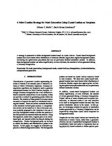
The goal of this step is to extract possible overlapping influence regions for each feature point and to compute the corresponding weight for deformation for all the vertices in this influence region. Consider a general surface mesh as shown in Figure 1. During the process of mesh traversal starting from the feature points, assume that the vertex P is approached from a feature point FP1. FP1 is added to the list of the influencing feature points of P.
Figure 1. Computing weights for animation
From the information extracted in the previous step of mesh traversal, FP2, and FP3 are the neighbouring feature points of FP1. FP2 and FP3 are chosen such that the angles θ2 and θ3 are the smallest of all the angles θi for neighbouring feature points FPi of FP1. Also, π π θ2 < ,θ3 < 2 2
(1)
The surface distances of the vertex from these feature points are respectively d1P, d12 and d13 as shown in the figure. While computing the weight of FP1 at P, we consider the effect of the presence of the other neighbouring feature points namely FP2 and FP3 at P. For this, we compute the following weighted sum d:
Feature Point Based Deformation for MPEG-4 Facial Animation d=
d12 cosθ2 + d13 cosθ3 cosθ2 + cosθ3
5
(2)
Thus, d is the weighted sum of the distances d12 and d13. The feature point in a smaller angular distance from the FP1 is assigned a higher value of weight. If there is only one neighbouring feature point of FP1 such that θ2