two basic iteration algorithms for multicomponent dis- tillation design, which are based on .... of column design using the theory of distillation trajec- tory bundles.
Theoretical Foundations of Chemical Engineering, Vol. 35, No. 3, 2001, pp. 224–236. Translated from Teoreticheskie Osnovy Khimicheskoi Tekhnologii, Vol. 35, No. 3, 2001, pp. 239–251. Original Russian Text Copyright © 2001 by Petlyuk, Danilov.
Few-Step Iterative Methods for Distillation Process Design Using the Trajectory Bundle Theory: Algorithm Structure F. B. Petlyuk and R. Yu. Danilov ECT-Service Research and Engineering Firm, Protopopovskii per. 25b, Moscow, 129090 Russia Received March 14, 2000
Abstract—A new method is suggested for distillation design. The method is based on a theory that predicts the arrangement of distillation trajectory bundles in the concentration simplex. At a preset excess reflux factor, it enables one to determine the possible compositions in the feed cross section and to construct, tray-by-tray, the distillation trajectories for column sections, proceeding from the feed cross section to the column ends. Calculating the necessary number of trays by this method requires few, if any, iterations.
An optimally designed distillation column would consume much less power for mixture separation. However, the designer, though in possession of a variety of computational methods, often cannot solve the problem of optimal distillation design completely. The two basic iteration algorithms for multicomponent distillation design, which are based on the tray-by-tray and component-by-component application of distillation equations, were suggested by Lewis and Matheson [1] and Thiele and Geddes [2] in the 1930s. However, these methods were developed and implemented only after computers came into existence. In the late 1950s and early 1960s, various modifications of the tray-by-tray and component-by-component methods were elaborated and developed. The latter are more general than the former, being applicable to both simple and multisectional columns, and the “inside–outside” technique [3] proved to be the best. The computational methods have thus far been advanced by improving the iteration procedure. The distillation laws that follow from the structure and arrangement of the distillation trajectory bundles in the concentration space have been disregarded. This approach has a material drawback: the iteration may not converge, yielding no solution to the multiparametric optimization problem. Let us refine some definitions. The calculation of the separation product compositions (xDi , xWi) from given numbers of theoretical trays (nr, ns) in each column section, reflux ratio R, and product rate D/F will be called the rate procedure. The calculation of R and D/F from given nr, ns, and the concentrations of the two key components or two sum concentrations of a group of components in the separation products will be called the rate– design procedure. Note that, as distinct from the rate procedure, the rate–design procedure provides no solution for inappropriate nr and ns values (if nr + ns < nmin).
Unlike the rate–design procedure, the design procedure involves the determination of the ranges of the initial parameters where the problem has a solution. Finally, by optimal design procedure, we mean seeking process parameters that would ensure the desired quality of the separation products and extremize the chosen economic criterion. The known computational methods are suitable only for the rate and rate–design procedure and are actually “blind.” The designer often cannot understand why the iteration does not converge: is the separation variant examined unfeasible (in the case of an azeotropic mixture), are the initial parameters outside the range for which a solution exists, is it the multiplicity of steady states that “swings” the iteration, does the composition alternately fall in different distillation regions in going from tray to tray, or were inappropriate initial values assigned to the iterated parameters? Therefore, solving a design problem is often an arduous process whose result depends on the designer’s skill and intuition. Passing from the design procedure to the optimal design procedure is now virtually impossible. The main problem the designer faces when using special optimizing programs is the existence of so-called local extrema and not only continuous but also discrete parameters. The discrete–continuous optimization methods [4] do not eliminate this problem, because they drastically raise the number of optimized parameters. The theory of distillation trajectory bundles has served as a basis for noniterative or few-step iterative methods for the design procedure. These methods do not require assigning initial values to the optimized parameters and are, therefore, quite reliable, quick, and independent of the skill and intuition of the designer. They enable one to find feasible separation variants for azeotropic mixtures and the range of process parameters in which the design problem has a solution. More-
0040-5795/01/3503-0224$25.00 © 2001 MAIK “Nauka /Interperiodica”
FEW-STEP ITERATIVE METHODS FOR DISTILLATION PROCESS DESIGN
over, this new approach allows the optimal values of all the design and operating parameters to be estimated without enumerating the possibilities. Thus, the optimal design problem can be solved automatically. The general properties of the bundles of infinitereflux and reversible-distillation trajectories were described in [5, 6]. Furthermore, it was proposed [7, 8] to examine the bundles of finite-reflux distillation trajectories for ternary mixtures. By a finite-reflux trajectory bundle, we mean a set of distillation trajectories calculated for a column section at a given product composition and reflux ratio. These trajectories originate and end at the same stationary points, but only one of them represents the actual process and passes through the product point. Trajectory bundles were also analyzed [9] for the direct and indirect separations of fourcomponent mixtures, and a tray-by-tray method was suggested for these particular cases. In this method, as in the method elaborated by Lewis and Matheson [1], calculation is started at the column top or bottom; that is, this method belongs to the family of boundary-value methods. The accuracy of a single calculation by a boundary-value method is higher the sharper the separation (i.e., the lower the preset concentrations of impurity components in the separation products). Therefore, if the desired separation sharpness is high, the boundary-value methods may be noniterative; however, they are applicable only to particular cases of separation. The general theory of trajectory departure from the boundary elements of the concentration simplex (hereafter, the trajectory tear-off theory) for zeotropic and azeotropic mixtures [10–13] and an analysis of the arrangement of reversible distillation trajectories enable one to locate all the stationary points of sectional trajectory bundles for any separation variant. This theory was used to develop reliable and quick general methods for the synthesis of separation flowsheets for azeotropic mixtures [14, 15] and for optimal distillation design. In this publication, we present a few-step algorithm of column design using the theory of distillation trajectory bundles. In forthcoming papers, we will discuss, in detail, the design of a distillation process at minimum reflux, the design of an infinite column, and the structure and convergence of the iterative algorithm in the finite column design. Furthermore, we will give examples of finite-reflux calculation and column design. Checking Separability and Calculating the Minimum Reflux As noted above, an integrated approach to optimal distillation design must enable one to reveal all the feasible separations for a given mixture and to calculate the minimum reflux ratio at which the design problem has a solution. These issues were discussed in our earlier publications [11–15]. According to the trajectory
225
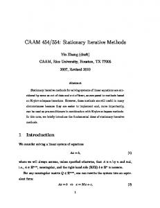
tear-off theory, the sharp-distillation product points must belong to the areas of possible product compositions. These areas can be bounded by scanning the phase-equilibrium coefficients on the edges of the concentration simplex [14, 15]. After choosing a feasible separation, one proceeds to designing a minimumreflux process (second step of the design procedure) by varying the reflux ratio and finding the points that lie on the reversible-distillation trajectories of the column sections. In this step, the minimum reflux ratio can be estimated with the use of the smallest angle criterion [16]. We will consider the most general intermediate separations such as 1, 2, …, l : h, …, n (the components of the overhead product are placed before the colon; the components of the bottom product, after the colon) and separations with distributed components: 1, 2, …, l, l + 1, …, h – 1, h : l, l + 1, …, h – 1, h, …, n. Here, components l and h are called the key components and components l + 1 through h – 1 are the distributed components. Four-component mixtures deserve special attention for the following reasons: the trajectory joining conditions allow convenient visualization; the algorithm of minimum-reflux calculation for these mixtures can be simplified relative to those for mixtures of five or more components. Since the minimum-reflux calculations for the direct (1 : 2, …, n) and indirect (1, 2, …, n – 1 : n) separations are much simpler [9], these separations are not considered here. To illustrate the minimum-reflux calculation for a four-component mixture, let us consider the intermediate separation 1, 2, (3) : (2), 3, 4 (Fig. 1). Hereafter, the impurity component is put in parentheses. In the minimum-reflux mode, the impurity component can be only the component that is most similar in volatility to the desired product components. In the case of sharp separation, the overhead product point D lies on edge 12 and the bottom product point W lies on edge 34 of the concentration tetrahedron. According to the trajectory tearoff theory, the separation in question is feasible if the tear-off conditions are satisfied at the tear-off points of 1 2 the sectional trajectories ( S r on edge 12, S r on face 1 2 123, S s on edge 34, and S s on face 234). For example, at some R, the following conditions must be satisfied at 1 the point S r corresponding to this R: L/V > K3, L/V > K4, 2 K1 > K3, K1 > K4, K2 > K3, and K2 > K4. At the point S r , the following conditions must be met: L/V > K4, K1 > K4, K2 > K4, and K3 > K4. In the case of real, quasi-sharp separation, there exist small regions (blackened in Fig. 1) attached to the points D and W inside the concentration tetrahedron which are formed by the product points at a preset quality of separation. The reversible-distillation trajectories for the points D and W are situated on
THEORETICAL FOUNDATIONS OF CHEMICAL ENGINEERING
Vol. 35
No. 3
2001
226
PETLYUK, DANILOV
faces 123 and 234, respectively (components 2 and 3 are the impurity components in the bottom and overhead products, respectively, in an infinite column). The following pairs of points in these trajectories correspond to various values of R (R1 < R2 < R3 < R4 < R5): 2 2 2 2 2 2 2 2 2 2 ( S r1, S s1, S r2 , S s2 , S r3, S s3, S r4 , S s4 ), and ( S r5 , S s5). Figure 2 plots the concentrations of components 1–3 at the 2 point S r in the top-section reversible-distillation trajectory as a function of R. According to the approximate method suggested by Koehler et al. [16], the smallest 2 2 angle between the xF S r and xF S s vectors corresponds to the minimum reflux ratio (see Fig. 1).
2 R5 R4
S2s
R3 R2
D
R1 ϕ
R1
xF
R2 1
4 R3 R4
S2r W
R5
3 Fig. 1. Sectional reversible-distillation trajectories (dashed lines) for the intermediate separation 1, 2, (3) : (2), 3, 4 of a four-component mixture. The composition regions near D and W that meet the requirements imposed on the product 2 quality are blackened. ϕ is the angle between the xF S r and 2
xF S s vectors at the reflux ratio R3.
xi
1
xD1
2
2
Figure 3 plots the angle between the xF S r and xF S s vectors against R (the points R1–R5 are shown). The smallest angle between these vectors corresponds to some R3 ≈ Rmin. At this reflux ratio in the infinite column sections, the sectional distillation trajectories tear 2 2 off faces 123 and 234 at the points S r3 and S s3 to join inside the concentration tetrahedron. Figure 4 illustrates trajectory joining at minimum reflux. The portions of sectional trajectories that are inside the concentration tetrahedron can be calculated by the “piecewise nodal” method described elsewhere [13]. These trajec2 + tory portions are situated on the separatrices S r N r and 2 + S s N s of the trajectory bundles. The calculation is performed by the tray-by-tray technique, starting at an 2 inside point in the vicinity of S r for the top section and 2 in the vicinity of S s for the bottom section and proceed+ + ing to the corresponding nodes N r and N s . 2
xD2 xD3 0
R1
R2
R3
R4
R5
R
Fig. 2. Concentration of the ith component (i = 1, 2, 3) on the top-section reversible-distillation trajectory as a function of R.
ϕ
R1
R2
R3
R4 2
R5 2
R
Fig. 3. Angle ϕ between the xF S r and xF S s vectors as a function of R.
+
Let xr and xs be some points of the separatrices S r N r 2 + and S s N s , respectively. The following conditions must be satisfied at the joining point of the minimum-reflux trajectories: (1) the angle between the xFxr and xFxs vectors must be zero (Fig. 5), because xr is equal to the composition on the tray above the feed cross section (xf – 1), xs is equal to the composition on the tray below the feed cross section (xf), and, as follows from the material-balance condition for the feed cross section, the points xF , xf – 1, and xf must lie on one straight line; (2) as follows from the same condition, the distances separating these three points must obey the lever rule. If the second condition is not satisfied with a sufficient accuracy, the estimated Rmin value must be corrected in an appropriate way. Checking trajectory joining is performed simulta2 + neously with calculating the trajectory portions S r N r 2 + and S s N s ; that is, these portions are refined until the minimum angle between the xFxr and xFxs vectors is attained. In the general case, the joining points in the sectional trajectories correspond to fractional numbers of trays in both sections. These numbers can be derived by linear interpolation between the compositions on
THEORETICAL FOUNDATIONS OF CHEMICAL ENGINEERING
Vol. 35
No. 3
2001
FEW-STEP ITERATIVE METHODS FOR DISTILLATION PROCESS DESIGN
two adjacent trays in the vicinity of the points xf – 1 and xf . Figure 6 shows how the angle ϕ between the xFxr and xFxs vectors varies with the concentration of component 4 in the tray-by-tray calculation of the trajectory por2 + 2 + tions S r N r and S s N s for infinite sections. Since in the design procedure Rmin is the lower limit of reflux ratios that ensure the desired product quality in a finite column, it is unnecessary to calculate Rmin with a high accuracy. Therefore, the Rmin refinement step can be skipped in many cases. The present algorithm is also valid for the case of the so-called tangential pinch [16], in which the functions R or S pass through an extremum in going along the sectional reversible-distillation trajectories. There are some peculiarities in the minimum-reflux calculation for those separations of azeotropic mixtures which are possible only if heat is supplied to or removed from the feed tray [12]. As mentioned above, this situation may take place if the sectional trajectory can tear off the boundary element of the concentration simplex only in a limited range of reflux or reboil ratios t (i.e., there exists a maximum tear-off reflux ratio R max
2
2
2
2
2
(a)
S1r S2s
D N+r ∞ xf–1
xF
x∞ f 1
4
S2r N+s
W S1s 3 (b)
t
or a maximum tear-off reboil ratio S max ). If in this case the minimum reflux or reboil ratio necessary for traject t tory joining is higher than R max or S max , the chosen separation is feasible only if heat is supplied to or withdrawn from the feed tray. Strictly speaking, heat can be transferred to or from some intermediate tray, but, for convenient analysis, we will consider heat transfer at the feed tray. If the situation described above does take place, the minimum-reflux calculation is carried out as follows. At every calculated point of the sectional reversibledistillation trajectory, one checks whether the tear-off condition is satisfied. For the separation 1, 2, (3) : (2), 3, 4, satisfaction of the L/V > K4 condition (component 4 is missing from face 123) is checked at every point of 2 the top-section reversible-distillation trajectory ( S r1 ,
227
S2s ∞
xf
xF
+
Nr ∞ xf–1
S2r
N+s
Fig. 4. (a) Joining of the sectional trajectories (thick lines with arrows) at minimum reflux. (b) Intersection of the tri2
+
2
+
2
+
2
angles xF S r N r and xF S s N s . The points S r , N r , S s , and +
N s lie on faces 123, 124, 234, and 134, respectively. 䊉 is a stable node, 䊊 is an unstable node, ⊕ is a saddle, the thin solid lines are the material-balance lines, and the other lines and points are the same as in Fig. 1.
S r2 , S r3 , S r4 , S r5 , and so on). The point at which this t
condition ceases to be satisfied corresponds to R max. If t at R < R max the joining conditions are not satisfied, then, to make the desired separation possible, it is necessary to withdraw heat from the feed tray. If the same situation obtains in the bottom section, heat must be supplied to the feed tray. Further, the minimum-reflux process conditions are determined at a fixed R close to t 2 R max and at a varied S. A fixed point S r, fix in the top-section reversible-distillation trajectory corresponds to the fixed R. Therefore, the smallest angle criterion must be modified in this case: at a varied reboil ratio, the small2 2 est angle between the xF S r, fix and xF S s vectors has to be determined.
For mixtures containing five or more components, 2 + 2 + the separatrix trajectory bundles S r N r and S s N s , which are the boundary trajectories of the sectional trajectory bundles at fixed reflux and reboil ratios, are multidi2
+
mensional. The separatrix trajectory bundle S r N r con2
+
tains, besides the stationary points S r and N r , the stationary points belonging to all hyperfaces of the concentration simplex that are adjacent to the hyperface containing the overhead-product point and have a dimensionality higher by unity. For example, if in a five-component system (K1 > K2 > K3 > K4 > K5) the
THEORETICAL FOUNDATIONS OF CHEMICAL ENGINEERING
Vol. 35
No. 3
2001
228
PETLYUK, DANILOV
The dimensionality of these bundles is equal to the number of components that are missing from the mix2 2 ture represented by the points S r and S s . At minimum reflux, the composition points for the trays that are above and below the feed cross section, xf – 1 and xf, must lie on one straight line with the liquid feed composition point xF and in the boundary elements of the
2
S1r
❚
❚ ❚ ❚
S2s ❚
2
❚ ❚ ❚
xs
2
❚
D
❚
❚
❚
❚
ϕ
xF
❚❚
❚
❚
❚
1 N+s
❚
❚❚
❚
S2r
❚
❚
❚
❚
❚
❚
❚ ❚❚
+
+
2
+
hypersurface xF S s N s , whose vertex is the point xF and 4
xr W
2
2
2
Fig. 5. Angle ϕ between the xFxr and xFxs vectors in the 2
+
whose generator is the separatrix bundle S s N s . Likewise, the point xf must lie at the intersection of the sep+
aratrix bundle S s N s with the conical surface or hyper-
3 +
tray-by-tray calculation of the trajectory portions S r N r and +
S s N s for infinite column sections. The tray compositions are shown in the sectional trajectories. The other lines and points are the same as in Fig. 4.
+
surface xF S r N r . The material-balance line in the feed cross section, xf – 1xf xF, is the common generator for two conical surfaces or hypersurfaces. Although the separatrix bundles are multidimensional, the intersection of 2 + 2 + the bundle S r N r with the manifold xF S s N s is zerodimensional; that is, it is a point in the multidimensional concentration simplex considered. The intersec2 + tion of the separatrix bundle S s N s with the manifold 2
+
xF S r N r is also a point. As is demonstrated above, xf – 1 and xf for a quaternary mixture can be determined by
ϕ
2
xs4
2
x ∞f, 4
0
x f ∞– 1, 4
x4
Fig. 6. Angle ϕ between the xFxr and xFxs vectors as a function of x4 in the tray-by-tray calculation of the trajectory 2
+
+
2
+
calculating the trajectories S r N r and S s N s by the “piecewise nodal” method. However, when the bundles 2 + 2 + S r N r and S s N s are not one-dimensional, this method is inefficient. Therefore, xf – 1 and xf for a mixture of five or more components should be determined by lineariz2 + 2 + ing the separatrix bundles S r N r and S s N s and the
xr4
2
+
portions S r N r and S s N s for infinite column sections.
overhead-product point lies on edge 12, then the point 2
2
separatrix bundle S r N r with the conical surface or
N+r
S1s
2
+
sectional trajectory bundles S r N r and S s N s . Therefore, the point xf – 1 must lie at the intersection of the
+
S r belongs to face 123, the point N r belongs to face 2
+
125, and the other saddle point of the S r N r bundle 2 + belongs to face 124; that is, the S r N r bundle is two2 + dimensional. The stationary points of the S s N s bundle are arranged in a similar fashion.
+
2
+
xF S r N r and xF S s N s manifolds (i.e., by passing from the surfaces and hypersurfaces to planes and hyperplanes). The separatrix trajectory bundles are best linearized in terms of the eigenvectors of the set of distillation 2 2 equations for the point S r or S s . These eigenvectors depend on the phase-equilibrium coefficients of the components that are missing from the mixture at these points. The intersection points of the thus-linearized lin lin bundles with the manifolds x f – 1 and x f are determined by solving a set of linear equations. The positions of the points xf – 1 and xf can be refined by moving lin lin
these points along the straight line xF x f x f – 1 and performing trial tray-by-tray minimum-reflux calculations for the sections, starting at the chosen points xf – 1 and xf and proceeding to the column ends. The point xf – 1 must
THEORETICAL FOUNDATIONS OF CHEMICAL ENGINEERING
Vol. 35
No. 3
2001
FEW-STEP ITERATIVE METHODS FOR DISTILLATION PROCESS DESIGN
be located at the boundary of the domain of attraction – of the node N r ; the point xf, at the boundary of the
229
2
–
domain of attraction of the node N s . Provided that the points xF , xf – 1, and xf obey the lever rule, this method is a rigorous method for determining Rmin, xf – 1, and xf . Additional difficulties arise when some of the components are distributed between the products. In this case, the number of components missing from the mix2 2 ture at the points S r and S s and, correspondingly, the dimensionality of the separatrix trajectory bundles 2 + 2 + S r N r and S s N s are lower than in the absence of distributed components. The minimum-reflux calculation for a separation with distributed components involves seeking the product compositions for which the above-mentioned sets of linear equations are consistent at minimum reflux. The variables in this calculation are the distribution dist dist coefficients d i / w i of all the distributed components. As an example, let us consider the simplest separation for a four-component mixture (K1 > K2 > K3 > K4), viz., the separation 1, 2 : 2, 3, 4 with one distributed component (Fig. 7). In this instance, the potential product points satisfying the material-balance conditions fill the segment D1D2 on edge 12 and the segment W1W2 in face 234. These segments contain the points Dopt and Wopt, which correspond to the optimal distribution of component 2 between the products. For an arbitrary point in the segment D1D2 and the corresponding point in the segment W1W2, we can find Rmin by calculating, as described above, the portions of the reversible distillation trajectories in faces 123 and 234 and mini2 2 mizing the angle between the xF S r and xF S s vectors. At the points Dopt and Wopt, Rmin takes its minimum value (minRmin). At this R value, each column section has two constant-concentration zones for sharp separation and a single one if the products contain impurity components. In the former case, these zones are represented 1 2 by the stationary points S r and S r for the top section +
and the stationary points Ss and N s for the bottom sec+
2
+
tion (the point N s belongs to the triangle xF S r N r ); in 2
the latter case, the stationary points are S r for the top +
section and N s for the bottom section. The minimumreflux calculation involves determining the mixture compositions at Dopt and Wopt and the min Rmin value. The algorithm for solving this problem consists in estimating these parameters using a set of the Underwood equations (under the assumption that the mixture to be separated is ideal) and in refining the resulting esti-
Ss
S1r
D2
W1
Dopt
D1 1
F
N+r Wopt
xf – 1
S2r
4
xf ≡ N+r W2
3 Fig. 7. Joining of the sectional minimum-reflux trajectories for the 1, 2 : 2, 3, 4 separation of a four-component mixture (K1 > K2 > K3 > K4). The feed is liquid. D1D2 and W1W2 are, respectively, the segments of potential overhead- and bottomproduct compositions that satisfy the material-balance condition. The other lines and points are the same as in Fig. 4.
mates. Refining the composition at the point D at a fixed R is alternated with refining R at a fixed point D. In the design of distillation with many distributed components, as in the important case of oil refining, the rigorous minimum-reflux calculation is carried out in a similar way. Refining the liquid composition at one of the product points (e.g., the point D) is performed by using the steepest descent method for the criterion minRmin. Few-Step Iterative Design Procedure The calculation steps described above provide Rmin and Smin values and the xir(R), xis(R), Tr(R), and Ts(R) values for the sectional reversible-distillation trajectories. These data are sufficient for the design and optimal design of real, finite columns, including those with heat supply or removal at some intermediate trays of the sections. For correct understanding of the new calculation method, which is based on the theory of joining of the sectional distillation trajectories, it is necessary to analyze the mutual arrangement of the trajectories in finite and infinite columns at a fixed reflux ratio and the location of the material-balance line in the feed cross section (the line joining the liquid-feed composition point xF and
THEORETICAL FOUNDATIONS OF CHEMICAL ENGINEERING
Vol. 35
No. 3
2001
230
PETLYUK, DANILOV 2
2
(a)
(b) S1r
S1r
S2s
x ft – 1
D
S2s
D
xf∞
xF
xF
xfl
S2r
N+r
1
S2r
N+r
4 1
4
N+s
N+s
W
W S1s
S1s
3
3 2
(c)
x ft – 1
(d) S1r
x∞f
S2s xf
D
xf
xf – 1
xF x fl
xF
x f∞– 1
S2r
N+r
xf – 1
1
4
N+s W 3
S1s ∞
∞
Fig. 8. Sectional distillation trajectories at R > Rmin: (a) xf = x f ; (b) xf – 1 = x f – 1; (c) the point xf is in the interior of the segment of possible compositions; (d) the segments of possible compositions on the trays above and below the feed cross section (enlarged fragment of (a–c)). The line and point designations are the same as in Fig. 4.
the point representing the liquid composition on the trays above and below the feed cross section, xf – 1 and xf). At a given product composition and reflux (reboil) ratio, the liquid compositions on the trays of a section are described by the same set of equations for finite and infinite columns; therefore, both the finite- and infinitecolumn trajectories belong to the same bundle, but the former can contain no stationary or pseudostationary (tear-off) points. Since the finite- and infinite-column trajectories belong to the same bundle, it is possible to work out a
general procedure for their calculation and, on the basis of the trajectory joining theory, develop a method for determining possible liquid compositions on the trays above and below the feed cross section. Next, it is possible to elaborate few-step iterative methods for column design. 1 2
+
1 2
+
Figure 8 shows the planes S r S r N r and S s S s N s which bound the sectional trajectory bundles at some R > Rmin for the intermediate separation 1, 2 : 3, 4 of an ideal mixture. Also shown are the two limiting loca-
THEORETICAL FOUNDATIONS OF CHEMICAL ENGINEERING
Vol. 35
No. 3
2001
FEW-STEP ITERATIVE METHODS FOR DISTILLATION PROCESS DESIGN
tions of the material-balance line in the feed cross secl ∞ ∞ t tion, xF x f x f – 1 and xFx f x f – 1. The limiting liquid coml ∞ positions are x f and x f on the tray below the feed cross t ∞ section and x f – 1 and x f – 1 on the tray above the feed cross section; that is, there are segments of possible liquid compositions for the trays above and below the feed cross section. According to the lever rule, the ratio of the segment [xf , xF ] to the segment [xf – 1, xf ] is equal to the ratio of Lr to LF (the flow rate of the liquid part of the feed) and is constant at some R. For one of the limiting locations of the material-balance line, the point t 2 + x f – 1 lies on the intersection line of the planes xF S s N s 1 2
231
nr + ns σ1 σ2 σ3 σ4
xf
xf, opt
+
and S r S r N r (Fig. 8a). In this case, the bottom section of the column is infinite, part of its trajectory belongs to t 2 + the separatrix S s N s , and the point x f – 1 is the limit of possible compositions xf – 1 that is the farthest from the 2
Fig. 9. The total number of trays (nr + ns) as a function of the concentration of one of the components at the point xf for various values of σ = R/Rmin (σ1 < σ2 < σ3 < σ4) (xf, opt is the optimal location of the feed tray).
+
separatrix S r N r . The top-section trajectory is most dis2
tant from the stationary point S r , and the number of trays in the top section, nr, is the smallest. For the com∞
t
positions x f and x f – 1 considered, the feed cross section is situated at the maximum height. For the feed cross section situated at the minimum height (the other limiting location of the material-ball ance line), the point x f lies on the intersection line of 2
+
1 2
+
the planes xF S r N r and S s S s N s (Fig. 8b). In this case, the top section is infinite, part of its trajectory belongs 2 + l to the separatrix S r N r , and the point x f is the limit of possible compositions xf that is the farthest from the 2
+
separatrix S s N s . The bottom-section trajectory is most 2
distant from the stationary point S s , and the number of trays in the bottom section, ns, is the smallest. For some intermediate positions of the points xf and xf – 1, the total number of trays in the column, nr + ns, takes the minimum value at specified impurity concentrations in the products and an R > Rmin (Fig. 8c). Note that, at R = Rmin, both nr and ns are infinitely large and the segments of possible xf and xf – 1 have a zero length. As σ = R/Rmin is raised, these segments grow in length. Therefore, if the points xf and xf – 1 are in the interior of the respective segments, their distances from the sepa2 + 2 + ratrix lines S r N r and S s N s (which bound the sectional trajectory bundles) grow with rising σ; as a consequence, the total number of trays decreases, because the sectional trajectories recede from the stationary points. Figure 9 plots the total number of trays as a function of σ and the concentration of one of the components at the point xf .
Now we can turn to the few-step iterative algorithm for design calculation at a given σ. The end points of the segments of possible compositions, xf and xf – 1, are found on the separatrix lines from the material-balance condition. An arbitrary point xf is selected inside the segment l
∞
[ x f , x f ], and the corresponding point xf – 1 is located by using the material-balance equation for the feed cross section. Next, the designer performs the design calculation, starting at the feed cross section and going tray-by-tray to the column ends until the desired quality of the products is attained. This calculation is quite stable, because the points xf – 1 and xf are situated inside the sectional trajectory bundles for the preset R and the – – nodal points N r and N s lie near the extensions of edges 12 and 34 (Fig. 10). The sharper the separation (the lower the admissible concentrations of components 3 and 4 in the overhead product and components 1 and 2 in the bottoms), the more exactly the materialbalance condition is satisfied after the calculation is complete. For fairly sharp separations, the suggested method of design calculation is noniterative. For the sharp direct and indirect separations 1 : 2, 3, 4 and 1, 2, 3 : 4, the “unidirectional” (upward and downward, respectively) tray-by-tray calculation for the column as a whole is also noniterative [17]. The suggested method is applicable to any separation of a multicomponent mixture. If the separation is not very sharp (the products contain considerable amounts of impurity components), a few iterations are necessary, because the starting product points D and W cannot be located with a sufficient accuracy. After the first run from the feed section to the column ends, the calculated product compositions do
THEORETICAL FOUNDATIONS OF CHEMICAL ENGINEERING
Vol. 35
No. 3
2001
232
PETLYUK, DANILOV 2 S1r
S2s
D xf xF N–s
N+r
S2r
xf – 1
1
4
N+s W N–r
S1s 3
Fig. 10. Distillation trajectories for the intermediate separation 1, 2, (3) : (2), 3, 4 (K1 > K2 > K3 > K4) in a finite and an infinite section at R > Rmin. The line and point designations are the same as in Fig. 4.
not satisfy the component balance conditions with the required accuracy. In view of this, the product compositions must be corrected according to the results of the first run. This correction and the tray-by-tray run from the feed cross section to the column ends have to be performed several times until the component-balance condition is satisfied with the required accuracy. For nonideal and azeotropic mixtures, the separatrices 2 + 2 + 1 2 + S r N r , S s N s and the separatrix surfaces S r S r N r and 1 2
+
S s S s N s are curved. However, these distinctions imply virtually no changes in the described algorithm. Thus, for a four-component mixture, the noniterative distillation design calculation at a preset R is carried out in two basic half-steps: (1) calculating the distillation trajectory in infinite sections in the direction of ∞ ∞ the feed cross section to locate the points x f – 1 and x f and (2) calculating the distillation trajectory in finite sections in the column-end directions to determine the necessary number of trays in each section. For mixtures consisting of five or more components, ∞ the first half-step should be modified: the points x f – 1 ∞ and x f should be located by linearizing the separatrix 2 + 2 + 1 2 + 1 2 + bundles S r N r , S s N s , S r S r N r , and S s S s N s followed by solving the resulting set of linear equations (as in the minimum-reflux calculation) rather than by running a “piecewise nodal” calculation starting at the column ends and proceeding to the feed cross section. Linearization brings about some error, which can be eliminated by finding the intersection points of the separatrix
bundles. Figure 11 maps the two-dimensional separa2 + trix trajectory bundle S r N r in the top section and the 2
+
one dimensional separatrix S s N s of the bottom-section trajectory bundle for the separation 1, 2 : 3, 4, 5 of a fivecomponent mixture {K1 > K2 > K3 > K4 > K5). The points ∞
∞
x f – 1 and x f belong to the common generator of the 2
+
conical surface xF S s N s and the conical hypersurface 2 + xF S r N r . This algorithm provides rather accurate results even after the first run owing to the coincidence of the following favorable circumstances: (1) at the starting points xf – 1 and xf of the sectional trajectories, no trace components are present and, therefore, the concentrations of all components can be determined with a low relative error; (2) the points xf – 1 and xf are situated inside sectional trajectory bundles; (3) the product points are situated inside the sectional trajectory bundles, on the way from the initial points xf – 1 and xf of the – – calculated trajectories to the nodal points N r and N s ; and (4) the trajectories concentrate near the product points (i.e., these points lie near the boundary elements of the bundle). Optimal Design Procedure Optimal design of a simple distillation column means optimizing the separation pressure, reflux ratio, product rate, and the number of trays in each section. If the boiling temperature varies in a wide range, the
THEORETICAL FOUNDATIONS OF CHEMICAL ENGINEERING
Vol. 35
No. 3
2001
FEW-STEP ITERATIVE METHODS FOR DISTILLATION PROCESS DESIGN
energy consumed in separation can be reduced by supplying heat to or removing heat from some intermediate cross sections of the column. In this case, the extra optimization parameters are the heat-supply and/or heatremoval cross sections and rates. Some parameters (separation pressure and product rate in the case of sharp separation without component distribution) can be optimized independently of the others. This markedly simplifies the problem. Depending on the mixture, the optimal separation pressure is determined from various considerations, but, as a rule, the choice of pressure is governed by the boiling temperatures of the products and some other quantities that are independent of the design and operating parameters of the process. Therefore, in most cases, the separation pressure can be specified before performing design calculation. When there are no distributed components, the product rate can also be unambiguously determined without design calculations. In some separations with distributed components, it is necessary to optimize component distribution between the products. In brief, this problem is considered above for distillation at minimum reflux. In view of the above, the optimal design problem for a simple column without heat supply (removal) at some middle cross section reduces to optimizing σ and xf (xf – 1, ns, and nr depend on σ and xf). The optimal values of these parameters can be estimated without performing a series of calculations. For example, one can take σ = 1.2 and xf to be the midpoint of the seg∞ l ment [ x f , x f ]. A more rigorous approach implies a series of calculations for σ varied in a specified interval (e.g., 1.1–1.5) and xf varied in the vicinity of the mid∞ l point of the segment [ x f , x f ]σ. The optimum value of xf at a given σ ( x fσ ) implies the minimum total number of trays (ns + nr) (Fig. 8). The optimum value of σ implies the minimum cost of the process (in terms of column height, controllability of the process, and some other parameters). Optimization can be carried out without product-composition iterations, because small variations in the product compositions have almost no effect on the calculated total number of trays. If the boiling temperature of the mixture varies in a wide range and it is reasonable to use intermediate heat supply and/or removal, the optimal temperature levels and heat supply and/or removal rates have to be determined by the pinch method [18], which meshes perfectly with the suggested few-step iterative method of optimal design. While calculating the sectional reversible-distillas tion trajectories to determine Rmin, we derived T r (R) opt
s
and T s (R) functions to be used in the pinch method. Figure 12 shows the profiles of the liquid flow rate that
233
2
xF
Sr2
Ss2 x∞ f
Ns+
Nr+
1
5 Sr3
xf∞– 1
3
4
Fig. 11. The material-balance line xF xf – 1 in the feed cross ∞ ∞ xf –1
section xF x f
for the intermediate separation 1, 2 : 3, 2
3
4, 5 of a five-component mixture. The points S r , S r , and + N r lie in the two-dimensional faces 123, 124, and 125, 2
+
respectively; the points S s and N s , in the three-dimensional hyperfaces 2345 and 1234, respectively. The thick arrow-ended lines bound the separatrix trajectory bundles 2 3 + 2 + S r S r N r and S s N s . The thin solid lines are the generators 2 3
+
of the three-dimensional conical hypersurface xF S r S r N r . The dashed lines are the generators of the two-dimensional 2 + conical surface xF S s N s .
correspond to these functions for an infinite column 2 with reversible distillation between D and S r and 2
between W and S s and for an infinite column with a heat-supply point in the bottom section and another one in the top section (it is accepted that, in the heat-supply and heat-removal cross sections, the liquid and vapor are in equilibrium, giving rise to extra stationary points in in x con and x reb), which are shown in Fig. 13. The theoretical work of separation A in the column considered is A = L con /T con + ∆L con /T con – L reb /T reb – ∆L reb /T reb . (1) in
in
in
in
Compared to the adiabatic column, the column with intermediate heat supply and/or removal provides a separation work economy that is proportional to the area of the corresponding hatched rectangle in Fig. 12. s s The functions T r (R) and T s (R) enable one to determine the optimal temperatures at the heat-supply and
THEORETICAL FOUNDATIONS OF CHEMICAL ENGINEERING
Vol. 35
No. 3
2001
234
PETLYUK, DANILOV in
D
T –1
Qcon
in ) –1 (Tcon opt
in Qcon
Lad
Lrev
(Trt) –1
in
F (Tst) –1 in ) –1 (Treb opt
Lad
Lrev
in Qreb
Qreb
in Lrev
W L Fig. 12. Profiles of the liquid flow rate L on the column trays as a function of T –1 for adiabatic distillation (Lad), partially reversible distillation (Lrev), and distillation with intermediin
t
in
t
ate heat supply ( L reb) and/or removal ( L con ). T r and T s are the temperatures at the trajectory tear-off points in the infi2
2
nite top and bottom sections ( S r and S s , respectively). The hatched rectangles visualize the separation work economy provided by intermediate heat supply (removal).
2
S2s
S1r x∞f D
in xcon
xF 1
xf xf – 1
N+r 4
in xreb
N+s S2r
W
x f∞– 1
in
heat-removal points, ( T reb )opt and ( T con )opt, for which the areas of the hatched rectangles reach their maximum values. In practice, to optimize the heat-supply and heat-removal rates, the designer should use, instead of function (1), an economic criterion taking into account the cost of heat or the cooling agent, depending on the temperature levels.
in Lcon
S1s 3
Fig. 13. Distillation trajectories in infinite and finite sections with intermediate heat supply (removal). The line and point designations are the same as in Fig. 4.
in
The ( T reb)opt and ( T con )opt values and the correspondin in ing ∆ ∆L reb and ∆ ∆L con values are used in the tray-bytray calculation of distillation trajectories from the feed cross section to the column ends. As is seen from Fig. 12, the liquid flow rates in the middle part of the column considered are the same as in the adiabatic column. Therefore, for a column with intermediate heat supply or removal, a single modification must be made to the suggested algorithm: once the temperature level in in (T reb)opt or ( T con )opt has been reached in going from the feed cross section toward the column end, the liquid or in vapor flow rate must be changed stepwise by the ∆L reb in or ∆L con value. The distillation trajectories in an infinite and a finite section with intermediate heat supply or removal are shown in Fig. 13. Thus, our complex design algorithm consists of the following steps: (1) Specify the compositions of the products of sharp separation. (2) Check the feasibility of the desired separation for azeotropic mixtures. (3) Check the feasibility of the desired separation for azeotropic mixtures in the case of no heat supplied to (removed from) the middle part of the column. (4) Calculate the minimum reflux ratio. (5) Calculate the possible liquid compositions on the trays above and below the feed cross section at a given excess reflux factor. (6) Determine the necessary number of trays in the column sections at this excess reflux factor and specified liquid compositions on the trays above and below the feed cross section. (7) Determine the necessary number of trays for the optimum liquid compositions on the trays above and below the feed cross section. (8) Determine the necessary number of trays at the optimum excess reflux factor. (9) For a column with intermediate heat supply or removal, determine the temperature levels and heat supply (removal) rate. The complex design calculation can be accomplished automatically, without interference from the designer. Although the volume of computation depends on the mixture to be separated and on the desired separation, the algorithm guarantees the optimal design.
THEORETICAL FOUNDATIONS OF CHEMICAL ENGINEERING
Vol. 35
No. 3
2001
FEW-STEP ITERATIVE METHODS FOR DISTILLATION PROCESS DESIGN
The algorithm is highly reliable, because all of its steps require few, if any, iterations. The elements of the optimal design method for a simple column that involve few iterations are applicable to any complex column and distillation complex.
235
– —unstable node; + —stable node; ∞—column section with an infinite number of trays. REFERENCES
NOTATION D—overhead product; d—amount of a component in the overhead product; F—feed flow rate; K—phase equilibrium coefficient; L—liquid flow rate in the column; Nr, Ns—stable nodes of the top- and bottom-section trajectory bundles, respectively; nr, ns—numbers of trays in the top and bottom sections, respectively; Q—supplied (removed) heat; R—reflux ratio; S—reboil ratio; Sr, Ss—saddles of the top- and bottom-section trajectory bundles, respectively; T—temperature; V—vapor flow rate in the column; W—bottom product; w—amount of a component in the bottom product; x—tray composition; σ—excess reflux factor. SUBSCRIPTS AND SUPERSCRIPTS ad—adiabatic; con—condenser; D—overhead product; dist—distributed components; f—feed tray; h—heavy key component; i = 1, ..., n, j = 1, ..., n—component nos.; in—intermediate; l—lowermost feed cross section (light key component); min—minimum value; opt—optimum value; r—top section of the column; reb—reboiler; rev—reversible distillation; s—bottom section of the column; t—tear-off point (the uppermost feed cross section); W—bottom product;
1. Lewis, W. and Matheson, G., Studies in Distillation Design of Rectifying Columns for Natural and Refinery Gasoline, Ind. Eng. Chem., 1932, vol. 24, no. 5, p. 494. 2. Thiele, E. and Geddes, R., Computation of Distillation Apparatus for Hydrocarbon Mixtures, Ind. Eng. Chem., 1933, vol. 25, no. 3, p. 289. 3. Russel, R.A., A Flexible and Reliable Method Solves Single-Tower and Crude-Distillation Column Problems, Chem. Eng., 1983, vol. 90, p. 53. 4. Viswanathan, J. and Grossmann, I.E., Optimal Feed Locations and Number of Trays for Distillation Columns with Multiple Feeds, Ind. Eng. Chem. Res., 1993, vol. 32, p. 2942. 5. Zharov, V.T. and Serafimov, L.A., Fiziko-khimicheskie osnovy distillyatsii i rektifikatsii (Physicochemical Foundations of Distillation and Rectification), Leningrad: Khimiya, 1975. 6. Petlyuk, F.B. and Serafimov, L.A., Mnogokomponentnaya rektifikatsiya. Teoriya i raschet (Multicomponent Distillation: Theory and Calculations), Moscow: Khimiya, 1983. 7. Serafimov, L.A., Timofeev, V.S., and Balashov, M.I., Rectification of Multicomponent Mixtures: III. Local Characteristics of the Trajectories of Continuous Rectification Process at Finite Reflux Ratios, Acta Chim. Hung., 1973, vol. 75, no. 3, p. 235. 8. Serafimov, L.A., Timofeev, V.S., and Balashov, M.I., Rectification of Multicomponent Mixtures: IV. NonLocal Characteristics of Continuous Rectification Trajectories for Ternary Mixtures at Finite Reflux Ratios, Acta Chim. Hung., 1973, vol. 75, no. 3, p. 255. 9. Julka, V. and Doherty, M.F., Geometric Behavior and Minimum Flows for Nonideal Multicomponent Distillation, Chem. Eng. Sci., 1990, vol. 45, no. 7, p. 1801. 10. Petlyuk, F.B., Vinogradova, E.I., and Serafimov, L.A., Feasible Compositions of the Products of Ternary Azeotropic Distillation at Minimum Reflux, Teor. Osn. Khim. Tekhnol., 1984, vol. 18, no. 2, p. 147. 11. Petlyuk, F.B., Simple Methods for Predicting Feasible Sharp Separations of Azeotropic Mixtures, Teor. Osn. Khim. Tekhnol., 1998, vol. 32, no. 3, p. 279. 12. Petlyuk, F.B. and Danilov, R.Yu., Calculation of Distillation Trajectories at Minimum Reflux for Ternary Azeotropic Mixtures, Teor. Osn. Khim. Tekhnol., 1998, vol. 32, no. 6, p. 604. 13. Petlyuk, F.B. and Danilov, R.Yu., Feasible Separation Variants and Minimum-Reflux Calculations for Multicomponent Azeotropic Mixtures, Teor. Osn. Khim. Tekhnol., 1999, vol. 33, no. 6, p. 629.
THEORETICAL FOUNDATIONS OF CHEMICAL ENGINEERING
Vol. 35
No. 3
2001
236
PETLYUK, DANILOV
14. Petlyuk, F.B. and Danilov, R.Yu., Synthesis of Separation Flowsheets for Multicomponent Azeotropic Mixtures on the Basis of the Distillation Theory. Presynthesis: Prediction of Feasible Product Compositions, Teor. Osn. Khim. Tekhnol., 2000, vol. 34, no. 3, p. 265. 15. Petlyuk, F.B. and Danilov, R.Yu., Synthesis of Separation Flowsheets for Multicomponent Azeotropic Mixtures on the Basis of the Distillation Theory. Synthesis: Finding Optimal Separation Flowsheets, Teor. Osn. Khim. Tekhnol., 2000, vol. 34, no. 5, p. 494.
16. Koehler, J., Aguirre, P., and Blass, E., Minimum Reflux Calculations for Nonideal Mixtures Using the Reversible Distillation Model, Chem. Eng. Sci., 1991, vol. 46, p. 3007. 17. Platonov, V.M. and Bergo, B.G., Razdelenie mnogokomponentnykh smesei (Separation of Multicomponent Mixtures), Moscow: Khimiya, 1965, p. 48. 18. Dhole, V.R. and Linnhoff, B., Distillation Column Targets, Comput. Chem. Eng., 1993, vol. 17, no. 5/6, p. 549.
THEORETICAL FOUNDATIONS OF CHEMICAL ENGINEERING
Vol. 35
No. 3
2001