403
Field and laboratory performance of bridge columns repaired with wrapped glass-fibrereinforced-polymer sheets1 Shamim A. Sheikh
Abstract: Several bridge columns, in which concrete was delaminated as a result of steel corrosion, were repaired in the mid 1990s. Different types of grout, including one based on expansive cement, were used to rebuild the damaged columns to their original shape; the columns were then wrapped with glass-fibre-reinforced polymers (GFRPs). The associated lab study indicated that the observed damage caused a reduction of about 20% in the axial-load-carrying capacity of the columns and much larger reductions in ductility and energy-dissipating capacity. The experimental results also showed that the strength and ductility of the columns could be recovered by repairing them with GFRP. Long-term monitoring of three columns repaired in the field using GFRP has indicated their excellent performance. No deterioration has been observed in the fibre-reinforced polymer or in the columns in more than 10 years. Monitoring has also shown a reduction in the rate and associated risk of corrosion over time; thus, this is a more durable retrofitting technique than traditional ones, such as steel jacketing. Key words: concrete, columns, corrosion, cyclic loading, ductility, expansive cement, glass-fibre-reinforced polymers, monitoring, repair, strength. Résumé : De nombreux piliers de ponts dans lesquels le béton était désagrégé à la suite de la corrosion de l’acier ont été réparés dans le milieu des années 1990. Plusieurs types de coulis, dont un à base de ciment expansif, ont été utilisés pour rebâtir les piliers endommagés à leur forme originale avant de les envelopper de polymères renforcés de fibres de verre (« GFRP »). L’étude connexe en laboratoire a montré que les dommages observés réduisaient la capacité portante axiale des piliers de 20 % et causaient des réductions beaucoup plus importantes en ductilité et dans la capacité de dissiper l’énergie. Les résultats de l’expérience ont également montré que la résistance et la ductilité des piliers pourraient être récupérées en les réparant avec des « GFRP ». Le suivi à long terme de trois piliers réparés sur le terrain en utilisant des « GFRP » a montré leur excellent comportement. Aucune détérioration n’a été observée dans les polymères renforcés de fibres ou les piliers en plus de 10 ans. Le suivi a également montré une réduction dans le temps du taux et du risque associé de corrosion, fournissant ainsi une méthode de modification plus durable que les méthodes conventionnelles telles que les enveloppes en acier. Mots-clés : béton, piliers, corrosion, charges cycliques, ductilité, ciment expansif, polymères renforcés de fibres de verre, suivi, réparation, résistance. [Traduit par la Rédaction]
Sheikh
413
Introduction There is a vast inventory of damaged concrete structures around the world that are either unsafe to use or are in dire need of repair to remain in use. The damage may be caused by extreme environmental conditions, overload, or routine aging. The extreme environmental conditions include expoReceived 25 November 2005. Revision accepted 24 July 2006. Published on the NRC Research Press Web site at cjce.nrc.ca on 2 May 2007. S.A. Sheikh. Department of Civil Engineering, University of Toronto, 35 St. George Street, Toronto, ON M5S 1A4, Canada (e-mail:
[email protected]). Written discussion of this article is welcomed and will be received by the Editor until 31 July 2007. 1
This article is one of a selection of papers in this Special Issue on Intelligent Sensing for Innovative Structures (ISIS Canada).
Can. J. Civ. Eng. 34: 403–413 (2007)
sure to sulfates, acids, alkalis, etc., variations in temperature during freezing and thawing conditions, and changes in moisture content. These factors affect the durability of cement paste and aggregate in concrete. In areas where deicing salt is used on roads, chloride ion ingress is one of the main reasons for the corrosion of steel in reinforced concrete structures. In addition, design inadequacies, unsound construction practices, and a lack of quality control, combined with minimal maintenance, have been responsible for a lot of structural damage. During the last 10 years, several concrete structures in and around Toronto have been repaired or strengthened with surface-bonded fibre-reinforced-polymer (FRP) sheets and monitored for performance (Sheikh and Homam 2004). These structures include, among others, a concrete platform in an oil refinery, bridge columns and culverts along major highways, and high-rise apartment and condominium buildings. The repaired components include slabs, beams, walls, and columns. This paper concentrates on research involving a bridge with its columns damaged primarily by chlorides from de-
doi:10.1139/L06-112
© 2007 NRC Canada
404
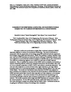
icing salt. The bridge is in Toronto, on Highway 401, and was built in the 1960s, using concrete with a specified strength of 20.7 MPa. The highway has seven westbound and six eastbound lanes at this location. Figure 1 shows several damaged columns on the westbound part of the bridge. The columns are 920–1010 mm in diameter. The damage seen in Fig. 1 is concentrated at the bents that are directly below the expansion joints. Over time, the joint sealant and other materials deteriorated as a result of extreme weather conditions and chemicals from de-icing salts, allowing the water–ice–salt solution to pass through the joints to the reinforced concrete bents. Accumulation of this solution at the bent top and its continuous flow downward resulted in deterioration of the concrete, as well as in corrosion of the steel. The columns may also have been subjected to splashes of salt solution from cars using the area under the bridge as a parking lot. In addition to the direct chemical attack, the structure was subjected to the usual environmental effects of freeze–thaw cycles, ultraviolet exposure, water, wet–dry cycles, etc. As a result, the spiral steel in the columns and the tie steel in the beams were severely corroded, which led to severe delamination of the cover concrete in both the columns and the girders. However, little corrosion was observed in the longitudinal bars.
Repair of columns Conventional repair techniques have been successfully employed for decades, but in most cases they are cumbersome and require closing of the entire facility during repair. In addition, the need to repeat repairs at the same location within a few years is quite common. Repair techniques that allow regular activities to continue with minimal disruption and provide a durable solution (not requiring repeated repairs) present an attractive and much-needed alternative to traditional procedures. In the mid-1990s, glass-fibrereinforced polymers (GFRPs) were selected for the repair of the damaged bridge columns. In addition to being less labour- and equipment-intensive than traditional repair materials, FRPs are lighter, stronger, and resistant to electrochemical corrosion. Two commercially available grouts and another grout, which was based on a specially developed expansive cement, were used to rebuild the columns back to their original shape. Brief details of the two nontraditional materials, the expansive cement and the GFRP, are provided in the following sections. Expansive cement A cement with large expansion potential was developed by Timusk and Sheikh (1977). Although this cement had the required degree of expansion for this application, it displayed rapid-set properties, making its use in large volumes unfeasible. Further studies resulted in a new cement formulation that overcame this deficiency (Sheikh et al. 1994). The new formulation is a mixture of normal Portland cement and an expansive component. This expansive component consists of 62.5% hydrated high-alumina cement (H-HAC), 30% moulding plaster, and 7.5% hydrated lime. The proportions of normal Portland cement and expansive component used can be varied depending on the amount of expansion required. For the column repair in this study, the expansive
Can. J. Civ. Eng. Vol. 34, 2007
cement contained 60% normal Portland cement and 40% expansive component. All the components of the expansive cement are commercially available except H-HAC. This component was obtained by mixing water and a high-alumina cement (HAC) in a ratio of 0.5. The resulting paste was then cast in a 75– 100 mm thick slab. After hydration for 24 h, the slab was crushed and dried in an oven for 24 h and then ground into a fine powder with particle sizes ranging from 75 to 150 µm. Using H-HAC in place of HAC in the formulation of expansive cement improved the set properties to the desired levels: expansive cement with HAC does not provide enough time before setting for most uses in the field, whereas expansive cement with H-HAC displayed early age behaviour that was suitable for field applications. Figure 2 compares various properties of two expansive concrete samples, E6 and E11 (Sheikh et al. 1994). The only difference between the two samples is that E6 contained HAC and E11 contained H-HAC. The mix proportions are given in Table 1. A small amount of superplasticizer was used in the concrete to improve its workability considerably without adversely affecting the expansion properties. An initial slump of approximately 160 mm was maintained for about 30 min in E11, and at 60 min the slump was still approximately 100 mm. The concrete strength (Fig. 2a) was measured from tests on unconfined 100 mm × 200 mm cylindrical specimens that were cast in steel tubes with 6 mm wall thickness. The specimens in the steel tubes were cured in water under triaxially restrained conditions: the lateral restraint was provided by the tube wall, and the longitudinal restraint was provided by steel plates at the ends, connected with three threaded rods having a diameter of 8 mm. The specimens were squeezed out of the tubes at the time of testing. The free longitudinal expansion values shown in Fig. 2b were measured on specimens that were cured in water at 23 °C after demoulding at the age of 24 h. Extensive cracking in the specimens indicated that the total free expansion measurements did not necessarily represent the true values. The restrained expansion data shown in Fig. 2c represent the longitudinal expansion of 100 mm × 200 mm cylinders cast in polyvinyl chloride tubes with 3 mm wall thickness. After 24 h of moist curing, the specimens were cured in water at 23 °C until the end of the tests. Lateral restraint was provided by the tube walls throughout the test. The lateral expansion pressure results (Fig. 2d) were obtained from specimens that were cast in 150 mm diameter × 300 mm steel tubes with 3 mm wall thickness. The longitudinal restraint was again provided by steel plates at the ends that were connected with three 8 mm diameter all-threaded bars. Lateral pressures were determined from strain measurements on the surface of the steel tubes. In addition to delaying the set time, it is clearly demonstrated that the use of H-HAC in place of HAC delays the expansion of concrete so that the expansion develops as the concrete hardens and gains strength. The ultimate values of expansion, expansion stress, and compressive strength for the two types of concrete were found to be reasonably similar (Fig. 2). Glass-fibre-reinforced polymer A commercially available GFRP wrap system was used to retrofit columns in the lab and in the field. The glass fabric © 2007 NRC Canada
Sheikh
405
Fig. 1. Damaged highway bridge.
was nominally 1.25 mm thick with glass fibres oriented in one direction and aramid fibres oriented perpendicular to that direction. The sparsely spaced aramid fibres, making minimal contribution to the strength of the fabric, were used to keep the glass fibres together in a fabric form. Test coupons were made by impregnating the fabric with a two-part epoxy. The average tensile strength of the FRP measured from the coupon tests was found to be 563 N/mm width, and the average rupture strain was 2.28%. The strength values ranged between 540 and 586 N/mm for the eight coupon tests with a standard deviation was 20.9 N/mm. Since the thickness of the composite specimen depends on the amount of epoxy used, the tensile strength is represented in force per unit width for one layer of FRP. Application of glass-fibre-reinforced polymer After the damaged column was rebuilt to its original shape, the first step prior to FRP application was cleaning dust, if any, from the concrete surface. The column surface was then coated with epoxy, and the glass fabric, cut to the required size, was saturated with epoxy. The impregnated fabric was then tightly wrapped around the column, ensuring there were no entrapped air pockets or distortions in the fabric. A minimum overlap of 100 mm was provided to develop an adequate bond between FRP layers (Homam et al. 2001).
Background experimental work Before the repair work was carried out in the field, an extensive research program was undertaken to evaluate the expected performance of FRP-repaired columns. Large-scale column specimens were constructed and tested under axial load alone and also under combined axial and cyclic flexural and shear loads in the laboratories of the University of Toronto. Table 2 provides the details of the column specimens discussed here. A brief overview of the experimental work is presented in the following sections. Columns under axial load For the first test series, involving columns under axial load only, 10 half-scale models of the field columns were constructed (Sheikh et al. 1996). Five of these columns were intended for a short-term test program and the other five for a long-term investigation. These specimens were 406 mm in diameter and 1.37 m long. Each column was reinforced with six No. 20M longitudinal reinforcing bars and a 10M spiral with a 75 mm pitch. At the age of 34 d, eight specimens were subjected to accelerated corrosion to produce damage similar to that produced in the field. The corrosion process was activated by chloride salts and impressed current. Six of these damaged columns were repaired using different retrofitting procedures. The other two corroded columns were not © 2007 NRC Canada
406
Can. J. Civ. Eng. Vol. 34, 2007
Fig. 2. Properties of expansive concrete. Note: E6, high-alumina cement sample; E11, hydrated high-alumina cement sample.
Table 1. Mix proportions for expansive concrete. Mix proportions by weight (kg) Sample
NPC
HAC
H-HAC
Moulding plaster
Hydrated lime
Water
W/C
Stones
Sand
E6 E11
306 306
128 —
— 128
61 61
15 15
217 217
0.4 0.4
902 902
742 742
Note: NPC, normal Portland cement; HAC, high-alumina cement; H-HAC, hydrated high-alumina cement; W/C, water to cement ratio.
Table 2. Details of test specimens. Lateral steel Specimen
fc′ (MPa)
Columns under axial load Control 33.3 Damaged 33.3 Exp-repaired 33.3 Emaco-repaired 33.3
Longitudinal steel
GFRP treatment
Size at pitch (mm)
ρs (%)
No. of bars, size
ρg (%)
None None 2 layers 2 layers
10M 10M 10M 10M
1.5 1.5 1.5 1.5
6, 6, 6, 6,
20M 20M 20M 20M
1.4 1.4 1.4 1.4
1.1 0.3 0.3
6, 25M 6, 25M 6, 25M
3.0 3.0 3.0
Columns under combined loads S-2NT 40.1 None S-4NT 39.2 None ST-5NT 40.8 1 layer
at at at at
75 75 75 75
US No. 3 at 80 US No. 3 at 300 US No. 3 at 300
Note: fc′, measured compressive strength; GFRP, glass-fibre-reinforced polymer; ρs, volumetric ratio of lateral steel ties; ρg, volumetric ratio of longitudinal steel bars. © 2007 NRC Canada
Sheikh
repaired and were used as control specimens, along with two uncorroded columns. Figure 3 shows a column with simulated damage and two columns in different stages of repair. The results from short-term tests on four columns are presented in Fig. 4. The repair work was carried out with the aim of minimizing the costly fieldwork. It was decided, in consultation with the Ministry of Transportation of Ontario (MTO), that the corroded steel and the contaminated concrete would not be removed from the damaged columns. It was also decided to investigate the use of a plastic sheet, wrapped around the column as formwork for grout and as a barrier between the new grout and the GFRP. The barrier was considered necessary because, on the basis of simulated lab studies in which fibres alone were immersed in sodium hydroxide solution, researchers (e.g., Uomoto and Nishimura 1999) had reported that alkalis reacted adversely with glass fibres. One column (“Emaco-repaired”) was patched with commercially available rheoplastic, shrinkage-compensated mortar (EMACO, BASF, Ludwigshafen, Germany). This cement-based mixture contained propylene fibres and silica fume. The patch was covered with a protective epoxy coating to avoid direct contact between the new cementitious material and the GFRP. After 24 h of curing, the column was wrapped with two layers of GFRP. Another column was repaired with grout made from the expansive cement discussed above (“Exp-repaired”). A 3 mm thick polymer sheet reinforced with polyethylene fibres was wrapped around the damaged area of the column and held in place with five hose clamps, to act as formwork for the column repair. Next, the expansive cement mortar, consisting of cement, fine sand, and water in proportions of 1:1:0.55, was poured in place. Four hours after grouting, the column was wrapped with two layers of GFRP on top of the 3 mm thick polymer formwork sheet. The columns were stored in the lab at 23 °C and about 50% relative humidity for 3 months after repair before being tested for short-term behaviour. The damaged column had approximately 20% lower strength than the undamaged control column, because of the corrosion of steel and the loss of concrete cover (Fig. 4). The reduction in ductility and in energy-dissipating capacity was even higher. The cover concrete had almost entirely spalled off or become ineffective in the corroded columns (see Fig. 3). Figure 5 shows four columns at the end of their tests. It can be seen from the figure that corrosion rendered the spiral steel completely ineffective in the damaged columns. Pitting corrosion created weak locations along the spiral that ruptured at fairly small axial strains. The confinement that is needed at large strains is thus not available in corroded columns. Both repair methods improved the behaviour of specimens compared with that of the damaged, unrepaired specimen. The axial-load-carrying capacity of the Emaco-repaired specimen was as large as that of the undamaged control column. Its ductility and energy-dissipating capacity were substantially higher than those of the undamaged control column, and its ductility properties also exceeded those of the undamaged control column. The Exp-repaired column, for which plastic sheet formwork was used, did not display as good a performance as the Emaco-repaired column for which no formwork was used. At larger strains, the plastic
407
sheet of the formwork opened out and engaged the fibre wrap, creating large local strain and premature failure of the wrap and hence the column. Figure 5 clearly shows the opening of the formwork sheet in the Exp-repaired column and its adverse effects on the FRP compared with the Emaco-repaired column. Columns under combined loads With the beneficial effects of FRP retrofitting observed for columns under concentric load in the first series of tests, the specimens for the second series were designed for evaluation under combined loads (Sheikh and Yau 2002). Twelve columns were tested under cyclic flexural and shear loads while simultaneously being subjected to constant axial loads. All the columns were 356 mm in diameter and 1.47 m long and cast integrally with a stub of dimensions 510 mm × 760 mm × 810 mm (Fig. 6). The column portion of the specimen represented the part of a column in a bridge between the section of maximum moment and the point of contraflexure. The stub represented the discontinuity that is similar to a footing or a beam–column connection. All columns contained six No. 25M longitudinal bars uniformly distributed around the core and had clear concrete cover that was 20 mm thick. The spiral consisted of U.S. No. 3 bars. Figure 7 shows an idealization of the test specimens. Figure 8 shows the moment-curvature behaviour of the critical sections in three column specimens designated by S-2NT, S-4NT, and ST-5NT (Table 2). All the columns were tested under an axial load of 0.27Po, where Po represents the theoretical axial-load-carrying capacity of the column (CSA 2004). Specimen S-2NT contained spiral steel at 75 mm spacing, thus representing a column that is healthy and designed in accordance with the codes. Specimen S-4NT contained spiral steel at 300 mm spacing that represented a column in which spiral steel was lost because of corrosion or because the column was built with a deficiency. The response of column S-4NT, with sound concrete cover, would overestimate the response of a column that is damaged by corrosion and has lost the concrete cover. Column ST-5NT contained spiral steel at 300 mm spacing and was retrofitted with one layer of GFRP wrap. This specimen thus represented a repaired column in which the spiral steel was not replaced after being damaged. A comparison of the moment-curvature responses of specimens S-2NT and S-4NT underlines the importance of the spiral steel and its spacing on the behaviour of columns. Strength, ductility, energy-dissipating capacity, and the number of cycles of inelastic excursions that a column can sustain depend on the effectiveness of the spiral steel and the confinement it provides. The deficiency of the column as a result of the reduced spiral steel can easily be overcome by the addition of only one layer of GFRP wrap, as shown by the response of specimen ST-5NT. The strength, ductility, and energy-dissipating capacity of GFRP-retrofitted column ST-5NT are similar to or superior to those of control column S-2NT, which meets the current code provisions.
Field repair Repair of field columns (see Fig. 1) was designed on the basis of the tests briefly described above. The concrete cover had spalled off, and spiral steel had corroded extensively in © 2007 NRC Canada
408
Can. J. Civ. Eng. Vol. 34, 2007
Fig. 3. Damaged columns in the laboratory.
all the columns. As discussed above, no attempt was made to remove the corroded steel or the contaminated concrete from any of the columns. Only loose concrete that could be removed without much effort was brushed off. The plasticsheet formwork was not used in the field, given the premature failure observed in the lab specimen. Instead, steel forms were used, if needed, to pump the grout in place to rebuild the columns. These forms were removed before the columns were wrapped with FRP.
Fig. 4. Behaviour of columns under axial load (P). Note: exp., expansive cement mortar.
Repair schemes Three of the columns in the bridge shown in Fig. 1 were repaired using different schemes and monitored to evaluate their long-term performance. © 2007 NRC Canada
Sheikh
409
Fig. 5. Columns after testing.
Fig. 6. Details of specimen tested under combined loads.
Column 124-1 was repaired with expansive concrete grout and steel formwork (Figs. 9a and 9b). The grout, which replaced the original cover concrete, was about 50 mm thick and had the following mix proportions by weight: 306 kg normal Portland cement, 128 kg H-HAC, 61 kg moulding plaster, 15 kg hydrated lime, 742 kg sand, 902 kg 6 mm crushed rock, 217 kg water, and superplasticizer. Approximately 20 h after grouting, the formwork was removed, and the column was wrapped with a 0.15 mm thick polyethylene sheet and then two layers of GFRP in which the fibres were aligned in the circumferential direction to confine the column (Fig. 9c). The polyethylene sheet acted as a barrier between the new concrete and the GFRP and would not affect the column behaviour under load. Three days after the grout application, six strain gauges were installed in the circumferential direction on the GFRP wrapped around the column.
Fig. 7. Idealization of specimen. M, bending moment; P, applied axial load; PL, applied lateral load; V, shear; all other variables shown relate to the specimen dimensions.
Two gauges each, 180° apart, were installed at mid-height, 750 mm above and 750 mm below the mid-point. Column 124-2 was repaired with commercially available nonshrink grout, which was pumped in place after the steel formwork was installed. The grout had the following mix proportions by weight: 75 kg preblended sanded grout, 25 kg 6 mm crushed stone, 3 kg silica fume, 15 kg water, and superplasticizer. Four days later, the steel forms were removed, and the column was wrapped in the polyethylene sheet and GFRP in the same way as column 124-1. Eight days after the application of grout, column 124-2 was instrumented similarly to column 124-1. Column 124-3 was built to its original shape with Emacobased mortar. No formwork was needed for this rheoplastic mortar (Fig 9d). A protective epoxy coating was applied 6 d later, followed by FRP wrapping and instrumentation similar to those of column 124-1. The gauges were applied to this column 8 d after grout application. To monitor corrosion activity in the repaired columns, three half-cells (silver – silver chloride) were embedded at © 2007 NRC Canada
410 Fig. 8. Moment-curvature behaviour: (a) column that is healthy; (b) column with spiral steel lost to corrosion or column built with deficiency; (c) column retrofitted with one layer of GFRP wrap. Note: GRFP, glass-fibre-reinforced polymer; P, axial load; Po, theoretical axial-load-carrying capacity of the column; rs, lateral steel reinforcement ratio.
Can. J. Civ. Eng. Vol. 34, 2007 Fig. 9. Various steps in column repair: (a) steel formwork being placed around column; (b) steel formwork wrapped around column; (c) column wrapped with a polyethylene sheet and two layers of glass-fibre-reinforced-polymer fabric; (d) column rebuilt to its original shape with an Emaco-based mortar.
the top, middle, and bottom of each column. The corrosion potential from these cells was measured in millivolts at regular intervals for more than six years.
Test data In addition to instrumenting the columns in the field, we cast several specimens for quality control and laboratory monitoring for the purpose of evaluating column performance. The laboratory testing included compressive tests on 150 mm × 300 mm cylinders of expansive concrete (sample E11, Table 1) wrapped with two layers of GFRP. In addition, eight 75 mm × 75 mm × 300 mm prismatic specimens were subjected to 300 cycles of temperature variations (freeze– thaw cycling) between 4 °C and –18 °C, according to standard ASTM C666-97 (ASTM 1997). The compressive strength of wrapped expansive concrete cylinders varied from 44 MPa at 8 d to 50 MPa at 93 d. Some cylinders showed strength as high as 61 MPa. Axial stress – axial strain and axial stress – lateral strain curves for an FRPconfined expansive concrete cylinder at the age of 93 d are shown in Fig. 10. The cylinder failed by rupture of the FRP
wrap at an axial strain of approximately 0.017 when the cylinder was still showing positive stiffness. The maximum lateral strain measured before rupture was approximately 0.01. The actual rupture strain was not measured, because the rupturing did not take place near a strain gauge. The ratio between the lateral strain and the axial strain was very small at low levels of load and increased to about 0.5 close to failure. The weight loss of the expansive concrete specimen subjected to freeze–thaw cycles was recorded at regular intervals and is shown in Fig. 11. The weight loss is within the usual range for normal concrete samples with no air entrainment and subjected to similar freeze–thaw exposures. © 2007 NRC Canada
Sheikh Fig. 10. Behaviour of expansive concrete confined with glassfibre-reinforced polymer.
411 Fig. 12. Lateral strain in glass-fibre-reinforced polymer in repaired columns.
Fig. 11. Loss of weight of expansive concrete specimen with time during freeze–thaw testing.
Lateral strain data from the field columns are plotted against time in Fig. 12. As expected, column 124-1 showed substantial expansion, whereas no significant lateral strain was measured in FRP in the other two columns. The maximum expansion in column 124-1, approximately 0.16%, was observed 10 d after grouting and represents about 10% of the GFRP rupture strain. Lateral GFRP strain in all columns remained fairly constant for about 2 years, indicating stable expansive cement behaviour and no significant creep of the GFRP. Recording of strain data was terminated about 2 years after repair. Table 3 shows the half-cell measurements of corrosion potential for the three repaired columns taken over a period of 6 years. The potentials can be used, along with the information provided in Table 4 (Broomfield 1997), to provide some indication of the probability of corrosion activity in the concrete at the time of measurement. If the potential over an area is less than (more negative than) –256 mV, there is a greater than 90% probability that reinforcing steel corrosion is occurring; if the potential is in the range of –106 to –256 mV, the risk of corrosion is intermediate but the probability is unknown; and if the potential is larger than (less negative than) –106 mV, there is a greater than 90% probability that no reinforcing steel corrosion is occurring. Soon after the repair in 1996, according to the average of potential measurements at the three locations along the height of each column, the risk of corrosion in repaired columns 124-1 and 124-2 was high, and in column 124-3 the risk was intermediate. In 2002, the risk of corrosion in columns 124-1 and 124-2 was intermediate, and in column 124-3 it was low. The reduction in the corrosion activity and in the risk of corrosion can be
clearly seen in Fig. 13, which shows the average corrosion potential for three columns at different locations along their height. The only anomaly is the reading at 11 months at the top of the columns, which may have been caused by local effects, such as wetness at that location. It can be concluded that GFRP wraps protected the columns from adverse environmental effects, thus starving the corrosion of its essential ingredients and resulting in reduced corrosion activity. Visual inspection of the columns over 10 years and an examination of the field data on strain and corrosion indicate sound performance of the retrofit techniques. No distress or deterioration was observed in these columns after ten years of service, as shown in Fig. 14, and the risk of future corrosion appears to have been reduced. There has also been no need to repeat the repair process on any of the bridge columns repaired more than 10 years ago. In the repair of the columns in the mid-1990s a thin polyethylene sheet was used as a barrier between the new mortar or concrete and the GFRP to avoid any possible adverse effects of alkalis on the performance of GFRP in the long term. Since then, however, extensive testing has shown excellent long-term performance of GFRP sheets under alkaline environments (Steckel et al. 1999; Homam et al. 2000, 2001; Mufti et al. 2005). Future repairs using GFRP can thus be carried out without the use of barriers. Although the presence of the barrier is not necessary for isolating glass from alkali, the barrier might have been partially responsible for the reduced corrosion activity in the columns.
Concluding remarks Several bridge columns damaged by steel corrosion along a major highway in Toronto were repaired about 10 years ago using techniques developed in a laboratory test program. The nontraditional materials used in the repair included high-potential expansive cement and GFRPs. The lab tests showed that the observed field damage would cause a reduction of about 20% in the axial-load-carrying capacity of the columns and much larger reductions in ductility and energydissipating capacity. The lab tests also showed that the performance of the repaired columns with respect to strength, ductility, and energy-dissipating capacity was similar to or superior to that of the undamaged control columns. © 2007 NRC Canada
412
Can. J. Civ. Eng. Vol. 34, 2007 Table 3. Results of condition survey of Leslie Street Bridge. Corrosion potential (embedded silver – silver chloride cells) Column 3
Column 2
Column 3
Date
Temp. (°C)
RH (%)
Top (mV)
Mid. (mV)
Bot. (mV)
Top (mV)
Mid. (mV)
Bot. (mV)
Top (mV)
Mid. (mV)
Bot. (mV)
19 18 30 19 18 11 14
23 20 16 20 28 24 26
79 NA 70 60 43 46 44
–322 –280 –266 –336 –335 –172 –234
–274 –234 –212 –240 –200 –195 –174
–219 –187 –176 –204 –182 –152 67
–259 –230 –219 –243 –123 –72 –41
–291 –231 –209 –217 –257 –336 –173
–292 — –238 –237 –128 –146 –120
–223 –196 –169 –214 –140 –62 –170
–211 –178 –145 –120 –104 75 82
— –183 –149 –118 –98 –90 –76
Jul 1996 Sep 1996 Oct 1996 Jun 1997 Jun 1998 Aug 2000 Aug 2002
Note: RH, relative humitidy; Bot., bottom; Mid., middle. Data from the Ontario Ministry of Transportation.
Table 4. Silver – silver chloride potentials for determination of probability of corrosion. Measured potential (mV)
Risk of corrosion (%)
< –256 –106 to –256 > –106
High (>90) Intermediate (10–90) Low (