bridges. The measured performance response, such as from bridge load testing, relays ... valuable tool in predicting the remaining life expectancy of the bridge.
Field deployment of a dense wireless sensor network for condition assessment of a bridge superstructure Michael V. Gangone1, Matthew J. Whelan1, Kerop D. Janoyan1, Ratneshwar Jha2 1
2
Clarkson University, Department of Civil and Environmental Engineering Clarkson University, Department of Mechanical and Aeronautical Engineering 8 Clarkson Avenue Box 5710, Potsdam, NY 13699 Phone: (315)-268-6506 Fax: (315)-268-7985 {gangonmv, whelanmj, kerop, rjha}@clarkson.edu ABSTRACT
With the increased demand placed on aging infrastructure, there is great interest in new condition assessment tools for bridges. The routine deterioration that bridges undergo causes a loss in the intended performance that, if undetected or unattended, can eventually lead to structural failure. Currently the primary method of bridge condition assessment involves a qualitative bridge inspection routine based on visual observations. Discussed in this paper are methods of insitu quantitative bridge condition assessment using a dense wireless sensor array. At the core of the wireless system is an integrated network which collects data from a variety of sensors in real-time and provides analysis, assessment and decision-making tools. The advanced wireless sensor system, developed at Clarkson University for diagnostic bridge monitoring, provides independent conditioning for both accelerometers and strain transducers with high-rate wireless data transmission in a large-scale sensor network. Results from a field deployment of a dense wireless sensor network on a bridge located in New York State are presented. The field deployment and testing aid to quantify the current bridge response as well as demonstrate the ability of the system to perform bridge monitoring and condition assessment. Keywords: Bridge monitoring, Strain, Wireless, Ambient, Integral abutment, Bridge management, Condition assessment, Load testing
1. INTRODUCTION With the level of demand so high on today’s infrastructure, there is a greater level of necessity for determining the capacity and capabilities of a structure. It is quite common over time for different bridge components to deteriorate, causing a loss in the intended performance that can lead to failure. For example, structures that are overstressed beyond the design loading, or environments that cause corrosion of steel both lead to fracturing and stiffness reduction to the member. Prior to 1968, a mandate to require state and local government agencies to evaluate the condition of bridges was not in place. The Federal Highway Administration (FHWA) in 1968 developed a National Bridge Inspection Program after the collapse of the Silver Bridge over the Ohio River killing 46 in 1967. The level of performance for any structure can be measured in two distinctively different ways, through visual or technological methods. An estimated forty percent of the nations 650,000 highway bridges are structurally deficient. An annual cost of approximately seven billion dollars is needed for rehabilitation or replacement of the deficient structures (Ratay, 2005). This suggests that the need for inspections of bridges is necessary and methods to repair and locate the damage are also important. The most common method employed by many state transportation agencies in bridge evaluation is through manual visual inspection. Bridge inspection defined as “an educated assessment and extrapolation of the condition of a bridge” (Phares et al., 2000), is generically stated to mean that bridge assessment is a science. Many problems arise from manual bridge inspection because while there are codes to follow, much of the evaluation process is judgment based. With the advances of technology, the late twentieth century brought the beginnings to improved methods of condition assessment. Structural Health Monitoring (SHM), once primarily used in monitoring mechanical and aerospace structures, has now been adapted to monitor civil infrastructure. As a form of Non-Destructive Testing and Evaluation (NDT&E), SHM allows for an accurate assessment without causing additional damage to the structure. As mentioned
previously, much of the current level of inspection of bridges is through local and visual evaluation methods. However, these methods are flawed as they are not always true measurements of the bridge performance capabilities. Subjectivity on the part of the inspection team is one problem when it comes to bridge inspection. Time and access to the structure are generally the two additional problems when evaluating bridges. Because not all components are easily accessible to the inspector, such as internal elements, they cannot contribute towards the rating of the structure. Many times these elements, whether primary or secondary, are critical to the overall performance level. With time being of the essence, the level of detail in giving proper attention to each and every element is often overlooked. In 2001 the Federal Highway Administration (FHWA) conducted a study which found that 56 percent of medium to short span bridges given an average condition rating were improperly assessed (Aktan et al., 2001). One such method to help in overcoming these problems is by implementing a highly accurate SHM system. Maintaining structural integrity is important and is aided by the use of a SHM system. A SHM system has the ability to detect damage at any point in time due to its real time continuous monitoring and consists of two distinct parts, a network of sensors collecting measurements and software to interpret the results. Ultimately, there are four goals to an effective method: (1) Detect damage (2) Accurately locate damage (3) Identify the magnitude of damage (4) Produce a life-cycle assessment for the structure (Meadows, 2006). Researchers are working to develop methods of structural monitoring to allow the complete and accurate assessment of structural performance in a non-destructive manner. DeWolf et al., 2006 are currently monitoring a series of bridges within the state of Connecticut, including a steel truss bridge using wireless strain gages and accelerometer. Wireless sensors were chosen due to the long span lengths and difficulty instrumenting a cabled system over the long span lengths. Lynch et al., 2006 deployed a wireless system on the Geumdang Bridge in South Korea. Test vehicles provided an input loading to the concrete box girder bridge where acceleration measurements supply the modal characteristics of the structure. Bridge Diagnostic Incorporated (BDI) (2008) has recently developed a wireless strain based system for bridge monitoring. While various research and commercial systems have been developed and implemented, methodologies of detecting and locating damage are of the utmost important to any health monitoring system. Currently, guidelines for bridge inspection, repair and replacement are covered under the bridge management system (BMS). However, since most of the data used with this system is from visual inspections, incorporating sensor technology in addition to the current inspection methods is highly desirable. Rational bridge deterioration rate information based on measured performance response data would provide a coherent basis for condition assessment of bridges. The measured performance response, such as from bridge load testing, relays information as to the behavior of the bridge which can be compared to testing previously conducted. The remainder of this paper discusses the use of a custom developed wireless sensor system (WSS) for determining changes in structural performance. Data gathered from a field deployment of a single span integral abutment bridge is presented to show the abilities of the system to obtain various capacity and demand measurements of interest to be used in the monitoring process.
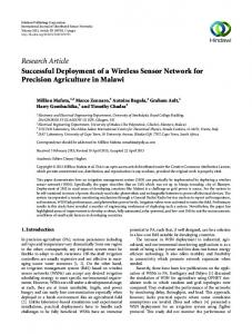
2. CUSTOM DEVELOPED WIRELESS SENSOR SYSTEM Performance monitoring methods are critical in assessing the functionality and condition of a structure. With the rising demand for technologies to improve the accuracy of structural evaluations, newly devised methods to efficiently and effectively monitor the structure performance is sought. A Wireless Sensor System (WSS) which includes a dual axis accelerometer, strain transducer, and a custom conditioning board has been developed in the Laboratory for Intelligent Infrastructure and Transportation Technologies (LIITT) at Clarkson University. An accelerometer and strain transducer connected to a single conditioning board comprise one unit (node) that attaches to a mote, sending the signal wirelessly in packets to another mote connected to a CPU where the data is collected and processed by a custom software platform. A total of twenty wireless units were developed and used in the monitoring. All units are transmitted simultaneously in real time to a single mote which is externally connected to the CPU. For this particular paper, only strain measurements from the wireless system using Bridge Diagnostic Incorporated (BDI) strain transducers (as typically used for load rating purposes) were considered. Figure 1 shows an image of the wireless system with a dual axis accelerometer, strain transducer and the custom designed system hardware. For more information on the developed wireless system can be found in Whelan et al., 2007.
Fig. 1. Custom wireless sensor node with strain transducer and dual-axis accelerometer (Whelan, et al., 2007).
3. BRIDGE CONDITION ASSESSMENT 3.1 Qualitative inspection methods National Bridge Inspection Standards (NBIS) implemented by the FHWA in 1968, direct the frequency and personal required for bridge inspections. Currently a bridge is required to undergo routine inspection at a minimum of once every two years. NBIS uses a condition rating for each component on a scale from zero to nine, where zero is “failed” and nine is “excellent”. However, many states, such as New York, adopt their own rating scale which is approved by FHWA. Each component of the structure is evaluated using visual inspection techniques and assigned a number rating based on the condition. A weighted method (equation 1) incorporating the lowest rating for each
∑RW i
R=
∑W
i
(1)
i
component type (Ri) (i.e. girders, diaphragms, bridge deck, bearings, etc.) and a corresponding weight (Wi) is used by New York State Department of Transportation (NYSDOT), providing a condition number of the structure (Ratay, 2005). Using this information, the condition number is tracked over time where extrapolations and probabilistic measures are incorporated to predict the future condition of the structure. It is important to note that a threshold condition rating is set which requires action be taken on the part of the bridge owner to rehabilitate or replace the structure. This method is a valuable tool in predicting the remaining life expectancy of the bridge. NBIS incorporates in slightly different approach using a sufficiency rating which applies to all bridges in the national highway system. Structural adequacy and safety, serviceability and functional obsolescence, essentially for public use, and special reductions are the four factors that comprise the sufficiency rating (Ratay, 2005). Nonetheless, condition assessments based on visual inspection methods contain levels of subjectivity and lack of accessibility in some cases to parts of the structure. Furthermore, it is difficult to measure the true behavior of the structure using this approach. Therefore, incorporating sensor technology with this process would strengthen the overall rating system. 3.2 Quantitative evaluation methods Field measurements of in-service loading conditions are of utmost importance. Load rating provides the means for measuring a superstructures load capacity. Load demand and capacity are the basis for both rating and design. Maintaining a capacity greater than the load demand is needed to prevent structural collapse. With much of the loading for today’s bridges ranging from light weight vehicles to large tractor trailer trucks, incorporating safety factors are important, particularly when an unknown loading conditions beyond the allowable capacity of the structure are possible. Rating factors are similar as the ratio of the capacity to the live load demand defines a safe level of loading. In any case, equation 2 must be followed where Φ (factor of safety) is greater than or equal to 1. Preferably, due to the probabilistic
nature of the loading and structural deterioration, a factor of safety greater than 1 is recommended. Methodology mentioned from the field deployment below, can be used in obtaining measurements and bridge response parameters related to the capacity of the structure. Furthermore, employing additional methods will allow for the demand to be captured.
capacity ≥ φ demand
(2)
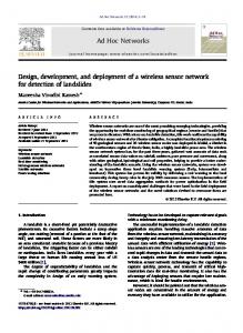
3.3 Field deployment The integral-abutment bridge (shown in Figure 2), constructed in 2004, is 17.07 m (56 ft) in length and comprised of a 241.3 mm (9.5 in) reinforced concrete slab on 4-W36x135 steel girders at 2.74 m (9 ft) center-to-center spacing. Two equally spaced C15x33.9 sections serve as intermediate diaphragms between each girder in addition to MC8x20 end diaphragms. For the testing performed in this study, an appropriate loading vehicle was not available and consequently
Fig. 2. Single-span integral abutment test bridge.
the relative magnitudes of the measured strains were low. To excite the structure, particularly for strain response, passenger vehicle and light truck were used. Since this test was completed under permit but independent of county assistance or supervision, controlled loading independent from the daily traffic was not feasible. Therefore, random load scenarios with one to two vehicles were used and their exact locations unknown. A more accurate assessment would incorporate a controlled loading plan with test vehicles near or at the service design level similar to load testing protocols employed by state agencies. Strain transducers were placed on the top and bottom flanges along an interior girder at the mid-span and both abutment ends. A single transducer was also placed at the mid-span of the bottom flange on the remaining three girders for measuring the girder distribution factors. The complete sensor layout along with an image of a single deployed node containing an accelerometer and strain transducer can be seen in Figure 3. Circled are the locations along girder 3 where both top and bottom strain transducers were placed to measure neutral axis location, section modulus and bending moment.
(a)
Accelerometer
Wireless Sensor Node
Strain Transducer (b) Fig. 3. (a) Sensor location of bridge deployment, (b) Single instrumented node (includes accelerometer that is not used for this paper).
3.4 Field measurements Capacity Stiffness measurements are related to various structural parameters found as a result of this field deployment. Neutral axis location, section modulus, and end fixity define important behavioral characteristics of the superstructure. As mentioned previously, an increase in the neutral axis location and section modulus indicate an increase in rigidity on account of the stiffness contribution from the slab to the primary member (girder). A significant change in these parameters would likely suggest a loss of composite action between the girder and slab, or possibly the presence of Table 1. Neutral axis (NA) and section modulus measurements along girder 3.
Location
NA (cm) [in]
Section Modulus (cm3) [in3]
Mid-span
(97.07) [38.22]
(12,224) [746]
South End
(105.1) [41.37]
(3113) [190]
North End
(96.39) [37.95]
(10,405) [635]
Theoretical
(88.9) [35]
section loss. Table 1 illustrates results captured during the field deployment. The neutral axis and corresponding section modulus parameters were computed at each of the three locations along girder 3 (shown in figure 3a) from top and bottom strain measurements. As is typical, plane section analysis was assumed with no shear lag effects present. The results indicate strong composite action among the slab and girder section, suggesting greater stiffness within the superstructure. Monitoring the position of the neutral axis or change in section loss with time provides a better evaluation of the change in section behavior which may be a result of section deterioration. Furthermore, under the assumption of plane section analysis and no shear lag effects, the results are independent of the loading condition and therefore can be measured on a continuous basis with a permanent monitoring system. The presence of negative strains (depicted in figure 4) at the supports denotes the presence of rotational restraint, increasing structural stiffness. The combination of the above parameters from the measured strain values facilitates the determination of the structural capacity from the live load (i.e. live load section modulus). Comparison of these measurements upon various testing times will provide insight into the change in capacity with the structures age. For multiple continuous span structures and integral abutment designs, locations around the piers (or abutments) that are subjected to high negative moments can cause significant cracking within the concrete deck, potentially resulting in reduced structural stiffness. Therefore, monitoring these locations is necessary.
Fig. 4. Strain output at the north and south abutments of girder 3. Demand With varying loading scenarios possible, demand levels fluctuate. Static or semi-static loading (approximately 8.04 km/h or 5 mph) generates the demand as well as capacity limits from strain readings. A dynamic allowance factor is applied to the static moment demand to account for stresses experienced by the girders above static conditions. Moment distribution factors (DF) describe the demand experienced by each of the primary members. The moment experienced on a particular girder at a specified location compared to the total moment for all girders at that location provides the fraction of the total moment on that section. Equation 3 shows this in symbolic form where S is the section modulus, ε is the strain, and E is the elastic modulus of each girder. Most commonly, the midspan location on each span is the most critical for monitoring as it generally experiences high moment demand. Figure 5 is an illustration of the load distribution at the midspan from a vehicle traveling between girders 1 and 2. In this case, when compared to the theoretical moment DF based on the American Association for State and Highway Transportation Officials (AASHTO) Standard Highway Bridge Specifications (2002) the actual measured values appeared lower.
DF =
S i ε i Ei
∑S ε E i
i
(3) i
As the load is applied to the structure, it is distributed to the nearest primary members then distributed via the slab and diaphragm connections to the remaining structural elements. This would suggest that a shift in the moment distribution factors under a set loading condition would result from a possible change in the load transfer within the superstructure. Additionally, a change in the distribution factor over the girders could result from a change in section modulus or end conditions (Hag-Elsafi, 2006). The consequence is a change in the stiffness of the girder/slab section, adjusting the load response. Furthermore, a change would likely symbolize a loss in the load transfer to other primary members, potentially as a result of a loose diaphragm connection or internal damage within the slab.
Fig. 5. Measured transverse moment distribution factor plots at midspan based on loading on the left hand lane Long-term monitoring Current methods of bridge evaluation utilize visual inspection techniques at a maximum frequency of every two year. Combining qualitative (visual) and quantitative (sensor) measurements offer an improved condition assessment. Upon completion of a bridge inspection, condition ratings are awarded on a scale of acceptability and tracked over the life of the structure. A similar approach with the above mentioned capacity and demand measurements should be considered. With the ease of installation of the sensor units, placement in critical locations of the superstructure would aid in providing a deterioration model for the structure based on actual quantifiable information. Data from Figure 4 illustrate the ability to capture the data wirelessly for processing. This produces, among others, results show in Table 1 as well as Figure 5. As the structure deteriorates a change in the capacity levels are expected. Calibrating the strain measurements to vehicle weight or using a weigh in motion (WIM) system is sufficient to measure the level of demand. These performance characteristics can also be applied to determining the safety factor, or rating factor of the bridge. With the capacity and demand measurements captured by the wireless system, an overall rating factor can be established. Allowable stress and Load Resistance Factor Rating (LRFR) are the two current methods for load rating. LRFR is becoming ever more popular however due to the probabilistic nature of the various potential loading states. The rating factor (RF) using LRFR is given by Equation 4 (AASHTO, 2003) where C is the capacity, DC is the dead-load effect due to structural components and attachments, DW is the dead-load effect due to wearing surface and utilities, P is the permanent loads other than dead loads, LL is the live load effect, IM is the dynamic load allowance and γDC, γDW, γP, and γL are the corresponding LRFD factors with their respective effect component. The numerator of equation 4 represents the available capacity of the structure, while the denominator is the demand. The capacity changes over time due to
RF =
C − γ DC DC − γ DW DW ± γ p P
γ L ( LL + IM )
(4)
deterioration. Demand levels also change with societies needs, as larger vehicles are traveling the roads and demand level increases creating further stress to the structure. As the rating factor declines beyond a certain level, rehabilitation or construction of a replacement bridge may become warranted. The idea of tracking the safety factor over time is presented by Wenzel et al., 2005 in Figure 6. As the state of the bridge reaches a limit point, action by the bridge owner is required. When comparing this model to the deterioration model based on condition ratings from qualitative
measurements, a similar trend can be seen. Combination of both methods would ultimately improve the current state of bridge assessment and potentially aid in preventing future bridge collapses. 3.5
3
Safety Against Failure
B a s e line 2.5
HE A LTHY
E a rly W a rning
2
1.5
IN TE R V E N TION Fa ilure Immine nt
1
0.5
FA ILU R E
0
Time
Fig. 6. Bridge deterioration model (Wenzel et al., 2005)
4. WIRED VERSUS A WIRELESS SYSTEM Cost is a big attraction to the use of wireless sensors for bridge monitoring. Such cost savings come in the form of reducing the cabling required for the sensor as well as the time required for deploying a system. Furthermore, the simplicity of sensor installation and the flexibility to place the sensors in any desired arrangement or location allows for simpler and proper monitoring. Long spanning superstructures can be difficult to instrument with cabled systems as cables are often not long enough or require extra long lengths to tether to a computer system. From a load testing stand point, with the time savings of installation alone, one can argue that more time will become available for monitoring additional bridges and structures that originally had a high degree of difficulty to monitor and instrument. Nonetheless, the cost savings (in its many forms) is one of the biggest attractions to such a system as mentioned in the paper. Initial skepticism of a wireless sensor system was in its ability to transfer significant amounts of data across a network, particularly at higher sampling frequencies. The real time transmission shows the capability of this system to be used in long term field deployments as well as for load testing purposes. The ability of the real time data transmission from this system allows for continuous monitoring and would be beneficial in knowing the change in structural response at the time it occurs so any necessary action can be taken by the appropriate agency. Furthermore, for short term field deployments, such as load testing, monitoring the strains induced to the superstructure in real time are important for determine the safe level of loading. This is of particular interest for both diagnostic and/or proof testing of an in-service deteriorated superstructure. For the mentioned field deployment, 40 channels of both strain and acceleration were measured with 100 percent of the data was transmitted successfully thru a single network.
5. CONCLUSION Methods for improving condition assessment of bridges by incorporating quantitative measurements are of utmost importance to due to the significant deterioration that many of today’s bridges exhibit. Discussed in this paper are methods for improving condition assessment from change in response of various capacity and demand characteristics of the superstructure. A full scale field deployment of a wireless, low-cost and automatic system for structural health management and condition assessment of highway structures was presented to demonstrate the ability of obtaining the necessary behavior characteristics. Strain measurements of a single span integral abutment composite steel and concrete bridge superstructure were obtained in real time with the wireless system under various loading conditions. The results indicated a stiff response, with capacity measurements from the neutral axis and section modulus greatly influenced by the composite action between the reinforced concrete deck and steel girders. Transverse moment distribution factors
indicated load shedding was occurring to all girder members. Integrating such measurements into bridge inspection protocols and the bridge management system (BMS) will aid in providing a better condition assessment.
ACKNOWLEDGEMENTS This research has been funded by the New York State Energy Research and Development Authority (NYSERDA), in collaboration with the St. Lawrence Highway Department, and the New York State Department of Transportation (NYSDOT). The assistance of Dan Nyanjom and Kevin Cross with the field deployment and testing is greatly appreciated. Any opinions, findings, and conclusions or recommendations expressed in this paper are those of the authors and do not reflect the views of the agencies.
REFERENCES American Association for State Highway Transportation Officials (AASHTO)., [Standard specifications for highway bridges], Washington, DC. (2002). American Association for State Highway Transportation Officials (AASHTO)., [Manual for condition evaluation and load and resistance factor rating (LRFR) of highway bridges], Washington, DC. (2003). Aktan, A.E., Pervizpour, M., Catbas,N., Grimmelsoman, K., Barrish, R., Curtis, J., Quin, X., “Information technology research for health monitoring of bridge system,” London, UK, Structural faults &Repair. July 4-6. (2001). Bridge Diagnostic Incorporated (BDI)., “Wireless Structural Testing System (STS-WiFi),” World Wide Web. Online. Available at: http://www.bridgetest.com/products/bdi_sts-wireless.html. Accessed: 7 January. (2008). DeWolf, J.T., D’Attilio, P.F., Feldblum, E.G., and Lauzon, R.G., “Bridge Monitoring Network - Installation and Operation,” Connecticut Department of Transportation, Report No. CT-2217-F-06-10. December. (2006). Hag-Elsafi, O, Kunin, J., “Load testing for Bridge Rating: Route 22 over Swamp River,” New York State Department of Transportation (NYSDOT), Special Report, February. (2006) Lynch, J.P., Wang, Y., Loh, K.J., Yi, J-H., Yun, C-B., “Performance Monitoring of the Geumdang Bridge Using a Dense Network of High-Resolution Wireless Sensors,” Institute of Physics Publishing, Smart Materials and Structures, IOP publishing, UK, 15(2006), October. Pgs. 1561-1575. (2006) Meadows, Jeffery., “Evaluating the success of structural health monitoring methodologies for civil infrastructure,” Honors Thesis, Clarkson University, April. (2006) Phares, B.M., Rolander, D.D., Graybeal, B.A., Washer, G.A., “Studying the Reliability of Bridge Inspection,” Public Roads, December. (2000) Ratay, Robert. T., [Structural Condition Assessment], John Wiley & Sons, Hoboken, NJ. (2005) Wenzel, H and Pichler, D., [Ambient Vibration Monitoring] John Wiley & Sons, Ltd. Hoboken, NJ. pg 18. (2005) Whelan, M.J., Fuchs, M.P., Gangone, M.V., and Janoyan, K.D., “Development of a Wireless Bridge Monitoring System for Condition Assessment using Hybrid Techniques,” Proc. SPIE 6530, San Diego, California. (2007)