Jul 11, 2014 - Therefore, the proposed multifunctional device shows potential ... using two-group 2N Ñ 1 vertical-turning serial-coupled microrings and the grid-type routing ... The coupling region lengths of the optical splitter and optical ...
Multifunctional Polymer Mach–Zehnder Optical Switch/Filter Using Side-Coupled M � N Electrooptic Microring Array Volume 6, Number 4, August 2014 C. T. Zheng Q. Q. Luo X. L. Huang D. M. Zhang
DOI: 10.1109/JPHOT.2014.2332459 1943-0655 Ó 2014 IEEE
IEEE Photonics Journal
Polymer Mach–Zehnder Optical Switch/Filter
Multifunctional Polymer Mach–Zehnder Optical Switch/Filter Using Side-Coupled M � N Electrooptic Microring Array C. T. Zheng, Q. Q. Luo, X. L. Huang, and D. M. Zhang State Key Laboratory on Integrated Optoelectronics, College of Electronic Science and Engineering, Jilin University, Changchun 130012, China DOI: 10.1109/JPHOT.2014.2332459 1943-0655 Ó 2014 IEEE. Translations and content mining are permitted for academic research only. Personal use is also permitted, but republication/redistribution requires IEEE permission. See http://www.ieee.org/publications_standards/publications/rights/index.html for more information.
Manuscript received May 30, 2014; revised June 19, 2014; accepted June 20, 2014. Date of publication June 24, 2014; date of current version July 11, 2014. This work was supported in part by the National Natural Science Foundation of China under Grants 61107021, 61177027, 61275033, and 61261130586; by the Ministry of Education of China under Grants 20110061120052 and 20120061130008; by the Science and Technology Department of Jilin Province of China under Grant 20130522161JH; by the Special Funds of Basic Science and Technology of Jilin University under Grant 201103076; and by the China-Postdoctoral-Science-Foundation-funded project under Grants 20110491299 and 2012T50297. Corresponding author: C. T. Zheng (e-mail: zhengchuantao@jlu. edu.cn).
Abstract: Structure and design were proposed for a kind of novel multifunctional M � N microring array side-coupled Mach–Zehnder interferometer (MZI) electrooptic switch/ filter. The device can be operated as a notch or bandpass filter by applying voltages on the under-reference MZI arm, and it can also serve as an optical switch by applying voltage on microrings. The dependence relations of the device's performances on RSA size (M and N) are thoroughly analyzed and concluded. As a switch, for making driving voltages under both operation states below 5 V, N and M should be within the range of 2–8. For the seven switches (M ¼ 1, 8 � N � 2), their insertion losses are within 0.85–0.35 dB at bar state and within 0.14–1.70 dB at cross state; the crosstalk are within �20.79– �31.11 dB at bar state and within �13.86–�20.36 dB at cross state; and their 3-dB electrical bandwidths are 18.5–30.5 GHz, whereas their 3-dB optical bandwidths for ports 1 and 2 are 18.1–40.0 GHz and 19.0–55.0 GHz, respectively. In addition, the needed energy per bit under 10-GHz switching operations is within 0.092–0.697 pJ. Therefore, the proposed multifunctional device shows potential applications, including filtering, routing, and switching, in optical networks-on-chip. Index Terms: Integrated optoelectronics, microring resonator, electro-optic switch/filter, poled polymer.
1. Introduction Polymer optical switches based on the linear electro-optic (EO) effect [1], [2], as well as optical filters [3], [4], have wide applications in optical communication systems, optical sensing systems, etc. In the past few years, different kinds of polymer EO switches have been numerically proposed by our group since 2008. Generally, there are three kinds described as below. The first kind is based on directional coupler (DC) structure [1], [5], [6], such as standard DC and Y-fed DC. Besides DC, Mach-Zehnder interferometer (MZI) is a simple but preferred structure used in optical switches or filters [7]–[9]. Usually, an MZI switch should be incorporated with other structures, such as DC-assisted MZI and phase-generating coupler (PGC) assisted MZI.
Vol. 6, No. 4, August 2014
6600916
IEEE Photonics Journal
Polymer Mach–Zehnder Optical Switch/Filter
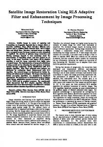
Fig. 1. (a) Structural model of the multifunctional polymer MRA-SC-MZI optical switch/filter using an MZI and a side-coupled M � N MRA. (b) Waveguide cross-section AA0 between an active MRR waveguide and the upper passive MZI waveguide. (c) Under an even and odd M, the M-serialcoupled MRR structure and its light propagation direction.
Due to small dimensions (few �m � �m), ring resonator based devices can be densely integrated onto optoelectronic chips [10]–[13]. Therefore, the third kind of EO switch reported by our group is based on microring resonator (MRR) structure [14], [15], such as the MRR switch using two-group 2N þ 1 vertical-turning serial-coupled microrings and the grid-type routing switch matrix based on two-ring cross-coupling resonators. As a difference from the above switching configurations, combining the advantages of interference effect of MZI and phase-tuning effect of MRR, a kind of novel EO switch using M � N microring array side-coupled MZI (MRA-SC-MZI) structure is proposed, where N-group M-serialcoupled EO micorings are side-coupled with one arm of MZI. Through optimization, the devices with N � 8 and M � 2 can perform normal switching operations with acceptable crosstalk and insertion loss, and their operation voltages are all below 5 V. An impressive advantage of this structure is that the driving voltages of the proposed switching devices (8 � N � 2 and M ¼ 1) is reduced by 10 � 250 times compared with the traditional MZI EO switch; and also large optical bandwidth (> 18 GHz) and low switching energy (G 1 pJ/bit) are also observed for the proposed devices. Furthermore, by depositing a pair of microstrip electrodes under and upon the under reference MZI arm, the device can also be operated as a kind of optical filters by applying different voltages on these electrodes (creating different phase shift), such as notch filter or band-pass filter around the central wavelength of 1550 nm. In this case, the proposed device shows potential applications, including signal filtering, routing and switching, in optical networks on chip (ONoC). This multifunctional structure, to the best of our knowledge, has never been reported before. The structure of this paper is organized as follows. First, in Section 2, device structure and transfer function of the multifunctional polymer MRA-SC-MZI switch/filter are proposed, and formulations on output powers, insertion loss and crosstalk are obtained based on coupled mode theory (CMT), ring resonance theory and transfer matrix method. Then in Section 3, structural parameters are optimized, including waveguide core size, ring radius, coupling gaps, transitive bending waveguide radius, etc. Furthermore in Sections 4 and 5, by means of the presented formulas, filtering and switching characteristics are analyzed, involving notch and band-pass filtering functions, switching voltage, switching spectrum, electrical bandwidth, optical bandwidth, switching power, etc. Comparisons are made between the proposed MRA-SC-MZI switch and other reported MZI or MRR-assisted MZI devices. Finally, a conclusion is reached in Section 6.
2. Device Structure and Formulation 2.1. Structure of MRA-SC-MZI Optical Switch/Filter The structural model of the polymer MRA-SC-MZI optical switch/filter is shown in Fig. 1(a). This multifunctional device consists of input/output waveguides, two passive DCs served as mode splitter and mode combiner, eight arc-transitive bending waveguides, and two MZI arms. One arm couples with N groups of M-serial-coupled EO microrings (with identical radius r ), and
Vol. 6, No. 4, August 2014
6600916
IEEE Photonics Journal
Polymer Mach–Zehnder Optical Switch/Filter
another one is an active waveguide served as a phase shifter with an applied bias voltage of Ubias . The coupling region lengths of the optical splitter and optical combiner are both L1 , and the bending radius of the arc-transitive waveguide is R. An extending waveguide with length of L2 is used to couple with the MRR waveguide. For the 3-dB DC, the gap between two coupling waveguides is d . For the M � N MRA, there are N groups of M-serial-coupled microrings. The gap between two adjacent groups is L3 , which should be taken large enough for decreasing the coupling effect between two adjacent groups. Within each group, the coupling gap between the upper MZI waveguide and MRR waveguide is hCR , and that between two adjacent microrings is hRR . The length of the phase-shifter can be expressed as � ðN � 1ÞL3 þ ðN � 1Þ � ð2r þ wr Þ þ 2L2 ; N � 1 Lpha ¼ (1) 2L2 ; N ¼ 0: The cross-section view AA0 between an MRR waveguide and the upper MZI waveguide is shown in Fig. 1(b). The electrode is only deposited on microrings, for static operation, the applied direct-current voltage is U, and for dynamic operation, the applied time-dependent signal is ug ðtÞ. The MRR waveguide layers are as: upper confined layer/upper electrode/upper buffer layer/EO core layer/under buffer layer/under electrode/Si substrate. Let t1 , t2 and t3 be the thicknesses of the core, buffer layer and electrode, respectively, and let wr be the width of the rectangular waveguide. For the passive waveguide, the under buffer layer thickness is t2 þ t3 . Because of bending, the core width of MRR waveguide is slightly different from that of the channel waveguide (defined as wc ,) for obtaining index-match between the two waveguide ðU ¼ 0 VÞ. Under the wavelength of 1550 nm, relative material parameters are taken as: the refractive index of the EO polymer material (AJL8/APC) n10 ¼ 1:59, its bulk amplitude attenuation coefficient �10 ¼ 0:25 dB/cm, and its EO coefficient �33 ¼ 68 pm/V [16], [17]; the refractive index of the upper/under buffer layer material [P(PFS-GMA)] n20 ¼ 1:461, and its bulk amplitude attenuation coefficient �20 ¼ 0:25 dB/cm [18]; the electrode is made of aurum, its refractive index n30 ¼ 0:19, and its bulk extinction coefficient �30 ¼ 6:1 [19]. The refractive index of the left/ right/center cladding will greatly affect bending radius and loss, which will be discussed in Section 3.1.
2.2. M-Serial-Coupled Microring Resonator According to EO modulation theory, the variation of refractive index �n10 of the EO core material of MRR waveguide versus U is n3 n 2 �33 U 1 3 �n10 ðUÞ ¼ n10 �33 E ¼ � 102 20 2 � 2 2 2n10 t2 þ n20 t1
(2)
where U can be equal to zero or not. The refractive index of the EO core material n10 will be changed to n10 þ �n10 . Then the mode propagation constant in the active waveguide can be regarded as a function of U, denoted by �R ðUÞ, and accordingly, the optical mode loss can be denoted by �R ðUÞ. For the ith M-serial-coupled microring resonator, under an even and odd M, the resonator structure and its light propagation direction are shown in Fig. 1(c). For microring Rji , let aji and bji ðj ¼ 1; 2; . . . MÞ be the light amplitudes of the lower coupling point, and a01i and b1i0 ðj ¼ 1; 2; . . . M � 1Þ be those of the upper coupling point, which can be seen from Fig. 1(c). Define �ji and tji ðj ¼ 1; 2; . . . M � 1Þ as the amplitude coupling ratio and amplitude transmission ratio between Rji and Rjþ1;i , respectively, and they satisfy the relation of �2ji þ tji2 ¼ 1. The coupling relation between Rj;i and Rjþ1;i can be described as the following matrix form: � � � �� � 1 tji �1 a0ji ajþ1;i ¼ (3) 0 : bjþ1;i j�ji 1 �tji bji
Vol. 6, No. 4, August 2014
6600916
IEEE Photonics Journal
Polymer Mach–Zehnder Optical Switch/Filter
Since a0ji ¼ bji expð�j�i Þ and bji0 ¼ aji expðj�i Þ, then we have � � � � � �� � 1 ajþ1;i �expðj�ji Þ tji expð�j�ji Þ aji a ¼ ¼ Qi ji (4) �t bjþ1;i expðj� Þ expð�j� Þ b bji j�ji ji ji ji ji � � �expðj�ji Þ tji expð�j�ji Þ 1 where �ji ¼ �r ð�R � j�R Þ, Qji ¼ j�ji , and j ¼ 1; 2; . . . ; M � 1. �tji expðj�ji Þ expð�j�ji Þ If we let �1i ¼ �2i ¼ � � � ¼ �M�1;i ¼ �R1 , �1i ¼ �2i ¼ � � � ¼ �M�1;i ¼ �RR , and t1i ¼ t2i ¼ � � � ¼ tM�1;i ¼ tRR , then Q1i ¼ Q2i ¼ � � � ¼ QM�1;i ¼ QR ði ¼ 1; 2; 3; . . . ; NÞ. We can obtain the following relation between a1i , b1i and aM�1;i , bM�1;i : � � � � � � a1;i aM;i M�1 a1;i ¼ QM�1;i QN�2;i . . . Q1;i b ¼ QR : (5) b b M;i
1;i
1;i
Then, we have aM;i ¼ QRM�1 ð1; 1Þa1;i þ QRM�1 ð1; 2Þb1;i , and bM;i ¼ QRM�1 ð2; 1Þa1;i þ QRM�1 ð2; 2Þb1;i . Noticing that aM;i ¼ bM;i expð�j�M;i Þ ¼ bM;i expð�j�R2 Þ, we have QRM�1 ð1; 2Þ � QRM�1 ð2; 2Þ expð�j�R2 Þ bM;i ¼ f1 bM;i QRM�1 ð2; 1ÞQRM�1 ð1; 2Þ � QRM�1 ð1; 1ÞQRM�1 ð2; 2Þ Q M�1 ð2; 1Þ expð�j�R2 Þ � QRM�1 ð1; 1Þ bM;i ¼ f2 bM;i ¼ M�1 R QR ð2; 1ÞQRM�1 ð1; 2Þ � QRM�1 ð1; 1ÞQRM�1 ð2; 2Þ
a1;i ¼
(6)
b1;i
(7)
where f1 ¼ ððQRM�1 ð1; 2Þ�QRM�1 ð2; 2Þ expð�j�R2 ÞÞ=ðQRM�1 ð2; 1ÞQRM�1 ð1; 2Þ�QRM�1 ð1; 1ÞQRM�1 ð2; 2ÞÞÞ, f2 ¼ ððQRM�1 ð2; 1Þ expð�j�R2 Þ � QRM�1 ð1; 1ÞÞ=ðQRM�1 ð2; 1ÞQRM�1 ð1; 2Þ � QRM�1 ð1; 1ÞQRM�1 ð2; 2ÞÞÞ, and �R2 ¼ 2�r ð�R � j�R Þ. At the coupling point between the ring R1i ð1 � I � NÞ and the upper MZI arm, let a0i and b0i be the input and output light amplitudes of the MZI waveguide, as marked in Fig. 1(a). Define �CRi and tCRi as the amplitude coupling ratio and amplitude transmission ratio between R1i ð1 � i � 2 NÞ and the upper MZI arm, respectively, which satisfy the relation �2CRi þ tCRi ¼ 1 and depend on hCR and . The coupling relation between R1i and the upper MZI arm can be described as b0i ¼ tCRi a0i � j�CRi a1i b1i ¼ � j�CRi a0i þ tCRi a1i :
(8) (9)
We can derive from (6)–(9) that b0i ¼
f1 � tCRi f2 a0i : tCRi f1 � f2
(10)
2.3. Transfer Function of Two MZI Arms For the upper MZI arm, define AE1 and AE2 as the input and output light amplitudes, respectively. Then we get the following relations: AE 2 ¼ exp½�jð�c0 � j�c0 ÞL2 �b0N a0i ¼ exp½�jð�c0 � j�c0 ÞðL3 þ 2r þ wr Þ�b0;i�1 ; a0i ¼ exp½�jð�c0 � j�c0 ÞL2 �AE1
1�i �N
(11a) (11b) (11c)
where �c0 and �c0 are mode propagation constant and amplitude loss coefficient of the passive straight MZI waveguide, respectively. Let �CR1 ¼ �CR2 ¼ � � � ¼ �CRi ¼ �CR and tCR1 ¼ tCR2 ¼ � � � ¼ tCRi ¼ tCR ði ¼ 1; 2; 3 . . . NÞ. Then, using (10) and (11a)–(11c), the relation between AE1 and AE2 can be expressed as (h iN f1 �tCR f2 AE2 exp½�jðN �1Þð�c0 �j�c0 ÞðL3 þ2r þwr Þ�exp½�j2ð�c0 �j�c0 ÞL2 �; N � 1 (12) t f �f ¼ Tupp ¼ CR 1 2 AE1 exp½�j2ð�c0 �j�c0 ÞL2 �; N ¼ 0.
Vol. 6, No. 4, August 2014
6600916
IEEE Photonics Journal
Polymer Mach–Zehnder Optical Switch/Filter
Note that, tRR and �RR are both the functions of U, so Tupp will also be a function of U, written as Tupp ¼ Tupp ðUÞ:
(13)
In the lower active MZI arm, define BE1 and BE2 as the input and output light amplitudes, respectively. The variation of its core refractive index �n10 can be expressed by (2), and the mode propagation constant and mode optical loss can be regarded as a function of Ubias , denoted by �C ðUbias Þ and �C ðUbias Þ, respectively. Then, the transfer function of the phase-shifter is � � Tund ðUbias Þ ¼ BE2 =BE1 ¼ exp �jð�C � j�C ÞLpha : (14)
2.4. Formulation on Output Powers Define ’d1 and ’d2 as the angular coupling coefficients of the splitter and combiner, respectively, which can be expressed as ’d1 ¼ ’d2 ¼ ’d ¼ L1 �=ð2L0 Þ;
(15)
where L0 ¼ �=ð2K Þ is coupling length, and K is the coupling coefficient of the DC. Then the amplitude transfer matrix of the splitter and that of the combiner can both be written as
cos’d �jsin’d TDC;1 ¼ TDC;2 ¼ expð��c0 L1 Þ : (16) �jsin’d cos’d The output powers are analyzed in terms of two situations. 1) Under the case of light inputting into the upper waveguide only: Let the light with an original amplitude of A0 ¼ R0 input into the upper waveguide only, e.g., P10 ¼ P0 ¼ jA0 j2 ¼ jR0 j2 and P20 ¼ jB0 j2 ¼ 0. Through the function of the optical splitter, we obtain the light amplitudes output from the splitter as, respectively
R0 cos’d �jsin’d A1 : (17) ¼ expð��c0 L1 Þ B1 �jsin’d cos’d 0 After propagation through the transitive waveguide, the two amplitudes input into the upper MZI arm and phase-shifter are, respectively AE1 ¼ R0 expð��c0 L1 Þcos’d expð�j2�arc1 Þ
(18a)
BE1 ¼ R0 expð��c0 L1 Þð�jsin’d Þexpð�j2�arc1 Þ
(18b)
where arc1 ¼ ð�R=2Þð�arc1 � j�arc1 Þ is the mode phase shift of the arc waveguide, and �arc1 and �arc1 are the mode propagation constant and mode amplitude loss coefficient of the passive arc bending waveguide, respectively. Then through the upper MZI branch, the output light amplitude is � � f1 � tCR f2 N AE 2 ¼ TMRR AE 1 ¼ exp½�jðN � 1Þð�c0 � j�c0 ÞðL3 þ 2r þ wr Þ� tCR f1 � f2 �exp½�j2ð�c0 � j�c0 ÞL2 �R0 expð��c0 L1 Þcos’d expð�j2�arc1 Þ; N � 1: (19) Besides, we obtain the amplitude BE2 input into the arc transitive waveguide as � � BE2 ¼ BE1 Tpha ¼ R0 expð��c0 L1 Þð�jsin’d Þ exp �jð�c � j�c ÞLpha expð�j2�arc1 Þ: Finally, the two output light amplitudes are expressed as
A3 jin1 AE2 expð�j2�arc1 Þ cos’d �jsin’d : ¼ expð��c0 L1 Þ B3 jin1 BE2 expð�j2�arc1 Þ �jsin’d cos’d
Vol. 6, No. 4, August 2014
(20)
(21)
6600916
IEEE Photonics Journal
Polymer Mach–Zehnder Optical Switch/Filter
Combining (19)–(21), when N � 1, the output light amplitudes are A3 jin1 ¼ R0 expð�2�c0 L1 Þ expð�j4 arc1 Þ (� � f1 � tCR f2 N exp½�jðN � 1Þð�c0 � j�c0 ÞðL3 þ 2r þ wr Þ� � tCR f1 � f2 � � � exp½�j2ð�c0 � j�c0 ÞL2 �ðcos’d Þ � exp �jð�C � j�C ÞLpha gðsin’d Þ2
)
2
(22)
B3 jin1 ¼ � jR0 sin’d cos’d expð�2�c0 L1 Þexpð�j4 arc1 Þ (� � f1 � tCR f2 N exp½�jðN � 1Þð�c0 � j�c0 ÞðL3 þ 2r þ wr Þ�exp½�j2ð�c0 � j�c0 ÞL2 � � tCR f1 � f2 ) � � þ exp �jð�C � j�C ÞLpha : Finally, the output powers are obtained as � �2 � �2 in1 in1 ðdBÞ ¼ 10lg�A3 jin1 =R0 � ; Pout2 ðdBÞ ¼ 10lg�B3 jin1 =R0 � : Pout1
(23)
(24)
2) Under the case of light inputting into the lower waveguide only: In this case, P10 ¼ jA0 j2 ¼ 0, and P20 ¼ P0 ¼ jB0 j2 ¼ jR0 j2 . The output light amplitudes from the device are obtained as follows: A3 jin2 ¼ � jR0 sin’d cos’d expð�2�c0 L1 Þexpð�j4 arc1 Þ (� � f1 � tCR f2 N exp½�jðN � 1Þð�c0 � j�c0 ÞðL3 þ 2r þ wr Þ� � tCR f1 � f2 ) � � � exp½�j2ð�c0 � j�c0 ÞL2 � þ exp �jð�C � j�C ÞLpha
(25)
B3 jin2 ¼ � R0 expð�2�c0 L1 Þexpð�j4 arc1 Þ (� � f1 � tCR f2 N exp½�jðN � 1Þð�c0 � j�c0 ÞðL3 þ 2r þ wr Þ� � tCR f1 � f2
) � � 2 � exp½�j2ð�c0 � j�c0 ÞL2 �ðsin’d Þ � exp �jð�C � j�C ÞLpha ðcos’d Þ : 2
Then, the output powers under this case are � �2 � �2 in2 in2 ðdBÞ ¼ 10lg�A3 jin2 =R0 � ; Pout2 ðdBÞ ¼ 10lg�B3 jin2 =R0 � : Pout1
(26)
(27)
Furthermore, under the two inputting cases, in order to enable A3 jin2 ¼ B3 jin1 and A3 jin1 ¼ B3 jin2 , e.g., obtain the same cross-state and bar-state operations, it is required that cos’d ¼ sin’d . Then, we have ’d ¼ �L1 =ð2L0 Þ ¼ �=4, and L1 ¼ L0 =2.
3. Design Scheme and Optimization 3.1. Left/Right Cladding Index Selection Firstly, we assume that the left/right/center cladding material has no absorption. With the analysis method on mode characteristics of the bending waveguide presented in [20], the effect of left/right cladding index ðn40 Þ on the amplitude bending loss coefficient ð�R Þ of the mode in MRR waveguide is shown in Fig. 2(a), where t2 ! 1, wr ¼ t1 ¼ 1:7 �m, and r ¼ 10; 20; 50; and 100 �m. One can find that under certain r , �R increases exponentially as the increase of n40 , and though a large R will be helpful for decreasing bending loss, the device integration
Vol. 6, No. 4, August 2014
6600916
IEEE Photonics Journal
Polymer Mach–Zehnder Optical Switch/Filter
Fig. 2. (a) Effects of n40 on bending loss coefficient ð�R Þ of the MRR waveguide and (b) curve of the allowed maximum value of n40 versus bending radius r for obtaining an amplitude bending loss of G 10�3 dB/cm, where wr ¼ t1 ¼ 1:7 �m, t2 ! 1, and �40 ¼ 0. (c) Effective refractive indices of y y y , E10 and E01 modes versus core width wr of MRR waveguide without considering bending efE00 y mode versus core width wr of MRR waveguide considering fect; effective refractive index of E00 y mode versus core width wr considering bending effect; curve bending effect. (d) Curve of nR of E00 y of nC0 of E00 mode versus core width wc of the upper MZI waveguide.
decreases. Therefore, n40 should be as small as possible so as to decrease ring radius. Fig. 2(b) shows the curve of the allowed maximum value of n40 versus bending radius r for obtaining lower than 10�3 dB/cm amplitude bending loss. One can find that in order to decrease �R below 10�3 dB/cm and obtain G 20 �m ring radius, n40 should be G 1.16. Therefore, air, with an index of only 1.0 as well as no absorption loss, is adopted as the left/right/center cladding layer, e.g., n40 ¼ 1:0 and �40 ¼ 0.
3.2. Waveguide Core Size Optimization 1) First, by using our presented analysis theory on metal oxide semiconductor (MOS) waveguide in [5], the upper/under buffer layer thickness is taken as t2 ¼ 2:5 �m, and the electrode thickness is taken as b3 ¼ 0:2 �m. Under the above parameters, the mode loss caused by electrode absorption will be the smallest, and the electrode and buffer layer can be regarded to be half-infinitely thick. y y 2) Without considering the bending effect [21], curves of the effective indices of E00 , E01 , and y E10 modes versus wr are shown in Fig. 2(c), where wr ¼ t1 . For assuring single-mode propagation in microring rectangular waveguide, wr ¼ t1 ¼ 1:7 �m. Considering bending effect [22], under the same waveguide size, the mode effective refractive index of a straight waveguide is smaller than that of a bending waveguide. When r ¼ 19:49 �m, we have nR ¼ 1:5189, under the case of applying no voltage. 3) When U ¼ 0 V, phase match is needed between the upper passive MZI waveguide and y MRR waveguide. Fig. 2(d) also exhibits the curve of nR of E00 mode versus wr considering bendy ing effect. Besides that curve, for the passive MZI waveguide, curve of nC0 of E00 mode versus core width wc is shown in Fig. 2(d), where t1 ¼ 1:7 �m. When we select wc ¼ 1:85 �m and wr ¼ 1:7 �m, the channel and microring possess identical mode effective refractive index ½nC0 ¼ nR ðU ¼ 0 VÞ ¼ 1:5189�. Since the bending radius is sufficiently large, the mode loss in MRR waveguide is almost equal to that of the passive channel waveguide, which are �C0 ¼ �R ðU ¼ 0 VÞ ¼ 0:256 dB/cm. We also ignore the influence of applied voltage to mode optical loss, then for the active MRR waveguide, �R ðUÞ �R0 ðU ¼ 0 VÞ ¼ 0:256 dB/cm, and for the active lower MZI waveguide �C ðUbias Þ �C0 ¼ 0:256 dB/cm.
3.3. Coupling Gaps Optimization By means of coupled mode theory, Fig. 3(a) shows the amplitude coupling ratio �RR and �CR versus the coupling gaps hRR and hCR at 1550 nm wavelength and U ¼ 0 V, where t1 ¼ 1:7 �m, wC ¼ 1:85 �m, and wR ¼ 1:7 �m. As the two central coupling gaps increase, the two amplitude coupling ratios decrease. For getting a considerable large coupling effect, we choose hCR ¼ 0:14 �m and hRR ¼ 0:68 �m, and the corresponding �CR and �RR is about 1:25 � 10�1 and 6:85 � 10�3 .
Vol. 6, No. 4, August 2014
6600916
IEEE Photonics Journal
Polymer Mach–Zehnder Optical Switch/Filter
Fig. 3. (a) Coupling ratio �CR between the upper MZI waveguide and MRR waveguide and �RR between two MRR waveguides versus coupling gaps hCR and hRR , where U ¼ 0 V. (b) For the directional coupler (splitter or combiner), curves of coupling coefficient K and coupling length L0 versus coupling gap d . (c) For MRR waveguide, curves of fundamental mode effective index nR and bending radius r versus resonance order m. The inset exhibits the effects of bending radius r on bending power loss coefficient 2�b . (d) For the arc-transitive waveguide, curves of fundamental mode effective index nC and bending power loss coefficient 2�b versus bending radius R.
The coupling region length of the splitter (or combiner) is dependent on the coupling gap between two rectangular waveguides. Fig. 3(b) shows the curves of coupling coefficient K and coupling length L0 versus coupling gap d . As shown in the figure, d cannot be taken too large, otherwise K becomes too small and L0 becomes too large, leading to long waveguide length; d cannot be taken too small, otherwise the fabrication accuracy will be highly required for perfect 3 dB splitting/combining function. Therefore, we select d ¼ 0:8 �m, the corresponding coupling length L0 ¼ 1547:88 �m, and the coupling region length is determined to be L1 ¼ L0 =2 ¼ 773:94 �m.
3.4. Bending Radius Optimization for MRR For the MRR bending waveguide, the bending radius should satisfy the following resonance equation: 2�rnR ¼ m ;
(28)
where m is resonance order, and nR is mode effective index that is also dependent on bending radius. Fig. 3(c) shows the curves of fundamental mode effective index nR and bending radius r versus resonance order m, where wr ¼ t1 ¼ 1:7 �m. As m increases, nR decreases and r increases. Properly, we select m ¼ 120, and the bending radius is determined to be r ¼ 19:49 �m. On another aspect, the bending will cause extra bending loss. The inset of Fig. 3(c) exhibits the effect of bending radius r on bending power loss coefficient 2�b . It can be observed that 2�b decreases exponentially as the increase of r . When r exceeds 19 �m, 2�b is dropped below 10�8 dB/cm, which can be neglected compared with propagation loss 2�R .
3.5. Bending Radius Optimization for Arc-Transitive Waveguides For the arc-transitive waveguide, the bending radius need not satisfy the resonance condition. However, the bending radius should be designed with low bending loss and small index mismatch between straight waveguide and bending waveguide. Fig. 3(d) shows the curves of fundamental mode effective index nC and bending power loss coefficient �b versus bending radius R, where wc ¼ 1:85 �m, and t1 ¼ 1:7 �m. For decreasing the difference between the index of bending waveguide and that of straight waveguide, the bending radius of arc-transitive waveguide is taken as R > 40 �m, and in this case, the mode bending power loss is less than 10�24 dB/cm, and the mode effective index is about 1.5208.
4. Filtering Characteristics Through the optimizations performed in Sections 3.1–3.5, the final optimized parameters of the device are wr ¼ 1:7 �m, wc ¼ 1:85 �m, t1 ¼ 1:7 �m, t2 ¼ 2:5 �m, t3 ¼ 0:2 �m, hCR ¼ 0:14 �m, hRR ¼ 0:68 �m, m ¼ 120, r ¼ 19:49 �m, R ¼ 40 �m, and L2 ¼ L3 ¼ 20 �m.
Vol. 6, No. 4, August 2014
6600916
IEEE Photonics Journal
Polymer Mach–Zehnder Optical Switch/Filter
Fig. 4. Curves of output powers Pout1 and Pout2 versus � =� for the devices with different N and M. (a) N ¼ 1, M ¼ 1; 3; and 5. (b) N ¼ 1, M ¼ 2; 4; and 6. (c) N ¼ 2, M ¼ 1; 2; 3; and 4. (d) N ¼ 3, M ¼ 1; 3; and 5. (e) N ¼ 3, M ¼ 2; 4; and 6. (f) N ¼ 4, M ¼ 1; 2; 3; and 4. (g) Maximum power contrast versus M under different N. (h) The required � =� for obtaining the maximum Pout1 , the minimum Pout1 , and the same Pout1 and Pout2 .
Fig. 5. Bandpass and notch filtering characteristics for the devices with different N and M. (a) Bandpass, N ¼ 1, M ¼ 1; 5. (b) Notch, N ¼ 1, M ¼ 1; 5. (c) Bandpass, N ¼ 2, M ¼ 1; 5. (d) Notch, N ¼ 2, M ¼ 1; 5. (e) Bandpass, N ¼ 3, M ¼ 1; 5. (f) Notch, N ¼ 3, M ¼ 1; 5. (g) Bandpass, N ¼ 4, M ¼ 1; 5. (h) Notch, N ¼ 4, M ¼ 1; 5.
4.1. Output Powers Versus Phase-Shift Define � ðUbias Þ ¼ �C Lpha as the phase generated by the lower MZI arm. When no voltage is applied on microrings, e.g. U ¼ 0 V, the relations between the output powers (Pout1 and Pout2 ) and � =� are investigated under 1550 nm wavelength, as shown in Fig. 4(a)–(f). We can draw the following conclusions. i) Under an odd N, the variation trends of Pout1 and Pout2 under an odd M and those under an even M are opposite, as proven by the comparison between Fig. 4(a) and (b) for N ¼ 1 and the comparison between Fig. 4(d) and (e) for N ¼ 3. ii) Under an even N, Pout1 and Pout2 under an odd M and those under an even M show the same trends, as proven by the results in Fig. 4(c) for N ¼ 2 and the results in Fig. 4(f) for N ¼ 4. As the increase of N or M, because of the increase of propagation loss and coupling loss of the increased rings, the power contrast value (defined as jmaxðPout1 Þ � minðPout2 Þj) between the two ports becomes smaller, as shown in Fig. 4(g). It can also be found that N and M cannot be taken too large, otherwise, the power contrast ratio decreases rapidly. Under the following three requirements for obtaining the maximum Pout1 , the minimum Pout1 , and an identical Pout1 and Pout2 , the needed phases for each device under different N are shown in Fig. 4(h). For each device, when we set � =� to be the required value for obtaining the maximum Pout1 , the device can be treated as bandpass filter around 1550 nm; when we set � =� to be the required value for obtaining the minimum Pout1 , the device can be treated as a notch filter around 1550 nm.
4.2. Bandpass and Notch Filtering Functions (@1550 nm) When U ¼ 0 V, the filtering characteristics of each device with different N and M are investigated, as shown in Fig. 5. Note that for each device, the required bias voltages are different for realizing bandpass and notch filtering functions, which can be found in Fig. 4(h). Actually, one can find from Fig. 5 that only the device with N ¼ 1 and M ¼ 1 exhibits standard bandpass and notch filtering characteristics. As M þ N � 2, the filtering functions are not as favorable as those of N ¼ 1 and M ¼ 1, because that the increased rings causes oscillation in the spectrum around 1550 nm, which worsens the filtering performances. However, for each device with different N, bandpass and notch filtering characteristics can be achieved under a slightly larger M, e.g., M ¼ 5, as shown in Fig. 5(a)–(h).
Vol. 6, No. 4, August 2014
6600916
IEEE Photonics Journal
Polymer Mach–Zehnder Optical Switch/Filter
Fig. 6. Curves of output powers Pout1 and Pout2 versus U applied on MRA under 1550 nm wavelength, where the light is input into the upper port only: M ¼ 1. (a) N ¼ 1; 2. (b) N ¼ 3; 4. (c) N ¼ 5; 6. (d) N ¼ 7; 8. (e) Curves of Pout2 � Pout1 versus U for different MRA-SC-MZI EO switches.
Fig. 7. Curves of output powers Pout1 and Pout2 versus the applied voltage U applied on the MRA under 1550 nm wavelength, where the light is input into the upper port only: N ¼ 1. (a) M ¼ 1; 2; 3. (b) M ¼ 4; 5. (c) M ¼ 6; 7. (d) M ¼ 8; 9; 10. (e) Curves of Pout2 � Pout1 versus U for different MRASC-MZI EO switches.
5. Switching Characteristics 5.1. Static Switching Performances Versus N ðM ¼ 1Þ By using (22)–(24), for different MRA-SC-MZI EO switches with M ¼ 1 and N ¼ 1 � 8, Fig. 6(a)–(d) present the curves of output powers Pout1 and Pout2 versus voltage U applied on the MRA under 1550 nm wavelength, where the light inputs into the upper port only. For the switches with N ¼ 1 � 8, as shown in Fig. 6(b)–(d), 1 � 8 state-exchanges are observed for the 6 switches, respectively, and the two states belong to the ðN � 1Þ-th state-exchange are chosen as the operation states for each device. The above phenomenon can be attributed to the voltage-induced phase-shift variation on the MRA. As the voltage is small, the resonance wavelength of the rings is not shifted far away enough from 1550 nm, light will continue transferring into the rings, but their amount becomes smaller as the voltage gets larger; the phase-shift accumulation in the microrings is different under different voltages, which causes exchange between the two output powers. However, as the voltage is large enough, the resonance wavelength of the rings is far away enough from 1550 nm, no light will couple into the rings, and the output powers will become steady state (e.g., Pout2 becomes the maximum). Besides, under the driving voltage of 0 V, the difference between the phase-shift resulting from odd-number of rings and that from even-number of rings leads to different operation state for the switch with different number of microrings, which can also be found in Figs. 4 and 6–8. The relations between the device's crosstalk (CTbar and CTcross ) and the difference value Pout2 � Pout1 can be described as �CTcross ¼ Pout2 � Pout1 ; CTbar ¼ Pout2 � Pout1 ; Fig. 6(e) shows the Pout1 > 0, the switch Pout1 G 0, the switch minimum crosstalk at
Pout2 > Pout1
(29)
Pout1 > Pout2 :
(30)
curves of Pout2 � Pout1 versus U for different switches. When Pout2 � is under cross state, and the value represents �CTcross ; when Pout2 � is under bar state, and the value represents CTbar . For obtaining the both operation states, the driving voltages for the switches with N ¼ 2 � 8
Vol. 6, No. 4, August 2014
6600916
IEEE Photonics Journal
Polymer Mach–Zehnder Optical Switch/Filter
Fig. 8. Curves of output powers Pout1 and Pout2 versus the applied voltage U applied on the MRA under 1550 nm wavelength, where the light is input into the upper port only. (a) M ¼ N ¼ 1. (b) M ¼ N ¼ 2. (c) M ¼ N ¼ 3. (d) M ¼ N ¼ 4. (e) M ¼ N ¼ 5. (f) M ¼ N ¼ 6. (g) M ¼ N ¼ 7. (h) M ¼ N ¼ 8. (i) M ¼ N ¼ 9. (j) M ¼ N ¼ 10.
are taken as those with the maximum �CTcross and those with the minimum CTbar . The driving voltages (defined as U� ) under cross state of the 7 switches are 0, 0.56, 0.96, 1.32, 1.67, 2.00, and 2.32 V, respectively; whereas those (defined as U¼ ) under bar state are 0.96, 1.67, 2.32, 2.96, 3.58, 4.21, and 4.83 V, respectively; and their switching voltages (defined as Us ¼ jU� � U¼ j) are 0.96, 1.11, 1.36, 1.64, 1.91, 2.21, and 2.51, respectively. Since the MRA-SC-MZI EO switch with N ¼ 1 only has one state-exchange, U¼ is taken as 0 V, and U� is taken as 10 V for obtaining as low as �20 dB crosstalk.
5.2. Static Switching Performances Versus M ðN ¼ 1Þ Similarly, under N ¼ 1, the relations between the output powers from the devices with different M versus U are investigated, as shown in Fig. 7(a)–(d). Fig. 7(e) shows the curves of Pout2 � Pout1 versus U. One can observe from Fig. 7(e) that, though the devices with even M (cross state) and those with odd M (bar state) are under different operation states at U ¼ 0 V (the reason can be attributed to difference between the phase-shift resulting from odd-number of rings and that from even-number of rings when U is not sufficiently large), the curves will finally turn out to be the same operation state (e.g., cross-state) as U gets sufficiently large, as also proven by Fig. 7(a)–(d). As the increase of M from 2 to 10, the switching voltages for the 9 devices are 0.84, 0.82, 0.52, 0.5, 0.37, 0.36, 0.29, 0.28, and 0.24 V, respectively; whereas the crosstalk under bar state are within �20:79 � �6:53 dB and those under cross state are within �20:36 � �5:29 dB.
5.3. Static Switching Performances Versus M and N ðM ¼ NÞ As M ¼ N, the dependences of Pout1 and Pout2 on M (or N) are shown in Fig. 8. When M and N increases from 1 to 10, according to the selection rule on operation states, the devices can be divided into three kinds. i) When M ¼ N ¼ 1, the operation states which can be only chosen are shown in Fig. 8(a), and the driving voltages are 0 and 10 V, respectively. ii) When M ¼ N ¼ 2, the operation states are chosen and shown in Fig. 8(b), and the driving voltages are 0 and 1.44 V, respectively. iii) When M ¼ N � 3, the rule on choosing operation states are the same, as shown in Fig. 8(c)–(j). As N and M both increase, the driving voltages get larger but the crosstalk drops. Furthermore, through the comparisons among Figs. 6–8, we can conclude that i) the increase of N will result in the increase of driving voltage and result in the decrease of crosstalk; ii) the increase of M will result in the decrease of driving voltage and result in the increase of crosstalk; iii) the driving voltages are primarily dependent on N, and the variation of M causes slight effect on them.
5.4. Switching Spectrum Versus M and N For the 9 devices with N ¼ 1; 3; 5 and M ¼ 1; 3; 5, Fig. 9 shows the spectral response of each switch under both operation states. The results in Fig. 9(a)–(i) indicate that, the 9 switches perform good switching functions at 1550 nm wavelength under the corresponding two applied voltages. Except for the situation of M ¼ N ¼ 1, under the selection of operation states for each switch, we can notice the difference between the effects of M and N on the spectrum property, crosstalk and driving voltage. Furthermore, we can also conclude that the MRA-SC-MZI EO switch will experience 2 � N � M exchanges between the two output powers. For example,
Vol. 6, No. 4, August 2014
6600916
IEEE Photonics Journal
Polymer Mach–Zehnder Optical Switch/Filter
Fig. 9. Spectral response of the MRA-SC-MZI EO switches under both operation states. (a) N ¼ 1, M ¼ 1. (b) N ¼ 3, M ¼ 1. (c) N ¼ 5, M ¼ 1. (d) N ¼ 1, M ¼ 3. (e) N ¼ 3, M ¼ 3. (f) N ¼ 5, M ¼ 3. (g) N ¼ 1, M ¼ 5. (h) N ¼ 5, M ¼ 3. (i) N ¼ 5, M ¼ 5.
when N ¼ 1 and M ¼ 1, the curve of Pout2 � Pout1 first decreases and then increases, and two exchanges are found between Pout2 and Pout1; when N ¼ 3 and M ¼ 1, the curve of Pout2 � Pout1 decreases for three time and increases for three times, and six exchanges are found between Pout2 and Pout1: This may be a characteristic for the spectrum of such kind of device, because of the wavelength variation on the phase-shift accumulation in the rings.
5.5. Dynamic Switching Response and Bandwidth Since the MRA-SC-MZI switch is driven in lumped manner, under the operation of a squarewave switching signal (e.g., U ¼ ug ðt Þ), the electrical response can be calculated by � � (31) ue ðf ; t Þ ¼ F �1 Ug ð!ÞHð!Þ where Ug ð!Þ ¼ F ½ug ðt Þ� is the Fourier transformation of the applied square-wave signal, Rg ¼ 50 � is the output resistance of the driving source, Hð!Þ ¼ ð1 þ j!Rg Ce Þ�1 is the transfer function of the equivalent driving circuit, and Ce is an equivalent capacitance including electrode capacitance and distributed capacitance. The time-dependent optical responses in non-dB form can be expressed as � �2 � �2 in1 in1 Pout1 ðf ; t Þ ¼ �A3 jin1 ½ue ðf ; t Þ�� ; Pout2 ðf ; tÞ ¼ �B3 jin1 ½ue ðf ; t Þ�� : (32) Under certain switching frequency, define the amplitude of electrical response and optical response as Amp½ue ðf Þ� ¼ max½ue ðf ; t Þ� � min½ue ðf ; tÞ� � in1 � � in1 � � in1 � ðf Þ ¼ max Pouti ðf ; t Þ � min Pouti ðf ; tÞ ; Amp Pouti
i ¼ 1; 2
(33)
and the normalized response are defined as uenor
Amp½ue ðf Þ� ; ¼ 20 log Amp½ue ðf ¼ 0:1 MHzÞ�
in1;nor Pouti
� in1 � Amp Pouti ðf Þ � in1 �; ¼ 20 log Amp Pouti ðf ¼ 0:1 MHzÞ
i ¼ 1; 2: (34)
Using (34), under the operation of a square-wave signal (jU� � U¼ j=2 � Vpp , ðU� þ U¼ Þ= 2 � Vbias , f -frequency), the normalized optical response amplitudes and electrical response amplitude versus switching frequency of the four devices ðM ¼ 1; N ¼ 1; 3; 5; 7Þ are shown in Fig. 10(a)–10(c), where the capacitance of each microring electrode is calculated to be 6:11 � 10�4 pF, and the distributed capacitance is assumed to be 10 times the capacitance of each microring electrode. It can be found from Fig. 10(a)–(f) that, i) the increase of N and M will both lead to the decrease in electrical bandwidth because of the increase of distributed capacitance; and ii) the increase of N will decrease the optical bandwidth, while the increase of M will slightly increase the optical bandwidth (at least in trend).
5.6. Switching Energy and Power Consumption Versus N and M Under static operation, once the electric field is established, the device almost consumes no power, which is an advantage as compared with the reported carrier-injection-based silicon
Vol. 6, No. 4, August 2014
6600916
IEEE Photonics Journal
Polymer Mach–Zehnder Optical Switch/Filter
Fig. 10. Under M ¼ 1, (a) the normalized electrical response amplitude and (b) and (c) optical response amplitudes of the four switches ðN ¼ 1; 3; 5; 7Þ under the operation of a square-wave signal ðjU� � U¼ j=2 � Vpp ; ðU� þ U¼ Þ=2 � Vbias Þ. Under N ¼ 1. (d) Normalized electrical response amplitude. (e) and (f) Optical response amplitudes of the five switches ðM ¼ 1; 3; 5; 7; 9Þ under the operation of a square-wave signal ðjU� � U¼ j=2 � Vpp ; ðU� þ U¼ Þ=2 � Vbias Þ. Under M ¼ 1, (g) curves of switching power versus switching frequency f of the four switches ðN ¼ 1; 3; 5; 7Þ. Under N ¼ 1, (h) curves of switching power versus switching frequency f of the five switches ðM ¼ 1; 3; 5; 7; 9Þ.
Fig. 11. (a)–(c) Insertion loss, (d)–(f) crosstalk, (g)–(i) 3-dB bandwidth, (j)–(l) switching energy per bit, and (m)–(o) operation voltages under both operation states versus N ðM ¼ 1Þ, M ðN ¼ 1Þ, and M and N at 1550 nm wavelength.
electro-optical switch. The dynamic switching power of the device can be evaluated by the power consumption of the output resistance of the driving source, which is expressed as Z �2 1 � ug ðtÞ � ue ðt Þ dt (35) PCðf Þ ¼ f Rg T
where T ¼ 1=f is the period of the switching signal. The switching energy per bit can be calculated by Z �2 1 � Q ¼ PCðf Þ=f ¼ ug ðt Þ � ue ðt Þ dt : (36) Rg T
With (35), the influences of M and N on the switching power are shown in Fig. 10(g) and (h). One can observe that, except for the situation of M ¼ 1 and N ¼ 1, the increase of N will increase the power consumption (e.g., from 0.9 mW under N ¼ 3 to 4.5 mW under N ¼ 7, @10 GHz), because the driving voltages increase as N increases; while the increase of M will drop the power consumption (e.g., from 63.2 mW under M ¼ 1 to 0.08 mW under M ¼ 9, @10 GHz).
5.7. Conclusion on Switching Characteristics' Dependences on N and M Under the following three cases of “M ¼ 1, N ¼ 1 � 8,” “N ¼ 1, M ¼ 1 � 10,” and “M ¼ N ¼ 1 � 10,” the dependences of switching performances on M and N are concluded and shown in Fig. 11(a)–(l), including insertion loss, crosstalk, electrical bandwidth, optical bandwidth, switching energy, etc. Generally speaking, the insertion loss and crosstalk at both operation states almost show the same trend as N or M or N and M changes, and a larger N and a smaller M are preferred for dropping insertion loss and crosstalk. However, in order to increase the optical bandwidth and minimum the switching energy, N should be selected as small as possible, and M should be selected as large as possible. Fig. 11(m)–(o) show the dependences of operation voltages (U¼ and U� ) on N or M. One can see that, except for N ¼ 1 and M ¼ 1, U¼ and U� are highly dependent on N, while the influence of M is slight, which can also be found by the comparison between Fig. 11(m) and (o). Therefore, N and M should be both selected within the
Vol. 6, No. 4, August 2014
6600916
IEEE Photonics Journal
Polymer Mach–Zehnder Optical Switch/Filter TABLE 1
Comparison among four kinds of EO switches with different mechanisms
range of 2–8 for obtaining a driving voltage below 5 V. For the seven switches ðM ¼ 1; 8 � N � 2Þ, as shown in Fig. 11(a) and (d), the insertion losses are within the range of 0.85–0.35 dB at bar state, whereas those are within the range of 0.14–1.70 dB at cross state; the crosstalk are within �20.79–�31.11 dB at bar state, whereas those are within �13.86– �20.36 dB at cross state. As shown in Fig. 11(g)–(i), for the eight switches, their 3-dB electrical bandwidths are 18.5–30.5 GHz, 3-dB optical bandwidths for port 1 are 18.1–40.0 GHz, and 3-dB optical bandwidths for port 2 are 19.0–55.0 GHz. Also, from Fig. 11(j), the needed energy per bit for these devices under 1, 5, and 10 GHz switching operations are 0.018– 0.176 pJ, 0.076–0.727 pJ, and 0.092–0.697 pJ, respectively.
5.8. Fabrication Tolerance Analysis Besides careful design, fabrication tolerance should also be considered, and the parameters which greatly affect the device's characteristics should be paid more attention to. As an example, we analyze the effects of the fabrication errors of hCR , hRR , and r on the insertion loss and crosstalk of the 2 � 2 MRA-SC-MZI ðM ¼ 2; N ¼ 2Þ EO switch under two operation states. It can be found that the allowed maximum relative fabrication errors of hCR and hRR for obtaining acceptable crosstalk (G �10 dB) and insertion loss (G 5 dB) are as high as 10% ( 14 nm) and 5% ( 34 nm), respectively. However, the fabrication tolerance of the ring radius is not as large as those of hCR and hRR , and especially the situation becomes even worse at bar-state. However, as a traditional approach, the fabrication imperfection on r can be overcome by tuning the driving voltages.
5.9. Comparison and Discussion As shown in Table 1, a comparison is made among four kinds of EO switches with different mechanisms, including wavelength-tuning (MRR switch [23], [24]), coupling-control (MRR switch [10]), mode interference (MZI switch [7], [25]) and wavelength tuning and interference (MRRMZI switch, this paper). Note that, in Table 1, since the devices in Refs. [7], [23] were reported by our group, they are not listed in the table. Some conclusions can be drawn here. (1) The add/drop MRR EO switches are generally based on wavelength tuning mechanism [23], [24] and coupling-control mechanism between ring waveguide and busline waveguide using EO actuators [10]. Usually, a high voltage is required to tune the wavelength as far as possible from the original resonance wavelength (or decrease the coupling effect between ring and busline) and make the crosstalk as low as possible, which can be verified by the results in [23]. (2) Though the EO coefficient of this device is only half of that in [7], the EO region length of the N � M MRA-SC-MZI switch ð100:7 � 464:7 �mÞ is at least six times smaller than that of the tradition MZI switch (3000 �m), under the same level of driving voltage (1–5 V). This indicates that
Vol. 6, No. 4, August 2014
6600916
IEEE Photonics Journal
Polymer Mach–Zehnder Optical Switch/Filter
Fig. 12. Effects of the fabrication errors of (a) hCR , (b) hRR , and (c) r on the insertion loss and crosstalk of the 2 � 2 MRA-SC-MZI EO switch.
combining the advantages of wavelength-tuning and interference, the proposed switch exhibits some superior characteristics including low driving voltage and short EO region length.
6. Conclusion A kind of novel M � N MRA-SC-MZI EO switch was proposed, where N-group M-serial-coupled EO micorings are side-coupled with one arm of MZI, and the device can also be operated as notch filter or band-pass filter by applying different voltages on the reference straight MZI arm. Using the derived formulas and expressions, design, optimization and simulation were performed. As an optical filter, the needed phases obtained by applying voltage on the reference MZI arm for realizing notch and bandpass functions are only dependent on N, and besides M ¼ 1, a slightly larger M (e.g., M ¼ 5) is required for realizing acceptable filtering performance. As an optical switch, the insertion loss and crosstalk at both operation states almost show the same trend as N or M or N and M changes, and a larger N as well as a smaller M is preferred for dropping insertion loss and crosstalk. However, in order to increase the optical bandwidth and minimum the switching energy, N should be selected as small as possible, and M should be selected as large as possible. Comparison between this device and other MRR or MZI EO switches indicates that, combining the advantages of interference effect of MZI and phase-tuning effect of MRR, the proposed M � N MRA-SC-MZI switching device possesses low driving voltage and short EO region length simultaneously. Therefore, the proposed multifunctional device shows potential applications, including filtering, routing, and switching in ONoC.
References [1] C. T. Zheng, Q. Q. Luo, L. Liang, C. S. Ma, and D. M. Zhang, “Fourier modeling and numerical characterization on a high-linear bias-free polymer push–pull poled Y-fed coupler electro-optic modulator,” IEEE J. Quantum Electron., vol. 49, no. 8, pp. 652–660, Aug. 2013. [2] Y. Enami et al., “Hybrid electrooptic polymer/sol-gel waveguide directional coupler switches,” Appl. Phys. Lett., vol. 94, no. 21, pp. 213513-1–213513-3, May 2009. [3] C. W. Holzwarth et al., “Device architecture and precision nanofabrication of microring-resonator filter banks for integrated photonic systems,” J. Nanosci. Nanotechnol., vol. 10, no. 3, pp. 2044–2052, Mar. 2010. [4] H. M. Huang et al., “Slot-waveguide-assisted temperature-independent Mach–Zehnder Interferometer based optical filter,” J. Modern Opt., vol. 57, no.7, pp. 545–551, Apr. 2010. [5] C. T. Zheng et al., “Design of a polymer directional coupler electro-optic switch using two-section reversed electrodes,” Appl. Phys. B, vol. 96, no. 1, pp. 95–103, Jul. 2009. [6] C. T. Zheng, C. S. Ma, X. Yan, X. Y. Wang, and D. M. Zhang, “Analysis on skin-effect of a polymer shielded pushpull directional coupler electro-optic switch,” Appl. Phys. B, vol. 98, no. 2/3, pp. 511–521, Feb. 2010. [7] C. T. Zheng, C. S. Ma, X. Yan, X. Y. Wang, and D. M. Zhang, “Optimal design and analysis of a high-speed, lowvoltage polymer Mach–Zehnder interferometer electro-optic switch,” Opt. Laser Technol., vol. 42, no. 3, pp. 457– 464, Apr. 2010. [8] C. T. Zheng, C. S. Ma, X. Yan, and D. M. Zhang, “Design of a spectrum-expanded polymer Mach–Zehnder interferometer electro-optic switch using two phase-generating couplers,” Appl. Phys. B, vol. 102, no. 4, pp. 831–840, Mar. 2011. [9] C. T. Zheng, C. S. Ma, X. Yan, Z. C. Cui, and D. M. Zhang, “Design of a spectrum-periodized polymer optical filter using arc-type Mach–Zehnder interferometer and N-th order phase-generating couplers,” Appl. Phys. B, vol. 105, no. 2, pp. 343–352, Nov. 2011. [10] K. Takahashi, Y. Kanamori, Y. Kokubun, and K. Hane, “A wavelength-selective add-drop switch using silicon microring resonator with a submicron-comb electrostatic actuator,” Opt. Exp., vol. 16, no. 19, pp. 14421–14428, Sep. 2008.
Vol. 6, No. 4, August 2014
6600916
IEEE Photonics Journal
Polymer Mach–Zehnder Optical Switch/Filter
[11] H. Simos, A. Bogris, N. Raptis, and D. Syvridis, “Dynamic properties of a WDM switching module based on active microring resonators,” IEEE Photon. Technol. Lett., vol. 22, no. 4, pp. 206–208, Feb. 2010. [12] L. Xu et al., “40-Gb/s DPSK data transmission through a silicon microring switch,” IEEE Photon. Technol. Lett., vol. 24, no. 6, pp. 473–475, Mar. 2012. [13] X. Z. Zhu, “4 � 44 Gb/s packet-level switching in a second-order microring switch,” IEEE Photon. Technol. Lett., vol. 24, no. 17, pp. 1555–1557, Sep. 2012. [14] C. T. Zheng et al., “Microring-based N � N scalable polymeric electrooptic routing switch array: Theory, architecture, and design scheme,” IEEE Photon. J., vol. 5, no. 3, pp. 7200620, Jun. 2013. [15] C. T. Zheng, Q. Q. Luo, X. L. Huang, L. Liang, and Y. D. Wang, “Generic design and analysis of an ultra-compact polymer electro-optic switch using two-group 2N þ 1 vertical-turning serial-coupled microrings”. Opt. Commun., vol. 308, pp. 182–191, Nov. 2013 [16] G. Y. Xu et al., “Organic electro-optic modulator using transparent conducting oxides as electrodes,” Opt. Exp., vol. 13, no. 19, pp. 7380–7385, Sep. 2005. [17] J. Luo et al., “Recent progress in developing highly efficient and thermally stable nonlinear optical polymers for electro-optics,” in Proc. SPIEVOrganic Photon. Mater. Devices VI, vol. 5351, pp. 36–43, Jun. 2004. [18] C. Pitois, S. Vukmirovic, A. Hult, D. Wiesmann, and M. Robertsson, “Low-loss passive optical waveguides based on photo-sensitive poly (pentafluorostyrene-co-glycidyl methacrylate),” Macromolecules, vol. 32, no. 9, pp. 2903–2909, May 1999. [19] W. G. Driscoll and W. Vaughan, Handbook of Optics. New York, NY, USA: McGraw-Hill, p. 7, 1978. [20] E. A. J. Marcatili, “Bends in optical dielectric guides,” Bell Syst. Technol. J., vol. 48, no. 7, pp. 2103–2132, Mar. 1969. [21] E. A. J. Marcatili, “Dielectric rectangular waveguide and directional coupler for integrated optics,” Bell Syst. Technol. J., vol. 48, no. 7, pp. 2071–2102, Mar. 1969. [22] A. Melloni, F. Carniel, R. Costa, and M. Martinelli, “Determination of bend mode characteristics in dielectric waveguides,” J. Lightw. Technol., vol. 19, no. 4, pp. 571–577, Apr. 2001. [23] X. Yan, C. S. Ma, C. T. Zheng, X. Y. Wang, and D. M. Zhang, “Analysis of polymer electro-optic microring resonator switches,” Opt. Laser Technol., vol. 42, no. 3, pp. 526–530, Apr. 2010. [24] L. Xu et al., “40-Gb/s DPSK data transmission through a silicon microring switch,” IEEE Photon. Technol. Lett., vol. 24, no. 6, pp. 473–475, Mar. 2012. [25] J. V. Campenhout, W. M. J. Green, S. Assefa, and Y. A. Vlasov, “Low-power, 2 � 2 silicon electro-optic switch with 110-nm bandwidth for broadband reconfigurable optical networks,” Opt. Exp., vol. 17, no. 26, pp. 24 020–24 029, Dec. 2009.
Vol. 6, No. 4, August 2014
6600916