Nov 17, 2009 - to ensure that the required traffic mostly is situated in the cost efficient ... Node Managment ID Identifier for NaDa NodeManagement, must be ... Response Response sent from AppSlice to UI-User Interface (a ... The primitives will process certain protocols, and ..... controller before storage in the central MIB.
arXiv:0911.3343v1 [cs.CR] 17 Nov 2009
Project no. 223850 NANODATACENTERS Deliverable D3.2: Final Architecture Specification of security, privacy, and incentive mechanisms Due date of deliverable: 31st October 2009 Submission date: 6th November 2009
Instrument Start date of project Duration Organisation name of lead contractor for this deliverable: Revision Authors
STREP May 1st 2008 36 months SIT v1.0 Nicolai Kuntze, J¨ urgen Repp, Hervais Simo Fhom, Andreas Fuchs, Ine-Saf Benaissa
Abstract In this document, we define the NADA security architecture based on refined use case scenarios, a derived high level model and security analysis. For the architecure design and verification we are applying the well known STRIDE model. Project co-funded by the European Commission within the Seventh Framework Programme Dissemination Level PU Public X Restricted to other programme participants (including the Commission PP Services) Restricted to a group specified by the consortium (including the ComRE mission Services) Confidential, only for members of the consortium (including the ComCO mission Services) 1
Contents 1 Introduction 2 Use 2.1 2.2 2.3 2.4 2.5
4
Scenarios Used Terms . . . . . . . . . . . . . . . . . . . . . . . . . . . . Putting Node into Service . . . . . . . . . . . . . . . . . . . . App Slice Installation . . . . . . . . . . . . . . . . . . . . . . User Requests - Content Download . . . . . . . . . . . . . . . Monitoring as Support for Operation and Management Tasks 2.5.1 Low-cost resources (re-) allocation . . . . . . . . . . . 2.5.2 Proactive and automatic detection of anomalies and load peaks . . . . . . . . . . . . . . . . . . . . . . . . . 2.5.3 Isolation management . . . . . . . . . . . . . . . . . .
4 5 9 10 10 11 12 12 13
3 Security Requirements and assumptions 13 3.1 Security Requirements . . . . . . . . . . . . . . . . . . . . . . 13 3.2 Security Assumptions . . . . . . . . . . . . . . . . . . . . . . 15 4 High level model 4.1 Node architecture model and interactions . . . . . . . . . . 4.2 Security Mechanisms for the NaDa Monitoring Architecture 4.2.1 Internal Security and Access Control Mechanisms . . 4.2.2 Internal Monitoring Process . . . . . . . . . . . . . . 4.2.3 External Security Mechanisms . . . . . . . . . . . . 4.2.4 External Monitoring Process . . . . . . . . . . . . .
. . . . . .
16 16 17 17 20 21 24
5 Threat Models 5.1 STRIDE methodology and architecture . . 5.1.1 Differences to STRIDE Methodology 5.1.2 External Dependencies . . . . . . . . 5.1.3 DFDs . . . . . . . . . . . . . . . . . 5.2 Abstract functional system model . . . . . .
. . . . .
25 25 26 27 28 47
6 Conclusion
. . . . .
. . . . .
. . . . .
. . . . .
. . . . .
. . . . .
. . . . .
. . . . .
. . . . .
49
2
List of Figures 1 2 3 4 5 6 7 8 9 10 11 12 13
Overview Node Security Architecture . . . . . . . . Overlay Net Constitution . . . . . . . . . . . . . . . High level architecture for the distribution of content High level architecture for the measurement . . . . . Node Intermal Security Components . . . . . . . . . Internals Monitoring Process . . . . . . . . . . . . . Extended NaDa Monitoring Service Architecture . . External Monitoring Process . . . . . . . . . . . . . Workflow for modified STRIDE Analysis . . . . . . . DFDs . . . . . . . . . . . . . . . . . . . . . . . . . . Measure Dependency . . . . . . . . . . . . . . . . . . Use case 1: End User request . . . . . . . . . . . . . Use case 2: Content Distribution . . . . . . . . . . .
. . . . . . . . . . . . .
. . . . . . . . . . . . .
. . . . . . . . . . . . .
. . . . . . . . . . . . .
. . . . . . . . . . . . .
7 9 17 18 19 20 22 24 27 29 36 48 49
. . . . . . . . . . . . . . . . . . .
. . . . . . . . . . . . . . . . . . .
. . . . . . . . . . . . . . . . . . .
. . . . . . . . . . . . . . . . . . .
. . . . . . . . . . . . . . . . . . .
27 29 30 31 31 32 36 37 38 38 39 40 41 42 43 44 45 46 47
List of Tables 1 2 3 4 5 5 6 6 6 7 7 7 7 7 7 7 7 7 7
Mapping STRIDE Threats to DFD DFD Elements . . . . . . . . . . . Threats to the System . . . . . . . High Level Mitigation Techniques . NaDa Measures . . . . . . . . . . . NaDa Measures . . . . . . . . . . . NaDa Mitigation Techniques . . . NaDa Mitigation Techniques . . . NaDa Mitigation Techniques . . . Assigned Countermeasures . . . . . Assigned Countermeasures . . . . . Assigned Countermeasures . . . . . Assigned Countermeasures . . . . . Assigned Countermeasures . . . . . Assigned Countermeasures . . . . . Assigned Countermeasures . . . . . Assigned Countermeasures . . . . . Assigned Countermeasures . . . . . Assigned Countermeasures . . . . .
3
Element . . . . . . . . . . . . . . . . . . . . . . . . . . . . . . . . . . . . . . . . . . . . . . . . . . . . . . . . . . . . . . . . . . . . . . . . . . . . . . . . . . . . . . . . . .
Types . . . . . . . . . . . . . . . . . . . . . . . . . . . . . . . . . . . . . . . . . . . . . . . . . . . . . . . . . . . . . . . . . . . . . . . .
. . . . . . . . . . . . . . . . . . .
1
Introduction
Distribution of virtual goods over the IP based infrastructure offered by the Internet requires efficient techniques w.r.t. to the utilization of the existing resources. One approach here applies methods from the peer to peer domain to ensure that the required traffic mostly is situated in the cost efficient last mile. This paper presents this approach and discusses the security implications. The proposed security and trust architecture includes solutions for integrity protection of data as well as for software on the device, exclusion of manipulated nodes from the network, and isolation between owned applications by different stakeholders residing in parallel on the same platform. All solutions can be build on existing secure hardware anchors as provided by the Trusted Platform Module (TPM) and its certification infrastructure. This document presents Use Case Scenarios The scenarios are defining the operations of the system that are to be covered by the resulting architecture. The scenarios are inputs for the threat analysis and provide the reference of the security architecture. High level Model Derived from the scenarios given in this document and D2.1 high level scenarios are defined introducing the stakeholders, entities, and interactions between them. This document provides an update to D3.1 [13] as it is included in the joint deliverable D1.1-D3.1 [12][13]. Threat Analysis Given the scenarios the threat analysis provides threats to be covered by the security analysis and therefore also a reference for the evaluation planed to be done in D3.4. [14]. Security Architecture The resulting security architecture is presented in a threat model according to the STRIDE model.
2
Use Scenarios
For the NaDa security architecture the following use scenarios are considered. The selection of the use scenarios was done according to D1.1 [12][13] supporting the basic operations required to run the NaDa system. Deployment of nodes and slices are the basic operations required to establish the service at the node side. The handling of user requests provides basic functionality towards the end user. Monitoring provides essential information required for control and QoE enforcement. This chapter first introduces the used terms and NaDa primitives to provide for a common definition of vocabulary in the security model and architecture. After this the use scenarios are introduced. 4
2.1
Used Terms
This subsection explains terms used to describe security relevant control messages in the NaDa security architecture. AP P ID Identifier for a certain customer application which is running in slice assigned by the customer itself. Customer ID Unambiguously identifier for a certain customer assigned by ISP. N ode M anagment ID Identifier for NaDa N odeM anagement, must be different from all Customer IDs. AP P Slice ID Tuple (Customer ID, AP P ID) N aDa Resource ID Tuple AP P Slice ID
(N ode M anagement ID,
N aDa Register Registration Message sent from N aDaM anagement after booting the node.
nil)
N aDaN ode
or to
N aDa M eta Data is used for the following purposes: • Meta data describing the N aDa Content to be shared, the corresponding locations, and the tracker. Information whether locations reside in the ISP domain or in the NaDa network and the fingerprint of the content must be part of the meta file and the meta file has to be signed by the ISP. • Request for measurement data collected by N odeM onitoring App Slice P olicy defines access rights to AppSlices based on the N aDa Resource ID. Finer granularity of access rights has to be implemented by the customer if necessary. App Slice Conf iguration includes key for encyption of the corresponding N odeStore, and App Slice P olicy. App Slice Data Data stored in T rustedDataStore assigned to a certain AppSlice (App Slice Conf iguration). It also includes monitoring data. Any access to such data will require to unseal the T rustedDataStore. N aDa Conf igure Command sent from N aDaM anagement to N odeM anagement to configure AppSlices. It requires following parameters: • App Slice P olicy 5
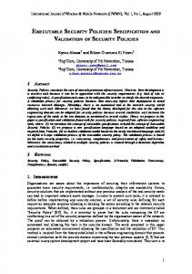
• Fingerprint of AppSlice • Command: activate / deactivate / restart AppSlice N aDa Content describes both AppSlice to be installed, with the corresponding policy as well as control data of P2P protocol. App Content Content distributed by the customer and control data of the customer protocols. App U ser Request Command sent from U ser to AppSlice. The format of this data has to be described in the NaDa user interface specification. App U ser Response Response sent from AppSlice to U I-User Interface (a module of the N odeM anagement). The format of this data has to be described in the NaDa user interface specification. N aDa Log (time stamp, action / measurement) produces a log entries for certain actions or measuring data. Actions and measurements are digitally signed by N odeM anagement relying on trusted time stamps. Log Request Command send from AppSlice to N odeM anagement to request (Monitoring) measurement data. N aDa Log is used when creating the request message. Log Response Response sent from N odeM anagement to AppSlice to forward information (e.g. Monitoring data) to AppSlice. N aDa Log is used when creating the response message. NaDa Primitives describe security relevant actions executed by NaDa Nodes, especially those relevant for communication between entities in different trust boundaries. The primitives will process certain protocols, and compute or access security relevant data. Figure 1 gives an overview of the security mechanisms realized by the these primitives. All stored data will be encrypted. Configuration of the NaDa Node and access of AppSlices to resources is controlled by the N odeM anagment. Communication between N aDaN odes is performed through overlay nets of the individual customers. Authentication and computation of keys for encryption in the overlay net is realized based on trusted P2P protocol presented in [7].
6
attestation Overlay Net configure Trust Anchor Key bound to Node State
Node Management
App Slice mandatory access control
encrypt Trusted P2P Trusted Data Store
encrypt with: Node_Store_Key
App Slice Configuration (rid) App_Slice_Policy Node_Store_Key
Node Store App Customer Data
Monitoring Data
Figure 1: Overview Node Security Architecture • N aDa Authentication (N aDaM anagement) Realizes the authentication and attestation described in [7] and provides a symmetric key for the encryption of communication between the participating entities. N aDa Authentication is also executed after reception of N aDa M eta Data e.g. for establish a encrypted connection to respond requests for measurement data. (N odeM anagement, 2nd • N aDa Get T icket node,N aDa Resource ID) realizes the the delivery of the trusted ticket (step 1 in MSC Figure 4 of the trusted P2P protocol) to N odeM anagement which can be used for communication with a second NaDa Node. • N ode Authentication (2nd node) Ticket obtained by N aDa Get T icket is used for authentication to second node. After attestation of the second node a symmetric key for the encryption of the communication between the two nodes is computed. “resource” used in MSC Figure 4 of the trusted P2P protocol addresses the corresponding overlay net. The policy (App Slice P olicy) for access to the overlay net has to be checked. • N aDa Connect(2nd entity,N aDa Resource ID) provides a symmetric key for encryption of communication. Depending of the type of 7
the 2nd entity only N aDa Authentication can be used if the 2nd entity resides in the the domain of the ISP. If another N aDaN ode is addressed a trusted ticket (N ode Authentication, N aDa Get T icket, N ode Authentication) has to be used. The information in which domain the entity resides is part of the NaDa Meta Data. • N aDa Register (N aDaM anagment) During the boot process N odeM anagement sends a registration message to to N aDaM anagement after authentication. N aDaM anagement responds with N aDa Conf igure to provide the node with the latest policy information. • N aDa Compute Key (N aDa Resource ID) computes key for storage encryption bound to current platform state and to the AppSlice determined by N aDa Resource ID. • N aDa Get Key (N aDa Resource ID) Get key for storage encryption bound to a certain AppSlice defined by N aDa Resource ID. • N ada Start P 2P (N aDa M eta Data,N aDa Resource ID) starts the P2P protocol to download N aDa Content described by N aDa M eta Data using the overlay net described by N aDa Resource ID. For every communication N aDa Connect has to be used to access the overlay net. Figure 2 explains the usage of the primitives to realize the overlay net used for communication between NaDa Nodes in the case of a centralized N aDa M anagment. ”rid” denotes the N aDa Resource ID labeling the overlay net. To hide the structure of the net N aDa N odes use the primitive N aDa Connect (which is not depicted in this diagramm) to establish a connection either with N aDa Authentication or with N ode Authentication. N ode Authentication uses the primitives N aDa Authentication and N aDa Get Key for getting the ticket to establish a connection to a second node.
8
2. NaDa_Get_Ticket(n2,rid)
ISP Site 2. NaDa_Get_Ticket(n1,rid)
NaDa_Management
1. NaDa_Authentication
1. NaDa_Authentication
rid3 rid2
Overlay Net
rid1
Node n2
Node n1 3. Node_Authentication(ticket)
Figure 2: Overlay Net Constitution
2.2
Putting Node into Service
The following steps describe the process of setting up a (new) STB into a NaDa platform. 1. Node reboot 2. Mutual authentication (N aDa Authentication) N aDaM anagement ↔ N odeM anagement 3. N aDa Register N odeM anagement → N aDaM anagement 4. In certain time intervals: N aDa Log (N aDa M easure Data) N odeM onitoring → N aDaM anagement to provide incentive mechanisms. 5. For all AppSlices N aDaM anagement performs the following actions. • Read App Slice P olicy(N aDa Resource ID) T rustedDataStore
from
• Disable traffic between new slice and all other slices not authorized by App Slice P olicy. • Configure overlay network according to the policy. • Assign encrypted block device N ode Store(N aDa Resource ID) to AppSlice. The key from the corresponding App Slice P olicy is used for encryption. • Boot AppSlice image. 9
2.3
App Slice Installation
The installation of a customer AppSlices is performed in the following steps: 1. N aDa M eta Data N aDaM anagement → N odeM anagement 2. N odeM anagement: N ada Start P 2P (N aDa M eta Data,N aDa M anagement ID). The following primitives are used between entities which are used in the DFDs for STRIDE analysis: • N aDa Authentication N aDaM anagement
N odeM anagement
↔
• N aDa Get T icket N odeM anagement ↔ N aDaM anagement • N ode Authentication N odeM anagement ↔ N odeM anagement • N aDa Content N odeM anagement ↔ N aDaM anagement • N aDa Content N odeM anagement ↔ N odeM anagement 3. After the slice is downloaded and the fingerprint ist checked N odeM anagement installs the slice: • Install Xen image • Create App Slice Conf iguration using policy delivered with AppSlice. • Disable traffic between new slice and all other slices not authorized by policy delivered with AppSlice. • Configure overlay network according to the policy. • Create key (bound to current state) for encryption of virtual block device (N odeStore) connected with the AppSlice and store key in the corresponding AppSliceConf iguration. • Store AppSliceConf iguration in T rustedDataStore tagged by N aDa Resource ID. • Assign block device (N odeStore) to AppSlice. • Boot slice. 4. App Log(App Slice fingerprint and policy) N odeM anagement → AppSlice
2.4
User Requests - Content Download
This scenario considers an (end) user requesting, through an user interface, access to a multimedia content stored on a NaDa STB which in turn may be located in her domicile. 10
1. AP P U ser Request (for content) U ser → U I(N odeM anagement) 2. AP P U ser Request U I(N odeM anagement) → AppSlice 3. N aDa Log(AP P U ser Request,time stamp) N odeM anagement → AppSlice: (signed by ISP) 4. AppSlice start P2P download (overlay net configured by N odeM anagement and N aDaM anagement otherwise transparent for N odeM anagement) 5. AP P U ser Response (AppSlice → U I(N aDaM anagement), if content, or certain part of content is downloaded) 6. AP P U ser Request U ser → U I(N odeM anagement): (e.g. Play) 7. AP P U ser Request U I(N odeM anagement) → AppSlice: Play)
(e.g.
8. N aDa Log(AP P U ser Request,time stamp) N odeM anagement → AppSlice: (signed by ISP) 9. N odeM anagement → AppSlice (in defined time intervals): N aDa Log(play,time stamp) signed by ISP 10. AP P U ser Request U ser → U I(N odeM anagement): (e.g. Stop) 11. AP P U ser Request U I(N odeM anagement) → AppSlice: Stop)
(e.g.
12. N aDa Log(AP P U ser Request,time stamp) N odeM anagement → AppSlice: (signed by ISP)
2.5
Monitoring as Support for Operation and Management Tasks
We consider the following three sub-scenarios in which the basic NaDa monitoring approach (see D1.1 [12], section 3.3) is deployed for the purpose of monitoring operational and management tasks. The rationale behind this rests on the fact that, ISPs may want to monitor all NaDa related network traffic and resource access/consumption in order to improve (or at least permanently guarantee) the operational stability and reliability of its platform. In such a context, there are interested in gathering STBs and slices related measurements (e.g. performance or anomalies) which are then made available to different stakeholders (e.g. content providers or eventually end users). As examples of operation and management tasks, we consider the following three use-cases: Firstly, the low-cost resources (re-) allocation in the 11
NaDa Platform, secondly the proactive and automatic detection of anomalies and load peaks, and finally the control of isolation between slices. These three perspectives on operation tasks pinpoint the relevance of monitoring as process which, on one hand provides inputs for the analysis and the improvement of the quality assurance (failure detection, maintenance, performance tuning) especially in video-on-demand context, and on the other hand helps reducing the network access cost. 2.5.1
Low-cost resources (re-) allocation
A persistent and global view of resources consumption and availability is fundamental for performing a flexible resources (e.g. available free slices, bandwidth or storage capability) allocation to content providers (i.e. their respective slices) in the NaDa platform. The allocation task in turn mainly relies on information collected by the NaDa monitoring processes. Here, a CP that operates slices in geographically distributed nodes, for instance across Europe is interested to know the state of health (e.g. running applications, security configuration and link utilization) of its nodes, characteristics of network paths between the nodes (e.g. reachability, delay, available bandwidth), and the current configuration/properties of its slices (e.g. memory, storage and computational utilization). Based on these information, the CP then identifies and analyzes the service popularity in a particular region (i.e. portion of the NaDa network). The gained knowledges allow CP to dynamically adapt its content distribution flow w.r.t end users preferences (e.g. based on service popularity), STB and slices configuration and actual SLA (which has been renegotiated in order for instance to allow CP to purchase more resources in the targeted NaDa network’s portion). Based on the collected Information, the pre-loading strategies considered in NaDa is specified and implemented. 2.5.2
Proactive and automatic detection of anomalies and load peaks
Beside the support of an efficient resources (re-) allocation, the observation of both network anomalies (e.g. indication of DDOS, failure of STB) and workload peaks is highly important for security, platform and resource management purposes. In this context, the required information are collected platform-wide, for instance (i) in a portion of the NaDa network or (ii) inside a hardware module (e.g. STB, residential gateway, DSL-Line Access Multiplexer, IP backbone). Here, a near real time notification and reporting of failure provides a significant level of flexibility, e.g. it allows the CP to automatically adapt to the new situation through the reconfiguration or isolation of both hardware and slices. The ISP is therefore interested to have both a historical and statistical view of platform’s behavior (inclusive anomalies,
12
CP related resources consumption or even illicit attempts to obtain more resources). 2.5.3
Isolation management
Since one central aspect of NaDa is to provide different CPs with the ability to carry their respective application slices on the same NaDa node, it is crucial from their point of view to rely on strict but flexible isolation of rivals applications. Considering the case in which for instance Warner Bros Entertainment1 and Vivendi2 have slices located on the same node. Here each provider is be allowed to access and collect any of their slices related properties (e.g. storage utilization). In absence of suitable, access control mechanisms and well-defined isolation between the different Monitoring flows, Warner Bros Entertainment may gain access to monitoring logs in which for instance the link utilization of the common host node is reported. This information does not only provide a view on the common node, at a given time, but also details for instance about services offered by Vivendi. Through an analysis of link utilization data, Warner Bros Entertainment can then gain access to business strategic information like statistics about services type and popularity, or the geographical region of interest of services offered by its competitor, Vivendi. Additionally monitoring processes furnish both NaDa and Node Management required inputs about a STB’s state, allocated resources and workload of each application slices. Based on such information, the management modules then enforces isolation between slices, i.e., prohibition of non authorized access to sensitive competitors’ data or to access platform’s resources.
3
Security Requirements and assumptions
The NaDa security architecture is based on several security requirements derived from the use cases. In the design of the security architecture different assumptions on security functionalities are done. In the following sections security requirements and assumptions relevant for the architecture are presented.
3.1
Security Requirements
The following high level security requirements for the NaDa architecture form the determining factor for the identification of threats and the appropriate mitigation techniques when the STRIDE analysis is conducted: 1 2
http://www.warnerbros.com/ http://www.vivendi.com/
13
• Isolation of App Slices corresponding to the policies defined by the customers must be ensured. Mandatory access control to network and to customer content has to be enforced according to these policies (Authentication, Authorization, Virtualization). • Customer content must be protected against manipulation and illegal access during network transfer and storage on NaDa nodes (Data Integrity, Confidentiality). • Customers must be enabled to set up secure accounting (Nonrepudiation services). • Nodes participating in the NaDa network must perform attestation, to report the integrity of the software running on these nodes (Platform Integrity). • Customer software should only be activated after checking the corresponding ISP certificate (Authenticity). • Correctness and Integrity of Monitoring Data: Requestor should have the confidence that the monitoring data reported are indeed what was monitored. The accuracy of the information reported has to be guarantee, since inaccurate data may lead to bad analysis results. Such guarantee may rely on one hand on the monitor’s ability to measure and report accurate data and on the other hand on the controller’s ability to verify authenticity and freshness of reported data. It may be assumed that unauthentic or unnecessary data are filtered by the controller before storage in the central MIB. • Confidentiality and Fine-grained Access Control: As NaDa considers outputs of monitoring processes as vital inputs for operational and management tasks (i.e. real-time performance analysis and troubleshooting) and such inputs as highly sensitive from the point of view of ISPs and CPs, confidentiality and access control methods have to be integrated within all phases of the monitoring process. The confidentiality has to be ensured from the early stage of the data collection up to the reporting and disclosure phases. The Collector orchestrating the data collection has to rely on encryption primitive or anonymization technique in order to allow a confidential reporting of sensitive monitoring data. The anonimization or encryption of such data has to be performed without loss of effectiveness and without a deterioration of quality and accuracy of collected data. A de-anonymisation or deencryption of stored data should only be possible for components and processes with appropriate (cryptographic) credentials. On the other hand, access control methods may rely on attributes (NaDa resource identifier or role), platform integrity or slice’s level of trust, ensuring 14
that only legitimate and authorized entities can access the collected measurements. Since the nodes are operated in different environments different security requirements are given for these nodes from the point of view of the ISP and of the Customer. From the point of view of the ISP it’s very important to avoid product recall or cost-intensive service for NaDa Nodes. Also the ISP must give guaranty that App Slices of different customers are strictly isolated. Thus it’s in the interest of the ISP to control installed App Slices and their updates. If for instance exploits enabling elevation of privileges for virtual images would be emerged it should not be possible for customers to install software using these exploits. Thus only App Slices signed by the ISP should be installed on NaDa Nodes in the field. The situation is somewhat different for NaDa Nodes under control of the customer. Trust boundaries between App Slices of different customers running on the same node do not exist in this case. Injection of content must be possible for these nodes. The main requirement is to restrict the access of the corresponding App Slices to the corresponding overlay net defined by the resource identifier of the APP Slices. Thus the integrity of the resource identifier of the corresponding App Slices has to be assured to prevent breaking out of the overlay net. To ensure this requirement the customer software of these specialized nodes also has to be certified by the ISP. Other solutions where uncertified hardware and software is utilized would require control possibilities for access to the overlay net of these entities. Various solutions, also depending from the contract between ISP and customer, would be possible but are out of scope of this analysis. The permission to install updates on App Slices for customers would exclude the possibility for the ISP to check the integrity of the App Slice software installed on the nodes. Thus arbitrary manipulation of App Slice software by users would be alleviated. A detailed discussion on the security requirements relevant for the NaDa scenarios can be found in D1.1 [12] [8] [3] [2] and [6].
3.2
Security Assumptions
For the scenarios presented in section 2 following assumptions apply: • Sensitive data, like private ISP keys, App Slice fingerprints, and App slice images to be delivered will be protected by the ISP. The corresponding measures will not be part of this threat analysis. • Manipulation of the software e.g. due to a buffer overflow can’t be prevented.
15
• Customer IDs and App Slice IDs must be part of the tickets computed by the trusted peer to peer protocol, to provide addressing of Node Management and App Slices and also for the configuration of the overlay network. This address information will be stored in “N aDa Resource ID” used in MSC Figure 4 (Step 1, as “resource”) of the trusted peer to peer protocol defined in [7]. NaDa Resource is defined as follows: N aDa Resource := (N ode M anagement ID, nil) | AP P Slice ID AP P Slice ID := (Customer ID, AP P ID) • During boot process of a NaDa Node the internet connection to the ISP must be available, to register the node and for time synchronization. • Trusted Platform Administrator: The designed isolation administrator and NaDa platform manager is trusted to access and process sensible platform and applications’ metering data. Those managers act in accordance with their costumers’ security preferences. • Correct hardware: The underlying hardware (e.g. TPM, CPU-chip, I/O and storage devices, etc.) behaves in accordance with the specifications and standards. • Trusted TCB and reliable Isolation: The virtualization engines as well as other components of the trusted computing base of the NaDa monitoring architecture are correct and behave as specified. • No advanced physical attacks: We have assumed that the underlying hardware included in the NaDa Monitoring Architecture are resilient against such type of attacks.
4
High level model
The high level model for the NaDa architecture is composed of the node architecture including the communication of the interactions between the respective components on the one hand and the security model for the monitoring modules. The monitoring modules are situated and operated based on the node architecture as an independent service. In the following chapters these two models are presented.
4.1
Node architecture model and interactions
As presented in [8][12][13] the architecture of the NaDa infrastructure is based on the P2P paradigm allowing for a highly available infrastructure by 16
Figure 3: High level architecture for the distribution of content distributing some of the core functionalities into the nodes installed. The resulting high level architecture is depicted in Figure 3 and consists of the node and its supporting infrastructure. Mainly two players’ components are shown there. The customer is represented by its slice and the corresponding centralized application tracker as well as its support by the customers Identity Provider and the store of content offered by the customer. In Figure 3 only one customer is shown for the sake of simplicity. Additional customers are duplicating the customer related components.
4.2
Security Mechanisms for the NaDa Monitoring Architecture
This section describes a secure monitoring infrastructure using trusted computing and virtualization concepts. Both concepts enable trustworthy generation and storage of monitoring data. The further disclosure of such sensitive data is governed in the proposed architecture by fine grained access control policies. In order to provide the fine grained access control required for a large scale use of NaDa, we have integrated XACML [9] components into the NaDa basic monitoring architecture. The new security mechanisms extend the architectural view on the basic NaDa Monitoring Architecture (see D1.1 [12][13] and [8]). 4.2.1
Internal Security and Access Control Mechanisms
The proposed mechanisms ensuring STB internals data protection leverage the isolation techniques already introduced (see D1.1 [12][13]) and allow fine grained access control to monitoring measurements. Such measurements generated during the active monitoring of a STB as well as during the passive monitoring of slices running in that STB are temporarily stored in a local repository which in turn is protected by the means of secure storage (NADA 17
Figure 4: High level architecture for the measurement security primitive NaDa Compute Key and NaDa Get Key as defined in section 5.1.3). Previously to their storage the monitoring data are signed by the Node Management relying on trusted time stamps as specified by the NaDa Log primitive 5.1.3. Any request from a slice for internal measurements is handled by the Node Management, which is internally responsible to authenticate request for local measurements and to restrict access to locally stored monitoring data. The request and access to monitoring data are performed with respect to authentication, authorization (section 4.2.2) and confidential disclosure of monitoring data. Figure 5 depicts the relevant security components and modules of the STB focusing on the protection of measurements locally stored. In the following a description of those components and modules as well as their respective contributions to secure the internal monitoring process is provided. The first two modules (monitor and local MIB) basically extents the functions of the Node Monitoring initially introduced in D1.1 [12][13] section 3.1. Monitor The monitor deployed in each NaDa node (STB) is responsible for triggering active measurements from this node and for passively monitoring slices running in the node. It captures several types of node and slices related information, protects them according to (NaDa and slices) policies and delivers them to monitoring service. Relying on traditional tools (e.g. CACTI [4], Nagios [1] or Munin [11]) which in turn use standards like PRSCTP or IPFIX, the monitor initiates the collection of host node, network characteristics as well as slices related metering data.
18
COMM API
COMM API
Figure 5: Node Intermal Security Components Local MIB All STB’s and local slices’ measured properties are first stored in a local MIB. The content of each local MIB is then transferred in the global MIB. The split between local and global MIB as well as the periodical update of the gloabl MIB can be considered as a step towards a good compromise between the need for fresh platform measurements and the monitoring overhead. The secure storage by means of integrity and confidentiality relies on primitive for storage encryption bound to the STB’ configuration or to slice’s state. This process benefits from the combined potentials of TPM and virtualization as specified in D1.1 [12][13]. VMM VMM primarily provides an abstraction to the underlying hardware resources of the host STB, and defines an isolated execution environment for each stored slices. In order to perform the isolation between application slices running on the same physical NaDa box, the VMM defines a module which is build as policy enforcement and policy decision point for a wide range of low-level security policies. For instance this module may include pre-defined policies that specify which slices are allowed to communicate or share resources together and which security requirements the exchanged messages must satisfy. The specification and enforcement of highlevel (finer-grained) access control requirements for the temporarily stored local measurements will be handled by the node monitoring. TPM We refer to the TPM as hardware-based trust anchor inside the STB (see D1.1 [12][13]). The overall security mechanisms for the NaDa Monitoring make use of its potential for several purposes e.g., for a trustworthy 19
1Request local Measurements COMM API
COMM API
9- Local Measurements
COMM API 8- Data
2- Request Evaluation 7- Query 3- Decision Request
6- Decision
4- Policy Request
Context
5- Policy Response
Figure 6: Internals Monitoring Process collection of boxes and slices properties, and for ensuring a continuous chain of trust/integrity up to the slices, and 4.2.2
Internal Monitoring Process
The workflow for requesting internal monitoring data (e.g. performance of host box or characteristics of co-located slices) is depicted in Figure 6 and described as follows: • First of all, a slice S1 requests measurement data (Log Request and Log Response in 5.1.3). Upon receiving this request, the Node Management applying the isolation policy also performs internal access control to the local MIB. This involves evaluating the slice’s request by means of authentication (cf. relying on slice’s unique identifier APP Slice ID). As result of this step, Node Management which is designed as Policy Enforcement Point (PEP) validates S1’s level of trust and allows the request to be forwarded (asking for an authorization decision) to the Node Monitoring (steps 1-3). • Node Monitoring designed as Policy Decision Point (PDP) then performs access authorization providing the required finer granularity of 20
access control. This involves requesting policy rules and obligations from the policy repository. Based on these policies and other security context (e.g. trust level of slice or current state of the STB) the Node Monitoring generates an authorization (permit or deny) decision which is then transferred to the Node Management(PEP) (steps 4-6). • Finally, the PDP’s decision is enforced by the PEP (i.e. Node Management) which unseals (relying on NaDa Get Key) the local MIB from the secure storage, queries and transfers the targeted measurements information to S1 (steps 7-9). 4.2.3
External Security Mechanisms
As shown in Figure 7, this section considers mechanisms to enforce security requirements of a central component of the NaDa Monitoring Architecture: The monitoring server. The resulting security methods aim at providing the primitive to protect the integrity and confidentiality of the monitoring data from the reporting by STBs up to their storage in the global MIB and their dissemination by the Monitoring Server. As result we extend the functionalities of monitoring server’s main component as defined in the following paragraphs. Secure Reporting In our extension, Node Monitoring reports the monitoring measurements as encrypted data. The secure reporting by means of encryption and digital signature mainly relies on NaDa Connect primitive for building the encrypted communication channel between monitoring in STB and Controller in monitoring server. The controller module of the monitoring server on the other hand decrypts the received measurement values, performs the orchestration and stores the plain-text data in the MIB. Previously to the encryption and decryption, both entities performed a bidirectional authentication (using the Node Authentication primitive) as well as the negotiation of the symmetric key used to encrypt or decrypt the reported measurement. Global Access Control Mechanisms The global access control mechanisms tailor the XACML Framework [9]to our purpose. The resulted architecture is depicted in Figure 7 and mainly includes four components: Controller, MIB, Exporter which is design as PEP and PDP, and a Policy Manager which is designed to be in charge of the security policies governing the access to the MIB. Although Figure 7 depicts a centralized access control approach describing the four components as part of a single central entity, we stress that these components can also be physically distributed throughout the NaDa
21
Crypto Services Interface
Meas. Query/ Response
Update
Pol. Query/ Response
Request Measurements Encrypted and Authentic Measurements
NaDa Management or Application Controller
Monitor
Measurements Request with privileges attributes and sec. Credentials Measurements Response
Figure 7: Extended NaDa Monitoring Service Architecture network. The following subparagraphs detail the functionalities of each of these components. Controller Besides its ability to require measurements from different STB (i.e. monitors) and orchestrate all the measurement collection the Controller can also use en-/decryption primitives (NaDa Compute Key and NaDa Get Key) to store the collected measurements as clear text in the global MIB. The required guarantee that the monitoring server interacts with the correct STB (i.e. the box is trustworthy and belong to the correct ISP domain) is provided when relying on NaDa Authentication and Node Authentication primitive (see 5.1.3). (Global) MIB This repository stores all STB’ and Network measurements. These data are protected by means of encrypted storage which is bound to trust state and configuration of the monitoring server. We rely for this purpose on a set of functions specified by the TCG i.e., integrity reporting and attestation, (un-) sealing and (un-) binding functions among others (see D1.1 [12][13] Section 2.3.2). Thus, the MIB can only be available if no change has been detected in the configuration of the monitoring server (i.e. the server and its measurement information data base have not been subject of security attacks, and the integrity of the stored monitoring data remains intact). Exporter We extent the Exporter Module with a set of entities and functional components that allow authorization decisions to be made and 22
enforced based on security credentials (e.g. certified requester’s attributes) and in accordance to access control policies. In the following an overview of the PEP and PDP roles of the Exporter is presented. • Policy Enforcement Point (PEP) - The Exporter is the entity where the external query for monitoring data arrive. It authenticates the queries and enforces the decision made by PDP’s decision. The PEP must be able to intercept any request, for monitoring data, between Application Controller or NaDa Management and the Exporter. It should be noted that, the technical implementation of the PEP must be performed such that the PEP cannot be bypassed in order to access the protected MIB. • Policy Decision Point (PDP) - As PDP the Exporter makes decisions to authorize access. The PDP uses the access control policies from the PAP as well as additional information (context information, e.g. slice’s trust level or server current configuration) in order to evaluates policies and make a decision to authorize access to the local MIB. The authorization decision process also relies on other components like for instance the context handler, which are for simplicity reasons not shown in Figure 7. As part of controlling access to the MIB, the Exporter also performs request evaluation/ authentication as already pointed out in the basic Monitoring architecture (see D1.1 [12][13]). It therefore integrates the authentication function and primitives provided by the cryptographic module (see below). Policy Manager This entity is designed as XACML Policy Administration Point (PAP) which is basically the entity that creates storages and manages all access control policies used by the PDP (i.e. Exporter). These policies consist of decision rules, conditions, and other constraints for accessing the data stored in the global MIB. The policy manager specifies access control policies with respect to the level of confidentiality required for monitoring information (neutral or sensitive), and security affiliation and credentials of the requester. Furthermore, the policy manager specifies conditions and obligations for access control policies (e.g. log any request and access to MIB for accountability purposes) allowing a deployment in a vast range of use-cases. This will provide the basis for future security auditing. Cryptographic Module This module includes a TPM and other cryptographic and key management primitives. It therefore provides, validates, and maintains the cryptographic keys which are used by the data protection mechanisms enforced by the Exporter. For these purposes, the interaction with an external Public Key Infrastructure (PKI) is considered. 23
Secure Measurement Collection (Report)
Secure Export (Global Access Control)
Crypto Services Interface
6- Meas. Query/ Response IV-Update
5- Pol. Query/ Response
III- Authentication, decryption and orchestration
I- Request Measurements II- Encrypted and Authentic Measurements
2- Request Evaluation
NaDa Management or Application Controller
Monitor
1- Measurements Request with privileges attributes and security credentials 7- Measurements Response
Figure 8: External Monitoring Process In addition it provides along with the authentication primitive defined in section 5.1.3. the required inputs for trust negotiation between access requester and monitoring server, especially when the monitoring server needs slice to provide authentic credentials/attributes for authorization decision. 4.2.4
External Monitoring Process
This process is relevant for Application Controller and NaDa Management which need information related to the performance/status of any NaDa box or related to (owned) slices stored somewhere on the NaDa platform. Figure 8 shows the integration of security mechanisms described above and differentiate between two subprocesses: Secure measurement collection and secure measurement export. Secure Measurement Collection (Report) The steps included in this subprocess are depicted in the left Block of Figure 8. • In the first step, the Monitoring Server (through its Controller module) contacts the Monitor inside a STB and request measurements (Log Request)(step I). • In order to guarantee authenticity and confidentiality, both Controller and Monitor engage in a bidirectional authentication (Node Authentication) and negotiate a symmetric key for encrypted communication (NaDa Connect). The monitor then transmits STB’s
24
measurements (Log Response) as ciphertext to the Collector (steps II, III). • After receiving encrypted measurements, the Controller uses its part of the symmetric key to decrypt the ciphertext. Afterwards it orchestrates all data collection, unseals (NaDa Get Key) and updates the MIB (steps IV, V). Secure Measurement Export (Global Access Control) The right block of Figure 8 shows the different steps which composed the Secure Measurement Export. • At the beginning the NaDa Management or an instance of an Application Controller sends a measurement request (Log Request) to the Exporter, along with its security credentials (step 1). • The Exporter funding as PEP evaluates the request by means of authentication (Node Authentication) and retrieves authorization rules from unsealed Policy Repository (step 2, 3). • Based on these rules and addition information (e.g. current configuration) the Exporter designed as PDP makes a deny/allow decision. In case it authorizes the access, the targeted measurements are queried from unsealed MIB and transferred (Log Response) to the NaDa Management/ Application Controller (step 4, 5).
5
Threat Models
This Deliverable (D3.2) defines the NaDa security architecture based on the STRIDE methodology given by Microsoft. In the respective section STRIDE is introduced and the architecture is given. As a mean to verify the design a second approach is introduced using an abstract functional system model. Section 5.2 introduces this approach and provides first results later used in the evaluation as part of D3.4 [14].
5.1
STRIDE methodology and architecture
A threat model of the NaDa architecture, based on STRIDE, a methodology introduced by Howard and Lipner in [5], will be presented. STRIDE is an acronym for Spoofing, Tampering, Repudiation, Information Disclosure, Denial of Service, and Elevation of Privilege (EoP). Two use scenarios build the base of the threat model. Data flow diagrams (DFDs) will be created for the corresponding use cases. All primitives and the corresponding elements of the NaDa architecture are included in the DFDs. For every element of a DFD applicable threats will be assigned to 25
these elements, according to the stated high level security requirements for the NaDa architecture. In the next step the threat mitigation techniques of the NaDa architecture will be assigned to the DFD elements and their corresponding threats. Finally it can be checked, whether there is a countermeasure for every expected threat assigned to the DFD. The tables with the measurement assignment can be used as a checklist for the implementation and code review of the security mechanisms of the NaDa components. 5.1.1
Differences to STRIDE Methodology
Table 1 shows the mapping of threats to DFD elements proposed in [5]. This mapping was inappropriate for several reasons: • The abstraction level for processes required different measures against spoofing depending on the corresponding data flow entities. So spoofing was also assigned to data flows. • Also repudiation was assigned to data flows in opposite to the standard way of proceeding, because all actions related to this threat could be mapped exactly to one data flow entity. Repudiation was not considered for external entities and processes. For data stores and processes tempering was checked for entities involved in the corresponding data flow. Figure 9 shows the modified workflow for the performed STRIDE analysis. Use Scenarios were developed on base of the high level architecture described in [7].
26
High Level Architecture
High Level Requirements
Use Scenarios
Counter Measures
STRIDE Default Threats
DFDs
Threat Mitigation
Checklists
Input for Formal Methods ?
Code Review
Figure 9: Workflow for modified STRIDE Analysis
Table 1: Mapping STRIDE Threats to DFD Element Types DFD Element Type S T R I D External Entity X X Data Flow Data Store Process 5.1.2
X
X X X
X X
X X X
X X X
E
X
External Dependencies
Components of the system running on NaDa nodes • A TPM crypto processor will be used on NaDa nodes. • Ubuntu hypervisor running Xen will be used as virtualization technology to run NaDa management and App Slices. • The sHype [15] hypervisor security architecture will be used to control information flow between App Slices sharing a single NaDa Node. 27
• Authentication and Attestation, thus the realization of the overlay network, and the NaDa P2P protocol will be based on an implementation of a trusted P2P protocol described in [7]. • Beside his own implementation of a P2P protocol the customer has to implement an interface to be able to receive commands from Node Management, and to deliver AP P Content: – AP P U ser Request for user interaction – AP P Log to receive accounting information from Node Management 5.1.3
DFDs
All primitives and data exchanged between NaDa components are included in the following data flow diagrams (DFD). Data flows not going through trust boundaries are depicted with dashed arrows. For all other data flows trust boundaries are crossed. Trust boundaries exist for data flows between components with different privileges. E.g. an App Slice has lower privileges than Node Management. To achieve better clarity in Figure 10 the DFD is divided into two subdiagramms.
28
P2:NaDa Management
F1.1:NaDa_Register
F1.2:NaDa_Meta_Data
D3:Trusted Data Store
F2.1:NaDa_Authentication
F2.2:NaDa_Get_Ticket
F6.1:App_Slice_Data
Node Management P1.1:Node Management
F0:NaDa_Policy
F2.3:Node_Authentication
P1.3:UI (Node Management)
F5.3:Log_Response
P1.1__2:Node Management_2
F5.2:Log_Request
P3:APP Slice
D1:NaDa Store
F7:NaDa Content
P2:NaDa Management
P3:APP Slice
F3.1:NaDa Content
F8:App_Content F3.4:App_Content
P1.1:Node Management
D2:Node Store
F3.2:App_Content F3.3:NaDa Content
F3.5:App_Content F5.1:APP_User_Request
P1.3:UI (Node Management)
F4.2:App_Content
Node 2 P1.1__2:Node Management_2
E1:User
F9:App_Content
P3__2:APP Slice_2
Figure 10: DFDs Table 2: DFD Elements External Entities Processes
E1 P1.1 P1.2 P1.3 P2
User Node Management Node Monitoring UI (Node Management) NaDa Management
29
F4.1:APP_User_Request
Data Stores
Data Flows
P3 D1 D2 D3 F0 F1.1 F1.2 F2.1 F2.2 F2.3 F3.1 F3.2 F3.3 F3.4 F3.5 F4.1 F4.2 F5.1 F5.2 F5.3 F6.1 F7 F8 F9
APP Slice NaDa Store Node Store Trusted Data Store NaDa Policy P1.1 → P1.3 NaDa Register P1.1 → P2 NaDa Meta Data P2 → P1.1 NaDa Authentication P2 ↔ P1.1 NaDa Get Ticket P2 ↔ P1.1 Node Authentication P1.1 ↔ P1.1 2 NaDa Content P2 ↔ P1.1 App Content P1.1 ↔ P1.1 2 NaDa Content P1.1 ↔ P1.1 2 App Content P3 ↔ D2 App Content P3 → P1.3 APP User Request E1 → P1.3 App Content P1.3 → E1 APP User Request P1.3 → P3 Log Request P3 → P1.1 Log Response P1.1 → P3 App Slice Data D3 ↔ P1.1 NaDa Content D1 → P2 App Content P3 ↔ P1.1 App Content P1.1 2 ↔ P3 2
Table 3: Threats to the System Threat Type Spoofing
Tampering
Repudiation Information Disclosure
EoP
DFD Item Number External Entities: E1 Processes: P1.1, P1.2, P1.3, P2, P3 Data Flows: F0, F1.1, F1.2, F2.1, F2.2, F2.3, F3.1, F3.2, F3.3, F3.4, F3.5, F4.1, F4.2, F5.1, F5.2, F5.3, F7, F8 Processes: P1.1, P1.2, P1.3, P2, P3 Data Stores: D1, D2, D3 Data Flows: F0, F1.1, F1.2, F2.1, F2.2, F2.3, F3.1, F3.2, F3.3, F3.4, F3.5, F4.1, F4.2, F5.1, F5.2, F5.3, F6.1, F7, F8, F9 Data Flows: F3.4, F3.5, F4.1, F4.2, F5.1, F5.2, F5.3, F8 Processes: P1.1, P1.2, P1.3, P2, P3 Data Stores: D1, D2, D3 Data Flows: F0, F1.1, F1.2, F2.1, F2.2, F2.3, F3.1, F3.2, F3.3, F3.4, F3.5, F4.1, F4.2, F5.1, F5.2, F5.3, F6.1, F7, F8, F9 Processes: P3
30
Plan Mitigations Table 4 lists high level mitigation techniques proposed in [7]: Table 4: Threat Typ Spoofing Tampering Repudiation Information disclosure DoS EoP
High Level Mitigation Techniques Mitigation Technique Authentication Integrity Non-repudiation services Confidentiality Availability Authorization
In [8] mitigation techniques provided by the NaDa platform were presented in textual form. In the next step the measures described in this paper were divided into “atomic” measures. This partitioning allows to assign single measures to STRIDE threats and in the next step to the table where DFD elements are assigned to these steps. Isolation of App slices and the access control to physical resources will be assured by virtualization. Virtualization is not listed as specific mitigation technique in the following table. Only measures necessary to control interfaces of the virtual images and to enforce the NaDa policies will be listed. Also Trusted Platform Module will not be listed as an “atomic” mitigation technique. Table 5: NaDa Measures Measures M0.1 ISP responsibility M0.2 Customer responsibility M0.3 ** No measure ** M1 Mandatory access control in hypervisor (sHype) M2 Firewall rules running in the NaDa nodes M3 Trusted ticket for access to overlay net M4.0 Create signed log entry with trusted timestamp M4.1 Send log entry for User Action to APP slice M4.2 Write log entry for Action to Trusted Data Store M4.3 Send log entry for Action to NaDa Management M5 Check fingerprint of APP Slice M6.1 Trusted Boot, initialize measuring data for loaded code. M6.2 Initialize Trusted Data Store M6.3 Initialize Node Store M7.1 Encrypt Trusted Data Store M7.2 Encrypt Node Stores M8 ISP Certificate M9 Remote node attestation 31
Table 5: NaDa Measures Measures M10 Mutual authentication M11 Meta data signed by ISP M12 Encryption of channel M13 Encryption Overlay Net M14 App Identifier displayed by ISP M15 Data stored in Trusted Data Store M16 e.g. HDMI digital content protection M17 e.g. Digital watermarking M18 Don’t store data worthy to be protected in this entity M19 Correct assignment of Resource ID to AppSlice M1 sHype stands for secure hypervisor. sHype is a hypervisor security architecture developed by IBM Research available for XEN virtualization. sHype supports policy-based information flow control for virtual machines. Two standard policies ”Chinese Wall” and ”Simple Type Enforcement” are available. It’s possible to define coalitions which can share resources. sHype types are used in these policies and define the granularity for App Slice coalitions and the available resources (App Stores). NaDa policies must define the mapping of NaDa Resource IDs to these types. For mandatory access control to App Stores simple type enforcement policy will be used (App Slices can use resources with equal types). So according to customer policies isolation from resources of other customers can be enforced, and the sharing of resources between different App Slices can be permitted. The policy defined by the customer has to be verified by the ISP. Only certified policies will be used to configure access rights of App slices. M2 Virtualization is used to isolate App Slices according to policies defined by the customers. The network connections of APP Slices are critical parts of the architecture respective to breaking these policies. A standard framework (e.g. iptables) has to be used to control network traffic between different App Slices by the privileged domain of the NaDa Node. The default firewall rules have to enforce strict separation of App Slices. Customer policies allowing communication of different App Slices on the same node have to be certified by the ISP. M3 There are two types of ”overlay nets” . The overlay net which is used to exchange N ada Content ( App Slices, updates) and the overlay nets for customer applications. Beside the IP addresses the NaDa resource identifier (see 2.1) is used to address entities in the NaDa Network and to define the structure of the overlay net. Only one specific resource identifier is used to address NaDa entities in the network. 32
Thus there is one NaDa specific overlay net which can be used by all NaDa entities for maintenance purposes. The NaDa resource identifier must be different from customer resource identifiers. The customer defines the policy which other applications (identified by their N aDa Resource ID) can use a certain resource (App Slice). This policy is delivered to NaDa nodes together with App Slice images. Thus this policy implicitly defines the structure of the overlay net and also has to be verified and certified by the ISP before installation. Base for the communication in the overlay net is the “trusted ticket” computed in the last step of the trusted P2P protocol presented in [7]. Additional to the verification of the ticket the policy for accessing NaDa resources has to be checked with the NaDa Resource ID which is part of the ticket. A symetric key for encryption can be computed after the ticket is delivered to the addressed node and the remote attestation of this node is performed successfully. M4.0 A non-repudiation service must exist to produce trusted log data with timestamps. Trusted log would not possible without performing time synchronization during boot process. Time synchronization must be repeated in certain time intervals to avoid inaccuracies. Log entries have to be signed with a key derived from the root of trust of the NaDa Node. M4.1 Log entries collected by the ISP have to be created according to M4.0. Depending on log policy. The log entries must be written to Trusted Data Store or have to be sent to NaDa Monitoring. M4.2, M4.3 Log entries collected by the ISP have to be created according to M4.0. Depending on log policy The log entries must be written to Trusted Data Store or have to be sent to NaDa Monitoring. M5 The fingerprints of App Slices have to be checked before installation. The fingerprint is part of the meta file signed by ISP which describes the NaDa Content to be downloaded. M6.1 Every code running on a NaDa Node has to be measured before execution. (for measurement of App Slice code see M5). NaDa Nodes have to be equipped with platform firmware that must be implicitly trusted. This firmware has to initialize the root of trust for reporting (RTR), which accumulates measuring data for loaded code. For other entities of the NaDa architecture it must be possible to check the attestation for this measuring data to verify the integrity of the loaded code. M6.2 The key for encryption of the Trusted Data Store has to be computed on the node and must be bound to the attested state of the NaDa Node. 33
Thus there must exist a root of trust for storage and the possibility to bind usage of stored data do measuring data computed in M6.1. Usage of this key is only permitted in an attested state. M6.3 A key for encryption of the Node Store has to be computed. This key has to be stored in Trusted Data Store under the Resource ID of the corresponding App Slice. So this key is implicitly bound to an attested state of the platform. Access to Node Store is only possible with attested software. M7.1 Trusted data store has to be encrypted to guarantee integrity of stored policy data, NaDa Management data, and log data. M7.2 Data of Node Stores assigned to certain App Slices has to be encrypted to prevent illegal access to content and to prevent manipulation of customer content. M8 The ISP certificate is part of the NaDa Management software installed on the NaDa node before delivery in a trustworthy environment. M9 Attestation of the actual node configuration and the actual firmware version to remote parties must be possible. Measuring data computed in M6.1 will be used for remote attestation. M10 Mutual authentication between Node Management and NaDa Management must be provided. In the case of centralized NaDa Management the protocol described in MSC Figure 2 of the trusted P2P protocol is used. Parts of the NaDa Management could run distributed. In this case the protocol from MSC Figure 3 must be used. Base for the mutual authentication are the remote attestation capabilities of the nodes (M9) and the ISP certificate used to verify messages from the centralized NaDa Management (M8). A symmetric key for encryption will be exchanged when this protocol is used. M11 The metafile describing NaDa specific content has to be signed by ISP tu guarantee integrity of this content. M12 Network traffic between centralized NaDa Management and NaDa Nodes has to be encrypted. The symmetric key computed in M9 is used for encryption. M13 Network traffic between NaDa Nodes has to be encrypted. The symmetric key computed in M3 is used for encryption. M14 To avoid spoofing of the user interface for certain App Slices the ISP should ensure that the identity of the current content provider is presented for the user, beside the presentation of the data provided by the content provider. 34
M15 All data used by NaDa Management and NaDa Monitoring has to be stored in Trusted Data Store, to ensure integrity of this data. So access to data is possible for previously defined software only (M6.1, M6.2). M16 For content delivery digital content protection (e.g. HDMI) could be used. M17 NaDa will provide capability for digital watermarking in the standard libraries of App Slices for the content providers. M18 If a entity is not encrypted do not store secret data in this entity. M19 Correct assignment of N aDa Resource IDs to App Slices and to physical resources is essential for correct isolation of App Slices. Parts of the software performing this assignment should be reviewed, or if possible investigated using formal methods. All tables presented in this paper are generated from YAML files (http//www.yaml.org). YAML is a human friendly data serialization standard for many programming languages. This offers several opportunities: • Data could be used to generate specifications for model checking. • Data could be used for generation of check-lists. • Data could be used for policy generation. Also dependencies between single measures are defined in the YAML files (see Figure 11).
35
M4.0:Create signed log entry with trusted timestamp
M4.2:Write log entry for Action to Trusted Data Store
M4.3:Send log entry for Action to NaDa Management
M4.1:Send log entry for User Action to APP slice
M6.1:Trusted Boot, initialize measuring data for loaded code.
M8:ISP Certificate
M9:Remote node attestation
M6.2:Initialize Trusted Data Store
M10:Mutual authentication
M11:Meta data signed by ISP
M12:Encryption of channel
M7.1:Encrypt Trusted Data Store
M3:Trusted ticket for access to overlay net
M6.3:Initialize Node Store
M13:Encryption Overlay Net
M7.2:Encrypt Node Stores
Figure 11: Measure Dependency Table 6 assigns mitigation techniques provided by the NaDa platform to the high level mitigation table 4. techniques proposed in [5]. Table 6: NaDa Mitigation Techniques Mitigation Technique and Measures Authentication (Spoofing) M0.2 Customer responsibility M8 ISP Certificate M2 Firewall rules running in the NaDa nodes M3 Trusted ticket for access to overlay net M9 Remote node attestation M14 App Identifier displayed by ISP M10 Mutual authentication - F2.1 provides M10 M12 Encryption of channel M13 Encryption Overlay Net M1 Mandatory access control in hypervisor (sHype) M19 Correct assignment of Resource ID to AppSlice M0.3 ** No measure ** M0.1 ISP responsibility
36
Table 6: NaDa Mitigation Techniques Mitigation Technique and Measures Integrity (Tampering) M0.1 ISP responsibility M7.2 Encrypt Node Stores M7.1 Encrypt Trusted Data Store M6.1 Trusted Boot, initialize measuring data for loaded code. M5 Check fingerprint of APP Slice M9 Remote node attestation M10 Mutual authentication - F2.1 provides M10 M12 Encryption of channel M11 Meta data signed by ISP - F2.3 provides M11 M13 Encryption Overlay Net M3 Trusted ticket for access to overlay net M1 Mandatory access control in hypervisor (sHype) M19 Correct assignment of Resource ID to AppSlice M0.3 ** No measure ** M4.0 Create signed log entry with trusted timestamp M2 Firewall rules running in the NaDa nodes Non repudiaton service (Repudiation) M17 e.g. Digital watermarking M4.1 Send log entry for User Action to APP slice M4.0 Create signed log entry with trusted timestamp M4.3 Send log entry for Action to NaDa Management Confidentiality (Information Disclosure) M7.2 Encrypt Node Stores M7.1 Encrypt Trusted Data Store M18 Don’t store data worthy to be protected in this entity M0.1 ISP responsibility M0.2 Customer responsibility M12 Encryption of channel M10 Mutual authentication - F2.1 provides M10 M13 Encryption Overlay Net M2 Firewall rules running in the NaDa nodes M19 Correct assignment of Resource ID to AppSlice M16 e.g. HDMI digital content protection Authorization (EoP) M1 Mandatory access control in hypervisor (sHype) M2 Firewall rules running in the NaDa nodes
37
Table 6: NaDa Mitigation Techniques Mitigation Technique and Measures M3 Trusted ticket for access to overlay net
Table 7: Assigned Countermeasures Threat Type Spoofing
DFD Item Number External Entities: E1: User - M0.2 : Customer responsibility Processes: P1.1: Node Management - M9 : Remote node attestation - M6.1 : Trusted Boot, initialize measuring data for loaded code. - M3 : Trusted ticket for access to overlay net - M10 : Mutual authentication - M8 : ISP Certificate - M9 : Remote node attestation - M6.1 : Trusted Boot, initialize measuring data for loaded code. P1.2: Node Monitoring P1.3: UI (Node Management) - M14 : App Identifier displayed by ISP P2: NaDa Management - M8 : ISP Certificate P3: APP Slice - M2 : Firewall rules running in the NaDa nodes - M3 : Trusted ticket for access to overlay net - M10 : Mutual authentication - M8 : ISP Certificate - M9 : Remote node attestation - M6.1 : Trusted Boot, initialize measuring data for loaded code. Data Flows: F1.1 - NaDa Register: Node Management → NaDa Management - M10 : Mutual authentication - M8 : ISP Certificate - M9 : Remote node attestation - M6.1 : Trusted Boot, initialize measuring data for loaded code. F1.2 - NaDa Meta Data: NaDa Management → Node Management - M10 : Mutual authentication - M8 : ISP Certificate - M9 : Remote node attestation - M6.1 : Trusted Boot, initialize measuring data for loaded code. F2.1 - NaDa Authentication: NaDa Management ↔ Node Management 38
Table 7: Assigned Countermeasures Threat Type
DFD Item Number - M8 : ISP Certificate - M9 : Remote node attestation - M6.1 : Trusted Boot, initialize measuring data for loaded code. F2.2 - NaDa Get Ticket: NaDa Management ↔ Node Management - M10 : Mutual authentication - M8 : ISP Certificate - M9 : Remote node attestation - M6.1 : Trusted Boot, initialize measuring data for loaded code. F2.3 - Node Authentication: Node Management ↔ Node Management 2 - M3 : Trusted ticket for access to overlay net - M10 : Mutual authentication - M8 : ISP Certificate - M9 : Remote node attestation - M6.1 : Trusted Boot, initialize measuring data for loaded code. F3.1 - NaDa Content: NaDa Management ↔ Node Management - M12 : Encryption of channel - M10 : Mutual authentication - M8 : ISP Certificate - M9 : Remote node attestation - M6.1 : Trusted Boot, initialize measuring data for loaded code. F3.2 - App Content: Node Management ↔ Node Management 2 - M3 : Trusted ticket for access to overlay net - M10 : Mutual authentication - M8 : ISP Certificate - M9 : Remote node attestation - M6.1 : Trusted Boot, initialize measuring data for loaded code. - M3 : Trusted ticket for access to overlay net - M10 : Mutual authentication - M8 : ISP Certificate - M9 : Remote node attestation - M6.1 : Trusted Boot, initialize measuring data for loaded code. F3.3 - NaDa Content: Node Management ↔ Node Management 2 - M13 : Encryption Overlay Net - M3 : Trusted ticket for access to overlay net - M10 : Mutual authentication - M8 : ISP Certificate - M9 : Remote node attestation - M6.1 : Trusted Boot, initialize measuring data for loaded code. F3.4 - App Content: APP Slice ↔ Node Store - M1 : Mandatory access control in hypervisor (sHype) 39
Table 7: Assigned Countermeasures Threat Type
Tampering
DFD Item Number F3.5 - App Content: APP Slice → UI (Node Management) - M19 : Correct assignment of Resource ID to AppSlice F4.1 - APP User Request: User → UI (Node Management) - M0.2 : Customer responsibility F4.2 - App Content: UI (Node Management) → User - M0.3 : ** No measure ** F5.1 - APP User Request: UI (Node Management) → APP Slice - M3 : Trusted ticket for access to overlay net - M10 : Mutual authentication - M8 : ISP Certificate - M9 : Remote node attestation - M6.1 : Trusted Boot, initialize measuring data for loaded code. F5.2 - Log Request: APP Slice → Node Management - M19 : Correct assignment of Resource ID to AppSlice F5.3 - Log Response: Node Management → APP Slice - M19 : Correct assignment of Resource ID to AppSlice F7 - NaDa Content: NaDa Store → NaDa Management - M0.1 : ISP responsibility F8 - App Content: APP Slice ↔ Node Management - M2 : Firewall rules running in the NaDa nodes Processes: P1.1: Node Management - M6.1 : Trusted Boot, initialize measuring data for loaded code. P1.2: Node Monitoring - M6.1 : Trusted Boot, initialize measuring data for loaded code. P1.3: UI (Node Management) - M6.1 : Trusted Boot, initialize measuring data for loaded code. P2: NaDa Management - M0.1 : ISP responsibility P3: APP Slice - M5 : Check fingerprint of APP Slice - M9 : Remote node attestation - M6.1 : Trusted Boot, initialize measuring data for loaded code. Data Stores: D1: NaDa Store - M0.1 : ISP responsibility D2: Node Store - M7.2 : Encrypt Node Stores - M6.3 : Initialize Node Store - M7.1 : Encrypt Trusted Data Store - M6.2 : Initialize Trusted Data Store 40
Table 7: Assigned Countermeasures Threat Type
DFD Item Number - M6.1 : Trusted Boot, initialize measuring data for loaded code. D3: Trusted Data Store - M7.1 : Encrypt Trusted Data Store - M6.2 : Initialize Trusted Data Store - M6.1 : Trusted Boot, initialize measuring data for loaded code. Data Flows: F1.1 - NaDa Register: Node Management → NaDa Management - M10 : Mutual authentication - M8 : ISP Certificate - M9 : Remote node attestation - M6.1 : Trusted Boot, initialize measuring data for loaded code. - M12 : Encryption of channel - M10 : Mutual authentication - M8 : ISP Certificate - M9 : Remote node attestation - M6.1 : Trusted Boot, initialize measuring data for loaded code. F1.2 - NaDa Meta Data: NaDa Management → Node Management - M10 : Mutual authentication - M8 : ISP Certificate - M9 : Remote node attestation - M6.1 : Trusted Boot, initialize measuring data for loaded code. - M11 : Meta data signed by ISP - M10 : Mutual authentication - M8 : ISP Certificate - M9 : Remote node attestation - M6.1 : Trusted Boot, initialize measuring data for loaded code. - M12 : Encryption of channel - M10 : Mutual authentication - M8 : ISP Certificate - M9 : Remote node attestation - M6.1 : Trusted Boot, initialize measuring data for loaded code. F2.1 - NaDa Authentication: NaDa Management ↔ Node Management - M10 : Mutual authentication - M8 : ISP Certificate - M9 : Remote node attestation - M6.1 : Trusted Boot, initialize measuring data for loaded code. - M12 : Encryption of channel - M10 : Mutual authentication - M8 : ISP Certificate - M9 : Remote node attestation 41
Table 7: Assigned Countermeasures Threat Type
DFD Item Number - M6.1 : Trusted Boot, initialize measuring data for loaded code. F2.2 - NaDa Get Ticket: NaDa Management ↔ Node Management - M10 : Mutual authentication - M8 : ISP Certificate - M9 : Remote node attestation - M6.1 : Trusted Boot, initialize measuring data for loaded code. - M12 : Encryption of channel - M10 : Mutual authentication - M8 : ISP Certificate - M9 : Remote node attestation - M6.1 : Trusted Boot, initialize measuring data for loaded code. F2.3 - Node Authentication: Node Management ↔ Node Management 2 - M10 : Mutual authentication - M8 : ISP Certificate - M9 : Remote node attestation - M6.1 : Trusted Boot, initialize measuring data for loaded code. F3.1 - NaDa Content: NaDa Management ↔ Node Management - M10 : Mutual authentication - M8 : ISP Certificate - M9 : Remote node attestation - M6.1 : Trusted Boot, initialize measuring data for loaded code. - M11 : Meta data signed by ISP - M10 : Mutual authentication - M8 : ISP Certificate - M9 : Remote node attestation - M6.1 : Trusted Boot, initialize measuring data for loaded code. - M12 : Encryption of channel - M10 : Mutual authentication - M8 : ISP Certificate - M9 : Remote node attestation - M6.1 : Trusted Boot, initialize measuring data for loaded code. - M5 : Check fingerprint of APP Slice F3.2 - App Content: Node Management ↔ Node Management 2 - M13 : Encryption Overlay Net - M3 : Trusted ticket for access to overlay net - M10 : Mutual authentication - M8 : ISP Certificate - M9 : Remote node attestation - M6.1 : Trusted Boot, initialize measuring data for loaded code. F3.3 - NaDa Content: Node Management ↔ Node Management 2 42
Table 7: Assigned Countermeasures Threat Type
Repudiation
DFD Item Number - M3 : Trusted ticket for access to overlay net - M10 : Mutual authentication - M8 : ISP Certificate - M9 : Remote node attestation - M6.1 : Trusted Boot, initialize measuring data for loaded code. - M11 : Meta data signed by ISP - M10 : Mutual authentication - M8 : ISP Certificate - M9 : Remote node attestation - M6.1 : Trusted Boot, initialize measuring data for loaded code. - M13 : Encryption Overlay Net - M3 : Trusted ticket for access to overlay net - M10 : Mutual authentication - M8 : ISP Certificate - M9 : Remote node attestation - M6.1 : Trusted Boot, initialize measuring data for loaded code. F3.4 - App Content: APP Slice ↔ Node Store - M1 : Mandatory access control in hypervisor (sHype) F3.5 - App Content: APP Slice → UI (Node Management) - M19 : Correct assignment of Resource ID to AppSlice F4.1 - APP User Request: User → UI (Node Management) - M0.3 : ** No measure ** F4.2 - App Content: UI (Node Management) → User - M0.3 : ** No measure ** F5.1 - APP User Request: UI (Node Management) → APP Slice - M0.3 : ** No measure ** F5.2 - Log Request: APP Slice → Node Management - M0.3 : ** No measure ** F5.3 - Log Response: Node Management → APP Slice - M4.0 : Create signed log entry with trusted timestamp F7 - NaDa Content: NaDa Store → NaDa Management - M12 : Encryption of channel - M10 : Mutual authentication - M8 : ISP Certificate - M9 : Remote node attestation - M6.1 : Trusted Boot, initialize measuring data for loaded code. F8 - App Content: APP Slice ↔ Node Management - M2 : Firewall rules running in the NaDa nodes F9 - App Content: Node Management 2 ↔ APP Slice 2 Data Flows: 43
Table 7: Assigned Countermeasures Threat Type
Information Disclosure
DFD Item Number F3.4 - App Content: APP Slice ↔ Node Store F3.5 - App Content: APP Slice → UI (Node Management) - M17 : e.g. Digital watermarking F4.1 - APP User Request: User → UI (Node Management) - M4.1 : Send log entry for User Action to APP slice - M4.0 : Create signed log entry with trusted timestamp F4.2 - App Content: UI (Node Management) → User - M17 : e.g. Digital watermarking F5.1 - APP User Request: UI (Node Management) → APP Slice - M4.1 : Send log entry for User Action to APP slice - M4.0 : Create signed log entry with trusted timestamp F5.2 - Log Request: APP Slice → Node Management - M4.0 : Create signed log entry with trusted timestamp F5.3 - Log Response: Node Management → APP Slice F8 - App Content: APP Slice ↔ Node Management - M4.3 : Send log entry for Action to NaDa Management - M4.0 : Create signed log entry with trusted timestamp Processes: P1.1: Node Management - M18 : Don’t store data worthy to be protected in this entity - M18 : Don’t store data worthy to be protected in this entity P1.2: Node Monitoring - M18 : Don’t store data worthy to be protected in this entity P1.3: UI (Node Management) - M18 : Don’t store data worthy to be protected in this entity P2: NaDa Management - M0.1 : ISP responsibility P3: APP Slice - M0.2 : Customer responsibility Data Stores: D1: NaDa Store - M7.2 : Encrypt Node Stores - M6.3 : Initialize Node Store - M7.1 : Encrypt Trusted Data Store - M6.2 : Initialize Trusted Data Store - M6.1 : Trusted Boot, initialize measuring data for loaded code. D2: Node Store - M7.2 : Encrypt Node Stores - M6.3 : Initialize Node Store
44
Table 7: Assigned Countermeasures Threat Type
DFD Item Number - M7.1 : Encrypt Trusted Data Store - M6.2 : Initialize Trusted Data Store - M6.1 : Trusted Boot, initialize measuring data for loaded code. D3: Trusted Data Store - M7.1 : Encrypt Trusted Data Store - M6.2 : Initialize Trusted Data Store - M6.1 : Trusted Boot, initialize measuring data for loaded code. Data Flows: F1.1 - NaDa Register: Node Management → NaDa Management - M12 : Encryption of channel - M10 : Mutual authentication - M8 : ISP Certificate - M9 : Remote node attestation - M6.1 : Trusted Boot, initialize measuring data for loaded code. F1.2 - NaDa Meta Data: NaDa Management → Node Management - M12 : Encryption of channel - M10 : Mutual authentication - M8 : ISP Certificate - M9 : Remote node attestation - M6.1 : Trusted Boot, initialize measuring data for loaded code. F2.1 - NaDa Authentication: NaDa Management ↔ Node Management - M12 : Encryption of channel - M10 : Mutual authentication - M8 : ISP Certificate - M9 : Remote node attestation - M6.1 : Trusted Boot, initialize measuring data for loaded code. F2.2 - NaDa Get Ticket: NaDa Management ↔ Node Management - M12 : Encryption of channel - M10 : Mutual authentication - M8 : ISP Certificate - M9 : Remote node attestation - M6.1 : Trusted Boot, initialize measuring data for loaded code. F2.3 - Node Authentication: Node Management ↔ Node Management 2 - M10 : Mutual authentication - M8 : ISP Certificate - M9 : Remote node attestation - M6.1 : Trusted Boot, initialize measuring data for loaded code. F3.1 - NaDa Content: NaDa Management ↔ Node Management - M12 : Encryption of channel - M10 : Mutual authentication 45
Table 7: Assigned Countermeasures Threat Type
DFD Item Number - M8 : ISP Certificate - M9 : Remote node attestation - M6.1 : Trusted Boot, initialize measuring data for loaded code. F3.2 - App Content: Node Management ↔ Node Management 2 - M13 : Encryption Overlay Net - M3 : Trusted ticket for access to overlay net - M10 : Mutual authentication - M8 : ISP Certificate - M9 : Remote node attestation - M6.1 : Trusted Boot, initialize measuring data for loaded code. F3.3 - NaDa Content: Node Management ↔ Node Management 2 - M13 : Encryption Overlay Net - M3 : Trusted ticket for access to overlay net - M10 : Mutual authentication - M8 : ISP Certificate - M9 : Remote node attestation - M6.1 : Trusted Boot, initialize measuring data for loaded code. F3.4 - App Content: APP Slice ↔ Node Store - M2 : Firewall rules running in the NaDa nodes F3.5 - App Content: APP Slice → UI (Node Management) - M19 : Correct assignment of Resource ID to AppSlice F4.1 - APP User Request: User → UI (Node Management) - M16 : e.g. HDMI digital content protection F4.2 - App Content: UI (Node Management) → User - M16 : e.g. HDMI digital content protection F5.1 - APP User Request: UI (Node Management) → APP Slice - M2 : Firewall rules running in the NaDa nodes F5.2 - Log Request: APP Slice → Node Management - M2 : Firewall rules running in the NaDa nodes F5.3 - Log Response: Node Management → APP Slice - M2 : Firewall rules running in the NaDa nodes F7 - NaDa Content: NaDa Store → NaDa Management - M12 : Encryption of channel - M10 : Mutual authentication - M8 : ISP Certificate - M9 : Remote node attestation - M6.1 : Trusted Boot, initialize measuring data for loaded code. F8 - App Content: APP Slice ↔ Node Management - M2 : Firewall rules running in the NaDa nodes 46
Table 7: Assigned Countermeasures Threat Type EoP
5.2
DFD Item Number F9 - App Content: Node Management 2 ↔ APP Slice 2 Processes: P3: APP Slice - M1 : Mandatory access control in hypervisor (sHype) - M2 : Firewall rules running in the NaDa nodes - M3 : Trusted ticket for access to overlay net - M10 : Mutual authentication - M8 : ISP Certificate - M9 : Remote node attestation - M6.1 : Trusted Boot, initialize measuring data for loaded code.
Abstract functional system model
As a basis for the security requirements analysis, a functional model is derived from the use cases. The nature of the use case descriptions is such that it is not possible to identify the complete system under investigation. Therefore an abstract functional component model is developed, which represents the behaviour of a single node within the system. The model provides an overview of every action happening at the functional borders of the node, as well as the interactions with other nodes or with other entities of the system. Based on the functional component model, one may now start to reason about the overall system. The synthesis of the inner and the outer system behaviour builds the global system behaviour. The distinction between internal and external flow description regarding the functional component model is expressed in terms of internal and external functional flow. This approach is based on the first results provided by the EU FP7 Evita project and will continue the respective work from the Evita project within NaDa. The theoretical foundation as presented in the Evita deliverable “D3.1.2: Security and trust model” will be applied to verify the architecture given in the previous section. This should help to illustrate how the component model should be interpreted. Of course, an exhaustive list of all possible instances of the system component models would be too big to be written down. Therefore, the identification of border actions of the overall system that are relevant to the security requirements is already performed within the component model. However, the functional dependencies among several component instances must still be taken into account during this process. The work will be complemented by applying the Simple Homomorphism Verification Tool (SHVT) [10]. As a first preliminary result we performed a high level analysis on two of the three use cases and present the results in the following sections 47
Figure 12: Use case 1: End User request Use case 1: End User request The first diagram 123 describes the use case scenario for end user requests. The arrows show the communication flow and are numbered sequentially. In contradiction to the descriptions in [8] we consider the end of the use case with the successful delivery of a request to the node containing the desired content. Everything after the receipt of a delivery request is viewed by us as part of the content delivery use case described later in this document. Note that components that are involved in the communication are displayed gray and that for the sake of simplicity we assume only two nodes to be involved in the process although in distributed P2P context this is generally not the case. The end user sends out his request, communicating with the COMM/API of the corresponding node which is show in the diagram above with the arrow labeled with (1). The COMM/API signs the request and sends it out to the Node Management (2) which then stores it in the Node Store (3). After that the COMM/API sends the signed request to the App Tracker (4) which then provides the Download Definition File to the COMM/API (5). The COMM/API requests the NADA Tracker with the DD File (6). The NADA Tracker sends the DD File to the node that contains the desired content in its Slices (7) where the DD-File is processed by the corresponding COMM/API. At this point the End User request is delivered and any reaction to the request is assumed to be part of content distribution use case. As the above illustrates a system of systems we can already define boundaries which are of interest. We can see that the communication that happens within a node is communication within the system. The first boundary that is crossed is arrow (4) which marks the border between node and App 3
It is to be noted that the interaction between node 2 and the customer infrastructure is omitted for the sake of simplicity.
48
Figure 13: Use case 2: Content Distribution Tracker. The second boundary is crossed with arrow (6) between node and NADA Tracker and the third border is crossed with arrow (7) where communication happens between NADA Tracker and another node (instance) and therefore logically between two nodes (or instances). Use case 2: Content Distribution The Content Distribution, as depicted in Figure 13 begins when a DD File is received at a node in particular by the node’s COMM/API (7). For simplicity we assume that the desired content is available at the APP Slice of the receiving node only. Partitioned content distributed over several nodes will be described in another use case later in this content. Note that the latter case is the usual case in NADA context where the same content is available at several nodes. The COMM/API of the node sends the content request directly to the App Slice (8) in order to receive the desired content from it (9) the encrypted content is than sent to the COMM/API of the requesting node (10) which stores the content via Node Management (11) in the Node Store (12). Within this use case communication takes place between the COMM/APIs of the nodes involved. These are the boundaries between the two systems (e.g. instances) which have to be considered.
6
Conclusion
This document presented the NaDa security architecture in context of the overall system model. A threat analysis was performed identifying the security relevant aspects and appropriate counter measures. Next steps will include the following activities: API definition Based on the system model, abstract types, and primitives
49
a API will be defined. The security implications given by the threat analysis are providing the frame for the development. Implementation Given the API a functional demonstrator will be implemented showing the basic security functions. For a possible code review the checklists presented will be used. Verification Using the methodology from section 5.2 leads to a model used to verify certain secuity relevant system functionalities.
References [1] Nagios Enterprises. Nagios, October 2009. [2] Andreas Fuchs, Sigrid G¨ urgens, and Carsten Rudolph. On the Security Validation of Integrated Security Solutions. In Emerging Challenges for Security, Privacy and Trust: 24th Ifip Tc 11 International Information Security Conference, SEC 2009, Pafos, Cyprus, May 18-20, 2009, Proceedings, pages 190–201. Springer, 2009. [3] Andreas Fuchs, Sigrid G¨ urgens, and Carsten Rudolph. Towards a Generic Process for Security Pattern Integration. In Trust, Privacy and Security in Digital Business 6th International Conference, TrustBus 2009, Linz, Austria, September 3–4, 2009, Proceedings. Springer, 2009. [4] Cacti Group. Cacti: The complete rrdtool-based graphing solution website, October 2009. [5] Michael Howard and Steve Lipner. The Security Development Lifecycle. Microsoft, 2006. [6] Nicolai Kuntze, Andreas Fuchs, and Carsten Rudolph. Reliable Identities using off-the-shelf hardware security in MANETs. In Proceedings of the International Symposium on Trusted Computing and Communications (TrustCom 2009), 2009. [7] Nicolai Kuntze, Andreas Fuchs, and Carsten Rudolph. Trust in Peerto-Peer protocols. In Submitted to Proceedings of the Wireless Communication and Network Conference (IEEE WCNC 2010), 2010. [8] Nicolai Kuntze, Martin May, Fabio Picconi, J¨ urgen Repp, and Renata Teixeira. Trust in the P2P Distribution of Virtual Goods. In Alapan Arnab and J¨ urgen N¨ utzel, editors, Virtual Goods 2009, pages 109–123, 2009.
50
[9] Tim Moses. extensible access control markup language tc v2.0 (xacml), February 2005. [10] P. Ochsenschlger, J. Repp, and R. Rieke. The SH-Verification Tool. In Proc. 13th International Florida Artificial Intelligence Research Society Conference (FLAIRS-2000), pages 18–22, Orlando, FL, USA, May c 2000. AAAI Press. Copyright: 2000, American Association for Artificial Intelligence (www.aaai.org). All rights reserved. [11] Munin Project. Munin, October 2009. [12] Nanodatacenters Project. Deliverable 1.1: System decomposition and design, October 2009. [13] Nanodatacenters Project. Deliverable 3.1: Draft architecture specification of security, privacy, and incentive mechanisms, October 2009. [14] Nanodatacenters Project. Deliverable 3.4: Final report on security and incentive mechanisms in nanodatacenters, TBA. [15] Sailer R., Valdez E., Jaeger T., Perez R., van Doorn L., Griffin J.L., and Berger S. sHype: Secure Hypervisor Approach to Trusted Virtualized Systems. Ibm research report, IBM Research Division Thomas J. Watson Research Center, February 2005.
51