Fine Grain Parallel Decoding of Turbo Product Codes: Algorithm and Architecture Thierry Goubier∗ , Catherine Dezan† , Bernard Pottier† and Christophe Jégo† ∗ CEA
List Embedded Real-Time System Foundations Laboratory 91191 Gif sur Yvette Cedex, France Email:
[email protected] † Lab-STICC, CNRS UMR 3167 29200 Brest, France Email: {Catherine.Dezan, Bernard.Pottier}@univ-brest.fr,
[email protected]
Abstract—In turbo decoding of product codes, we propose an algorithm implementation, based on the Chase-Pyndiah algorithm, which exhibits a modular, simple structure with fine grain parallelism. It is implemented into deep pipelined architectures, including an interleaving block decoding scheme, with good potential on FPGAs and MP-SoCs targets. We include an evaluation of the essential parameters of those architectures, which are situated in a different area of the block turbo decoder implementation design space1 .
I. I NTRODUCTION Turbo codes have appeared with Berrou’s paper[1], promising near Shannon limit decoding of transmitted data on noisy channels. Berrou introduced CTCs, or Convolutional Turbo Codes. R. Pyndiah [2] introduced iterative decoding of product codes (product codes were introduced in [3]) based on the Chase algorithm, which represent the best compromise complexity-performance for BCH and RS codes with a reasonable error correction capability(1-4 for BCH, 1-2 for RS). Turbo product codes are interesting for high code rates (over 0.95) or small blocks size. As turbo codes have applications for use in communication systems, algorithms and architectures are further investigated to either reduce the cost of an implementation, or increase the performance of the decoder (essentially, the data rate), while maintaining a good efficiency (capability to successfully decode on a noisy channel, often measured in bit error rate, or BER, for a given signal to noise ratio). Of importance for an algorithm is to develop an appropriate architecture for its implementation on a specific target (ASIC, FPGA, system on a chip). Our primary targets are FPGAs and massively parallel systems on chip (MPSoCs). We have developed an alternative Chase-Pyndiah decoding algorithm implementation which trades complexity and minimalism in number of operations for simplicity, regularity and fine grain parallelism. This change allow us to propose new architectures for a high data rate decoder (over 1Gbit/s), without compromising decoding efficiency, and with potential 1 This work was supported by Région Bretagne under the PRIR VALMADEO project.
on specific implementation architectures (FPGAs, datapaths, MPSoCs). Our high-level synthesis tools were enablers for this novel algorithm and architectures. This paper is organised as follows: first a description of turbo product codes and their decoding, followed by a related work subsection. Section II describes the Chase-Pyndiah algorithm and our Mini-Maxi implementation. Section III details our architectures for the elementary decoder, the block decoder, and the interleaved and full architectures for the block turbo decoder. Section IV contains a complexity analysis and evaluation of our architectures, and Section V concludes this paper. A. Turbo product codes A product code consist of a product of two linear block codes C1 (n1 , k1 , δ1 ) and C2 (n2 , k2 , δ2 ). In practice, C1 and C2 are BCH (Bose, Ray-Chaudhuri, Hocquenghem) or RS (Reed-Solomon) codes. The result product code Cp has characteristics (n1 × n2 , k1 × k2 , δ1 × δ2 ). The product code word is a matrix of n1 rows and n2 columns, such that: • The data payload is a k1 × k2 matrix M inside the code word. • The k1 rows of M are encoded by C2 , resulting in a k1 × n2 matrix C. • The n2 columns of C are encoded by C1 , resulting in a n1 × n2 matrix. Each data matrix is transmitted over a noisy channel, picking up noise. It is then demodulated, with a soft output to the demodulator of q bits of soft decision (see figure 1). The sign of the soft decision indicates the bit (binary) value for that symbol; the soft decision is the demodulator confidence in that bit. Decoding is done iteratively, with soft-input, soft-output decoders (see Figure 2). Each decoding iteration consist of two halves: first decoding all rows with code C2 , then decoding all columns with code C1 . The decoding of a vector (a row or a column) is done by an elementary soft-input, soft-output decoder for the code. It returns a reliability vector, the extrinsic information, which is added to the received vector scaled by
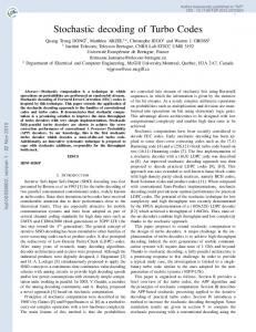
Fig. 1. A noisy data matrix after reception, where gray levels shows the distance between the correct best decision and the received soft decision. Data is the M matrix, the Checks are the areas where C1 and C2 have added their encoding. Codes C1 and C2 are eBCH(32,26). One half-iteration
Bk B
Bk+1
n1 / n2 Elementary Decodes
B BD
Fig. 2. Half-iteration decoding in turbo product code: B is the input data matrix, Bk is the decoded matrix after k half-iterations, and BD is the binary decision data matrix (only used at the last half-iteration)
an α factor (see Figure 3). The output is then rebuilt in a matrix, before being transposed and input for decoding in the next half-iteration. Iterative decoding converges to a solution after a small number of iterations (typically 4 to 6) or fails to decode. B. Related work High bandwidth architectures for turbo product codes have been investigated since very early in the production of block turbo decoder circuits [4]. A typical implementation will split k
k
the elementary decoder in three stages (reception, processing and emission), and pipeline it. Parallel decoding is possible given that all the rows may be decoded in parallel; the same with the columns. Thus a parallel decoder may be able to use a large number of elementary decoders in parallel to reach high performance ([5][6][7]). A recurrent problem is the use of intermediary buffers between half-iterations, which increases latency and the amount of logic; recent work has a trend of replacing this by a carefully designed interconnection network [6]. Another optimisation consists of storing multiple input symbols at the same address, and decoding them in parallel in a single, larger, elementary decoder [5]. Implementations may also be optimised by carefully tuning the Chase-Pyndiah algorithm parameters; a good breakdown of all parameters and their impact on a fast implementation is given in [7]. Alternative algorithms also exist, including changing the generation of test vectors such as in the Fast Chase algorithm [8]. Switching from BCH codes to RS codes also has benefits, particularly at very low error rates [9] while maintaining a relatively low complexity [10]. A similar algorithm to ours is described in [11], using the Cartesian product of the test and received vector. Our algorithm builds upon these works, by being an algebraic equivalent to the Chase-Pyndiah algorithm; hence parameter scaling will give exactly the same results in terms of decoder efficiency (however, implementation complexity influence will differ). Our algorithm is very modular, hence switching codes or test vector generations are possible. In the architecture, we keep buffers between half-iterations, and we do not duplicate elementary decoders, choosing to deep pipeline them instead. Finally, our high-level language to logic synthesis approach and tools can be compared to similar approaches using System-C [12]. II. A LGORITHM The core algorithm for turbo product code decoding is the block decoding algorithm used to decode the two linear block codes used in the product code. The turbo decoding principle is to use a SISO (Soft Input, Soft Output) linear block decoding algorithm. The first algorithm used is based on the Chase algorithm, a soft-input, hard-output algorithm, combined with a soft-output stage in [2], hence the Chase-Pyndiah algorithm. A. The Chase-Pyndiah algorithm
Rk R
Elementary Decoder
wk+1
×
+
Rk+1 R D
Fig. 3. Elementary decoder. R is the input vector (row or column), Rk is the decoded vector (row or column), Wk+1 is the extrinsic information of the decoder, Rk+1 is the decoded vector output, D is the binary decision and αk and βk are parameters of the decoder.
The Chase [13] algorithm is a linear block code decoding algorithm which uses soft decision bits (soft input) to be able to, at high signal to noise ratio, correct errors that are 2δ in squared Euclidean distance from the transmitted code word for a code C(n, k, δ), rather than (δ − 1)/2 as done by straight algebraic decoding. It is in fact a class of algorithms, with three variants. The principle of the Chase algorithm is to find the codeword the closest to the received sequence, using the soft decisions to measure this distance. With R the received sequence and Y the binary of R (the sign of ri is yi : 0 if ri < 0, 1
otherwise), Xm the codewords, the decoder has to minimise P n i=1 |ri |(yi ⊕ xmi ). To attain this, the algorithm search codewords Xm in a sphere of radius δ − 1 around Y . Those codewords are generated by perturbating Y with an error pattern T , and binary decoding the result. The generation of error patterns can be done according to three alternatives: Chase-1 where it covers all codewords in a δ − 1 sphere around Y ; Chase-2 where the error patterns are all combination of 0s and 1s in the positions of the δ/2 least reliable values of R; and Chase-3 where the number of test patterns is reduced to δ/2 + 1 from the previous one. The algorithm is then the following (as per [13]): • Search for the δ/2 least reliable positions in R (for Chase2 and Chase-3). • Compute the set of error patterns. • for each error pattern T : – Form Vt = Y ⊕ T . – Binary decode Vt in Ct . If this fails, process the next error pattern. Pn – Compute Wα (Ct ) = i=1 |ri |(yi ⊕ c0i ). – If Wα (Ct ) is the lowest metric computed, then store C 0 = Y ⊕ Ct . 0 0 • If an error pattern C was stored, decode as D = Y ⊕ C , else decode as D = Y . The Chase decoding algorithm is then a soft-input, hardoutput decoding algorithm, returning us a decision: the decoded vector D. The Chase-Pyndiah algorithm [2] is a turbo product code decoding algorithm. The elementary decoding step requires a soft-input, soft-output decoder out of the Chase algorithm. This is done by computing the reliability of all the components of the decision D of the Chase algorithm. For each bit j in the sequence, the list of candidate codewords (where the list of candidate keywords is the list of the C 0 generated above, excluding the decision D) is searched for the closest (by metric) competing codeword C such that cj 6= dj . If such a codeword exists, then the reliability is rj0 =
||R − C||2 − ||R − D||2 4
else
Rk ). Mini and Maxi are two arrays of length n, initialised at an arbitrary high value. The process is: 1) Least reliables search on Rk . 2) Test vectors processing: this part is a loop, done for each test vector. a) Generate the test vector Vt out of an error pattern, the least reliables positions and Yk . b) Binary decode the test vector. It is now a codeword Ct . If the decoding fails, process the next test vector. c) Compute the metric of the test vector. mt =
n X
|rki |(yki ⊕ cti )
i=1
d) Update each element of the Mini/Maxi arrays using the metric mt and the test vector. ( 0 then Minii = min(Minii , mt ) if cti = 1 then Maxii = min(Maxii , mt ) 3) Reliability computation fi = Minii − Maxii . If one of Maxii or Minii is arbitrary high, then no concurrent was found and the reliability is updated to fi = β(2u(fi ) − 1)2 . The extrinsic information is computed as wk+1i = fi − rki , and rk+1i = ri + αk wk+1i . If needed, the decision D is computed as di = u(fi ). By construction, the test vector with the smallest metric md recorded in the Mini-Maxi arrays is the decision word D. The concurrent word C for position i is the lowest metric test vector with ci 6= di . The concurrent word metric mc is stored in the other array (Maxii if md is in Minii , else the reverse). fi is signed, and remembering that md < mc , di = 0 means that fi = Minii − Maxii = md − mc . fi is equal to the normalisation of the log-likelihood ratio of the decision di (as explained in [14]). As such, this is an algebraic equivalent of the Chase-Pyndiah algorithm. This Mini-Maxi implementation is simple, wide and regular, allowing for parallel or vector operations: Mini-Maxi updates, reliability and output computations. Our synthesis tools shows that the binary decoder can be implemented in the same way: wide and fast.
rj0 = rj + β Where β is dependent on the iteration and the channel characteristics. B. The Mini-Maxi algorithm The Mini-Maxi algorithm use mini-maxi arrays (hence the name) to store the best metrics of all decoded test vectors. This allows the algorithm to simplify the reliability computations, and to even forego completely an explicit choice of the decided word and its concurrent words. The inputs of the Mini-Maxi algorithm are as in Figure 3, with Yk the binary vector of Rk (the signs of the symbols of
III. A RCHITECTURE In implementing this algorithm, we have chosen to maintain the overall shape of the algorithm, with well divided steps that can be done in parallel, and wide, vector type operations. The overall block turbo decoder is built out of one or more block decoders, i.e. a decoder which takes a complete data code block (a rectangular matrix of transmitted data) and operates one half-iteration on this block. The block decoder is itself built out of the elementary decoder. 2 where
u(fi ) is either 0 (for fi < 0) or 1 (fi ≥ 0).
A. The elementary decoder The elementary decoder directly applies the algorithm to an input vector (which may already have been adjusted by previous iterations) and a received vector (the vector as is out of the demodulator), and returns a modified vector (along the received vector). It is designed along the stages described in II-B (see Figure 4) where full vectors (Vt , Ct ) are propagated between stages.
Delay
R
Rk
Rk
Mini-Maxi update
mt
Delay
Mini Maxi
Rk
Reliability / Final
Rk
Ct
B. The block decoder
d)
Ct metric
Vt
c)
3)
R
Delay
Rk+1
The block decoder is based on the elementary decoder, but focusing on a full matrix of data, not just a vector. We design around the following idea: the internal memory of the block decoder is able to keep a full matrix (received and being decoded) inside. For simplicity, we suppose that the two linear block codes be the same and the data matrix be square; adaptation to two different codes C1 and C2 are shown later. Swap after each half-iteration
D R
Bi
k
Fig. 4. Elementary decoder. R is the input vector (row or column), Rk is the decoded vector (row or column), Rk+1 is the decoded vector output, D is the binary decision, αk and βk are parameters of the decoder. The 1)’s and a)’s refer to the elementary decoder stages
This decoder is implemented as a pipeline, sequenced along the three main stages. Stage 2 is itself internally a pipeline. Overall, the cycle time C of the pipeline is equal to (Tv + 4)c, where c is the stage 2 internal pipeline cycle time and Tv the number of test vectors. This architecture makes plain the ability to change code by changing the binary decoder stage b), and the fact that full vectors are passed between the stages. 1)
2) 16 cycles c
k
k
R
Delay
...
2 3 4
... ...
Reliability / Final
Least Reliables
Rk
5
Bi
k+5
R Delay
Delay
Rk+1 D R
Bi-1
BDi-1 Fig. 6. Pipelined block decoder, start decoding the first row of Bik with Bi as received matrix. Simultaneously, the block decoder writes out in column the first decoded vector of Bi−1k+5 and Bi−1 , as well as BDi−1 if this is the last half-iteration (interleaved architecture)
3)
4c
... 1
Rk
Bi-1 Reliability / Final
Delay
binary decoding
Rk
b)
k
Least Reliables
R
p
a)
test vector generation
Rk
k
2)
Least Reliables
1)
2 K times, and shifting each duplicate Tv /K cycles later than the previous one (see Figure 5). In this way, a new decoding sequence can start on stage 2 every TKv c. The maximum performance is achieved for K = Tv , where a new test vector processing sequence can start every c. The benefit of this is that we can increase the performance of the elementary decoder to a point similar to putting multiple decoders in parallel, but with only the surface duplication of stage 2 and limited to the number of test vectors.
Rk+1 D
R
Fig. 5. Pipelined elementary decoder, with K = 4 stage 2’s and Tv = 16 test vectors. Access to the duplicated stage 2’s is done according to the numbers: 1, 2 four cycles later, then 3, 4, and again 1 (which has started all 16 test vectors). Four more cycles are needed for the stage 2 to produce its results for stage 3
Acceleration of this architecture is done by duplicating stage
Our solution is to make a pipelined block decoder with a number of steps equal to the number of rows in the block. Hence a full block can be kept in the intermediary registers in the pipeline. The block decoder in Figure 6 reads its input blocks row by row. We make the block decoder write in columns into its output buffers. Once a full block has been fully decoded (last vector written), the output buffers can be used as input for the next half-iteration, reading them by rows. The full pipeline for the block decoder is built on a fully pipelined version of the elementary decoder, with a large number of steps (subdividing stages 1 and 3 of the elementary decoder, and as needed sub stages a, b, c, d in stage 2) and Tv stage 2’s. Overall, we balance the length of each stage to be able to reach the number of necessary stages in the block decoder pipeline: 32 stages for an eBCH(32, 26), 128 stages for an eBCH(128, 120). Latency is of course 32 or 128 cycles, but the sustained throughput of this decoder is one pair Rk+1 , R per cycle and is equal to its input data rate.
C. Interleaved architecture The interleaved architecture makes full use of a single block decoder, by interleaving the decoding of two blocks. While block i is being read from the input buffers and processed by the block decoder (one pair of decoded vector/received vector at a time) block i − 1 is being decoded and written to the output buffers (one pair of decoded vector/received vector at a time). Decoding Bi-1
...
Decoding Bi
R5 W 5 R6 W 6 R7 W 7 R8 W 8 R9 D9 Decoding Bi+1 R1 W 1 R2 W 2 R3 W 3 R4 W 4 R5 W 5 R6 W 6 R7 W 7 R8 W 8 R9 D9 R1 W 1 R2 W 2 R3 W 3 R4 W 4 R5 W 5 R6 W 6 R7 W 7 R8 W 8 R9 D9 R1 W 1 R2 W 2 R3 W 3 R4 W 4 R5 W 5
...
Fig. 7. Interleaved block decoding. The block decoder can do one Wk , Rj simultaneously due to the deep pipeline (Wk Write vectors to output from half-iteration k, Rj read vectors from input from iteration j, D9 write decision vectors at the end)
Once the decoding of a block is finished, the output buffers are exchanged with the input buffers, and the block decoder is ready to start the next half-iteration for this block (see Figure 6). In this scheme, by interleaving, we maintain a full pipeline while coping with the necessary rebuild of the matrix between two half-iterations (Figure 7). The two blocks are separated by 4.5 half-iterations3 , and the overall decoding of a block takes 9 half-iterations. The ninth half-iteration is needed for the pipeline equilibrium; a common approach is to use the decision after 8 half-iterations, disregarding the ninth. Overall, the complete decoder outputs a fully decoded block every 4.5 half-iterations. Each halfiteration takes 2n cycles for an (n, k, δ) elementary code. When the two linear block codes are different (with a rectangular data matrix, not square), our interleaved architecture requires a minimum of two block decoders with the adequate characteristics (number of steps in each pipeline).
R
Delay
R
Bi-1
1
Bi-1
Bi-2
1
Bi-2
Rk
...
Reliability / Final
Rk+1
Least Reliables
Bi
Rk
Reliability / Final
Bi
Least Reliables
D. Full architecture
R
R
BDi-15
Fig. 8. Full architecture: 8 block decoders in a pipeline, start reading on Bi while outputting the decision BDi−15
The fastest version of our architecture consists of throwing the maximum of hardware resources at it, that is eight block decoders in sequence (see Figure 8). We maintain the block decoder as is, with the same characteristics as before, except 3 As visible in Figure 7: a half-iteration for a block consist of two phases: Rk and Wk , and two successive blocks are aligned over alternating phases.
that, instead of swapping output buffers with input buffers at the end of decoding a block, we exchange the output buffers of block decoder i with the input buffers of block decoder i+1. This turbo decoder produces one block every half-iteration. With a code sufficiently large, and a good frequency f for each pipeline step, the data rate can be very large. IV. S YNTHESIS AND E VALUATION A. Methodology Our algorithms and architectures were developed with a high-level language, Smalltalk, implemented in parts on an FPGA target with the Madeo tool chain [15]. Algorithms and architectures are written in Smalltalk, including finite field arithmetic for the eBCH(32, 26)/eBCH(128, 120) binary decoders, and synthesised for FPGAs (logic and physical synthesis) [16]. To characterise the architectures and implementation of our algorithm, we use the following set of parameters: • n the length of the code • q the number of bits for symbol quantification (soft decision bits) • Lv the number of least reliable symbols • Tv the number of test vectors We analyse first in time and space each basic element of the algorithm, as implemented in the elementary decoder. We then give an evaluation in terms of latency, throughput and memory size of the elementary decoder and of the full architecture. B. Basic cells of the Elementary Decoder For the elementary decoder, we consider the following basic cells: • Least reliable search(stage 1): this search of the least Lv values among n uses a parallel bitonic sort. The complexity depends on Lv , but also on q since each value uses q bits. • Test vector generation(stage 2a): Combines a test pattern, the least reliable positions and the input vector Yk . Complexity is driven by Lv . • Test vector binary decoder(stage 2b): binary decode the vector, recompute parity. In the case of an eBCH(32, 26) it consists of a syndrome calculation in GF (25 ) followed by 31 comparisons and an eventual bit flip, with in parallel a parity computation. Syndrome computations have been shown to be reduction trees [16]. P • Metric(stage 2c): compute |rki |(cti ⊕ yki ). Optimised due to the fact at most Lv + 1 (parity) + 1 (binary error correction) have changed between Ct and Yk . Adders start at q − 1 bits wide, and it’s a reduction tree in shape (end at q + 1 or q + 2 bits). • Mini-Maxi update(stage 2d): The arrays Mini and Maxi are updated with the metric computation. Vector operator: n operations in parallel, with q +3 bits wide comparators. • Reliability and output computations(stage 3): vector parallel operations, n wide, with (excluding β and d) rk+1i = ri + αk (M inii − M axii − rki ). The impact of the parameters are summarised in Table I.
TABLE I S UMMARY OF THE IMPACT OF PARAMETERS n, q, Lv , Tv ON COMPLEXITY AND LATENCY
stage 1) 2 a) 2 b) 2 c) 2 d) 3)
Complexity Latency Complexity Latency Complexity Latency Complexity Latency Complexity Latency Complexity Latency
n O(qn log(n)) O(log(n)) Yes No Yes Yes Yes Yes Yes No (parallel) Yes No (parallel)
q Yes Yes No No No No Yes Yes Yes Yes Yes Yes
Lv Yes Yes Yes Yes No No Yes Yes No No No No
Tv No No Yes Yes No No No No No No No No
decoder show the interest of using a deep pipeline; an interleaved architecture shows how the deep pipeline is fully used with a single decoder. Our high-level language synthesis approach has allowed us to explore different areas in the turbo product code decoder implementation problem space. Overall, the architectures presented have a quite high memory count; we expect this to be efficient however on FPGAs, where most of the memory will be latches in logic cells, and on MP-SoCs, where local memory won’t be a limiting factor for this algorithm, but computational power. Our objectives are now complete synthesis of the interleaved architecture on FPGA, and adaptation to MP-SoCs without reconfigurable nor dedicated IPs. R EFERENCES
C. Architectural evaluation •
Elementary decoder using Tv cells for stage 2: P – Latency: allbasiccells Latency – Throughput: one vector per cycle : n symbols of q bits per cycle – Memory (bits): 2qn(Tv +6)+Lv log2 (n)+Tv (3n+q+2+2n(q+2))
•
Interleaved architecture with one block decoder – Latency: 18n f k2 – Information throughput: 9n f bit/s – Memory (bits): Mi ≈ 3(2n2 q) + Tv × n(2(q + 2) + 3) + n2
Full architecture with eight block decoders – Latency: 16n f 2 – Information throughput: kn f bit/s – Memory (bits): 8Mi − 7(n2 ) − (2n2 × q) For a frequency f of 100MHz, q = 5 bits, Tv = 16, reasonable values on our synthesis results, we can extrapolate throughput and memory amounts for the interleaved and full architectures (table II). •
TABLE II I NFORMATION THROUGHPUT AND MEMORY AMOUNTS FOR THE INTERLEAVED AND FULL ARCHITECTURES
Code eBCH(32, 26) eBCH(128, 120)
Throughput(bit/s) Interleaved Full 234M 1,88G 1,25G 11,2G
Memory(bits) Interleaved Full 40448 306176 569720 4279232
V. C ONCLUSION We have presented an implementation of the Chase-Pyndiah algorithm for decoding turbo product codes which exhibit fine grain parallelism and simplicity, adapted for execution on wide, fine grain parallel execution targets and deep pipelines. This implementation is modular in regard to the linear block code used and the method used to generate test vectors. Presented architectures for the elementary decoder and block
[1] C. Berrou, A. Glavieux, and P. Thitimajshima, “Near shannon limit errorcorrecting coding and decoding : Turbo-codes,” in IEEE ICC’93, May 1993, pp. 1064–1071. [2] R. Pyndiah, A.Glavieux, A. Picart, and S.Jacq, “Near optimum decoding of product codes,” in IEEE GLOBECOM ’94 Conference, Dec. 1994. [3] P. Elias, “Error-free coding,” IEEE Transactions on Information Theory, vol. 4, pp. 29–37, Sep. 1954. [4] P. Adde, R. Pyndiah, and O. Raoul, “Performance and complexity of block turbo decoder circuits,” in ICECS’96 Third International Conference on Electronics, Circuits and Systems, Oct. 1996, pp. 172– 175. [5] J. Cuevas, “Turbo décodage de code produit haut débit utilisant un code bch étendu,” Ph.D. dissertation, ELEC - Dépt. Electronique (Institut TELECOM/TELECOM Bretagne), UBS - Université de Bretagne Sud, 2004. [6] C. Jego, P. Adde, and C. Leroux, “Full-parallel architecture for turbo decoding of product codes,” Electronics Letters, vol. 42, no. 18, pp. 1052–1053, Aug. 31 2006. [7] C. Leroux, C. Jego, P. Adde, and M. Jezequel, “Towards gb/s turbo decoding of product code onto an fpga device,” in ISCAS 2007 : IEEE International Symposium on Circuits and Systems, May 27-30, New Orleans, USA, 2007, pp. 909 – 912. [8] S. Hirst, B. Honary, and G. Markarian, “Fast chase algorithm with an application in turbo decoding,” Communications, IEEE Transactions on, vol. 49, no. 10, pp. 1693–1699, Oct 2001. [9] E. Piriou, C. Jego, P. Adde, R. Le Bidan, and M. Jezequel, “Efficient architecture for reed solomon block turbo code,” Circuits and Systems, 2006. ISCAS 2006. Proceedings. 2006 IEEE International Symposium on, pp. 4 pp.–, 21-24 May 2006. [10] R. Zhou, R. Le Bidan, R. Pyndiah, and A. Goalic, “Low-complexity high-rate reed–solomon block turbo codes,” Communications, IEEE Transactions on, vol. 55, no. 9, pp. 1656–1660, Sept. 2007. [11] B. Geller, I. Diatta, J. P. Barbot, C. Vanstraceele, and F. Rambeau, “Block turbo codes: From architecture to application,” Information Theory, 2006 IEEE International Symposium on, pp. 1813–1816, July 2006. [12] E. Piriou, C. Jego, P. Adde, and M. Jézéquel, “System level design using system c : a case study of block turbo decoder,” in XIX Conference on Design of Circuits and Integrated Systems, Nov. 2004. [13] D. Chase, “A class of algorithms for decoding block codes with channel measurement information,” IEEE Transactions on Information Theory, vol. 18, pp. 170–182, Jan. 1972. [14] R. Pyndiah, “Near-optimum decoding of product codes: block turbo codes,” Communications, IEEE Transactions on, vol. 46, no. 8, pp. 1003–1010, Aug 1998. [15] L. Lagadec, B. Pottier, and O. Villellas-Guillen, “An lut-based high level synthesis framework for reconfigurable architectures,” in DomainSpecific Processors : Systems, Architectures, Modeling, and Simulation, S. Batttacharyya, E. Deprettere, and J. Teich, Eds. Marcel Dekker, Nov. 2003, pp. 19–39. [16] C. Dezan, C. Jego, B. Pottier, C. Gouyen, and L.Lagadec, “The case study of block turbo decoders on a framework for portable synthesis on fpgas,” in HICSS (IEEE), Mobile Computing Hardware Architectures workshop, Jan. 2006.