Jelizaveta Konstantinova, Agostino Stilli, Angela Faragasso and Kaspar Althoefer, Fingertip Proximity Sensor with Realtime Visual-based Calibration, 2016 IEEE/RSJ International Conference on Intelligent Robots and Systems (IROS 2016), 2016. (c) 2016, 2016 IEEE/RSJ International Conference on Intelligent Robots and Systems. Personal use of this material is permitted. Permission from IEEE must be obtained for all other users, including reprinting / republishing this material for advertising or promotional purposes, creating new collective works for resale or redistribution to servers or lists, or reuse of any copyrighted components of this work in other works. This is a self-archived copy of the submitted version of the above paper. There are minor differences between this and the published version.
Fingertip Proximity Sensor with Realtime Visual-based Calibration* J. Konstantinova1 , Member, IEEE, A. Stilli1 , A. Faragasso1 , and K. Althoefer2 , Member, IEEE
Abstract— Proximity and distance estimation sensors are broadly used in robotic hands to enhance the quality of grasping during grasp planning, grasp correction and in-hand manipulation. This paper presents a fiber optical proximity sensor that is integrated with a tactile sensing fingertip of a robotic hand of a mobile robot. The distance estimation of proximity sensors are typically influenced by the reflective properties of an object, such as color or surface roughness. With the approach proposed in this paper, the accuracy of the proximity sensor is enhanced using the information collected by the vision system of the robot. A camera is employed to obtain RGB values of the object to be grasped. Further on, the data obtained from the camera is used to obtain the correct calibration for the proximity sensor. Based on the experimental evidence, it is shown that our approach can be effectively used to reduce the distance estimation error.
I. INTRODUCTION A. Background The area of grasping is widely studied in the context of challenges for robotic manipulation. Current directions of research in the field of manipulation involve the development of multi-fingered robotic hands capable to sense proprioceptive information from an object [1]. Proprioceptive information along with haptic perception enables expanded understanding of the object. Consequently, object grasping and handling can be performed more efficiently by adjusting the finger posture according to the physical characteristics, position or orientation of an object. Therefore, there is a pressing need to develop sensing solutions for robotic hands. Tactile perception during grasping leads to improved quality of manipulation for the cases when the sensing device is in contact with an object. Therefore, grasp configuration can be adjusted based on haptic information and dynamic characteristics, such as contact force, slip and friction. Several multi-fingered robotic hands are equipped with tactile sensors, such as DLR-II hand [2], Gifu III hand [3] or iCub robot’s fingertips [4]. Grasp planning is often performed relying on the information obtained from the external vision system of the robot. However, such approach can lead to problems for scenarios where the fingers of the robot partially or fully occlude a *The research has received funding from the European Commission’s Seventh Framework Programme, project SQUIRREL under grant agreement No 610532 and by the Horizon 2020 Research and Innovation Programme under grant agreement 637095 in the framework of EU project FourByThree. 1 Jelizaveta Konstantinova, Agostino Stilli, Angela Faragasso are with the Department of Informatics, King’s College London, Strand, London WC2R 2LS, U.K. (e-mail: jelizaveta.konstantinova,
agostino.stilli, angela.faragasso,@kcl.ac.uk
2 K Althoefer is with the Faculty of Science and Engineering, Queen Mary University of London, Mile End Rd, London E1 4NS, U. K., (e-mail:
[email protected])
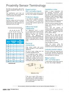
Fig. 1: System working principle: FESTO mobile robotic platform (a) makes use of a vision system (b) to detect the color of an object to be grasped with its robotic MethaHand(c). The hand is endowed with a fiber optic proximity sensor to evaluate the distance between the hand and the object, the color information collected by the camera is used to adjust in real time the calibration curve of the sensor. target object. Therefore, it might be challenging to execute a stable grasp and further to perform in-hand manipulation because of incomplete spatial information. Therefore, to solve the problem of grasp planning, tactile data is often combined with visual information. For instance, in [5] the tactile information from 6-dimensional force and torque sensor is fused with visual information from the external camera. However, in this approach the estimated shape of an object should be reconstructed. Proximity sensing can be used to improve the efficiency of the manipulation of a multi-fingered robotic hand. It can be used during initial pre-shaping of the hand; for posture readjustment, when the grasp is almost complete; or during in-hand manipulation of an object. Proximity information can help to enhance the information about the position of an object and to combine this knowledge with the data from the external vision system. In general, proximity sensors can be based on various measurement principles, namely magnetic, capacitive, inductive or optical. The use of inductive sensors is limited by metal objects only. Similarly, magnetic proximity sensors can be applied with magnetic materials only. Capacitive proximity sensors are suitable for application with various types of materials, and are broadly used for industrial applications. The capacitive sensors can be used to combine the proximity measurement with tactile sensing, such as in [6]. Proximity and tactile sensor, based on capacitive sensing principle, was developed in [7]. An electrode from conductive silicone rubber is used for proximity sensing. However, the sensor does not measure the exact distance to the object, and detects
Fig. 2: Design and prototype of the fingertip with integrated proximity and four tactile sensors. the proximity only, in addition the size of the prototype is not suitable for integration in robotic grippers. Alternatively, optical proximity sensors are used in various robotic applications. A combined optical proximity and hardness sensor employing the combination of light-emitting diodes (LED) and photodiodes was proposed in [8]. The use of LEDs improves sensor’s robustness to the external light sources; however, such design might be difficult to miniaturize and can be used to detect the proximity of an object, but not the exact distance. One of the common problems of optical proximity and distance sensors is the dependence of measurements on environmental factors, such as ambient light brightness. To solve this problem, a proximity sensor for smartphones was developed in [9]. It uses dynamic vision system and has the capability to compensate the interference from external light sources. However, due to the intended application to detect skin presence, the sensor does not take into account the reflective properties or color of an object. In the context of our work it is necessary to mention several studies where proximity sensors were successfully integrated to robotic hands. The fingertips of a Barett Hand were enhanced with optical proximity sensors in [10] to implement reactive grasping using probabilistic modeling. The object’s orientation and distance was estimated; however, the average error of such estimation is around 4 mm. In addition, the sensors that are based on an emitter and photoreceiver are quite big in size and thus their number per each fingertip is limited. In [11], manipulator TUM-Rosie was equipped with proximity sensors integrated to the fingertips. In addition, the solution benefits from an integrated camera for close distance surface texture recognition, and opticalflow detection with an external 3D camera to recognize slip. Work described in [12] presents another good example of a fingertip that detects several types of information with the help of photo-reflectors and pressure sensitive conductive rubber - tactile data, slip and proximity.
with the multifingered robotic hand called MethaHand [13], that operates in cluttered environment, like kindergarten. The target objects are the ones typically found in nurseries, such as plastic and wooden toy objects of different colors. The first prototype is described in [14]. In that work we have presented an integrated fingertip sensor, that combines force and proximity sensing elements to enhance grasping perception. The choice to use fiber optics is based on the benefits of this method. Specifically, it is a low cost solution that is robust to the electromagnetic noise, and can be easily integrated in the miniature structure. The proposed design approach using fiber optical technique allows the use of multiple proximity sensors at different locations of the fingertip due to the miniature size of fibers. In this paper we specifically focus on the development of a calibration algorithm to improve the performance of the proximity sensor based on measuring the color and reflective properties of objects by adding external vision system. Our goal is to develop a method that takes into account surface properties of an object, and decreases the error during estimation of the distance. The sensing system and the algorithm are based on the following components: • • •
Fiber optical proximity sensor integrated in the fingertip; External vision system used to obtain color of an object; Calibration algorithm that uses the color information from the camera to select an appropriate calibration.
Further on, Section II describes the design of the sensing system. In Section III we present the calibration procedure using color recognition algorithm. Then in Section IV the validation of the sensor performance is described. Section V draws out the conclusions. II. DESIGN OF THE SENSING SYSTEM The proposed design of the sensing system is composed of the fiber optical proximity sensor that is integrated in the fingertip of the robotic hand, and that uses the external vision system of the platform to improve the estimation of the distance. The structure of the system is shown in Fig. 3.
B. Motivation This paper focuses on the development and calibration of a fiber optical proximity sensor that is integrated in a robotic fingertip (Fig. 1). In our previous work we presented the development of a fingertip sensor that measures proximity and tactile information with the help of fiber optical technology (Fig. 2). The sensing system is developed for EU FP7 project SQUIRREL, and is intended to be integrated
Fig. 3: Flowchart of the proposed distance estimation algorithm using fiber optical proximity sensor and an external camera.
devices, including more expensive HD or even 4K solutions, that provide even more accurate results. III. CALIBRATION PROTOCOL
Fig. 4: Working principle of fiber optical proximity sensor. A. Fiber Optical Proximity Sensor A pair of optical fibers composes the proximity sensor (Fig. 4). In the current version of the fingertip sensor, the terminals of the fibers are located in the center of the surface of the fingertip. The measurements are performed based on the principle of light intensity modulation. The surface properties of a target object are used as a reflector. All materials, including the dark ones, are not absorbing the light completely. Therefore, the part of light beam sent by the emitting fiber is reflected and can be perceived by the receiving fiber. This is the basic principle that is used to detect the presence of objects in the proximity from the fingertip, as well as to estimate the distance from the sensor to the object’s surface. A KEYENCE fiber optical converter is used to generate the light beam and to measure the light intensity of the reflected light beam. Further on, the light intensity measurement is converted into a voltage of a range from 0 V to 4 V. Each optical fiber is 1 mm in diameter and the gap between the sending and receiving fiber of 0.4 mm is constituted of the external fiber coating. The sending light is projected to a small point-like region of the target object located at a short distance. It is assumed that the target surface of an object is orthogonal to the finger. B. Camera for Recognition of Color and Surface Properties To improve the distance to an object detection using fiber optical proximity sensor, color detection is used. It is assumed that the location of the target object is fixed or known, and is defined using an external vision system of the robot, using a segmentation algorithm. In order to select the correct calibration curve of the proposed proximity sensor we used the color information as a visual descriptor, as it is the easiest way to detect and segment an object from an image. There are different color models, such as RGB, YUV, CMY, CMYK and HSV [15]. The choice of color model is described in Section IV. A real-time image processing algorithm takes as input raw images of a commercially available USB camera that has a VGA resolution of 640*480, a frame rate of 30 fps, viewing angle of 56°and a focal length from 2 cm to 10 cm. This USB camera was selected due to its affordability and broad use in robotic applications. It is compact, since it measures only 3.6 cm in length and 0.75 cm in diameter. As the only requirement of our method is to obtain a visual information in RGB, the use of this camera can be generalized for other
To perform the calibration of the proximity sensor for the target object, our algorithm uses as an input color coefficients obtained from the external camera (Fig. 3). The RGB color code is defined prior to the grasping action and to the occlusion of an object. In addition, the RGB values are obtained recurrently after the first measurement. This is done to compensate the sudden change of lightening that might influence the reflective properties of an object.
Fig. 5: Sample objects used for calibration. A. Calibration of Light Intensity Modulation This section describes the calibration procedures carried out for fiber optical proximity sensor. As a first step it is required to record the response of the voltage caused by the light reflection from selected objects with different properties. As the reflective properties of an object depend also on the surface features of an object, we have used objects with rough, glossy and medium reflectiveness surfaces, using 28 training objects in total. In particular, three different materials were used - carton paper, shiny plastic and rough plastic. For each group of materials the objects of seven colors were selected. Some of the sample objects that were used for calibration are displayed in Fig. 5. The calibration objects were selected in a way to significantly represent all the wavelength of the visible color spectrum - from 800 nm to 390 nm. The calibration procedure was performed using a motorized linear slide. The object was fixed 50 mm opposite to the proximity sensor, and was moved towards the sensor at speed of 1 mm/s. Voltage from the KEYENCE converter was recorded along with the displacement information. In total, five trials were executed for each object. B. Color Detection to Calibrate Fiber Optical Sensor In order to perform calibration according to the obtained color code, RGB values were obtained for the training set of objects. During this test, each object was fixed in front of the camera. The colored surface of the object to be analyzed was located parallel to the lens surface of the camera at a distance of 10 cm. This distance was chosen based on the maximum focal distance of the camera used, hence 10 cm. The algorithm uses a region of interest (RoI) of 60x60 pixels, equal to 1 cm2 of the real surface. The centroid (the
center of the pixel area) was located in the center of the image with boundaries within the area of the displayed object in the image. The number of pixels was chosen to provide significant color information and to have a surface image wide enough to reject local color imperfections of the real surface, like scratches or nonuniform color distribution on the material surface. Hence, 3600 pixels were evaluated. The pixels of the RoI were then used to compute the coefficients of color model representing the color mean descriptor of the object.
TABLE I: Calibration equations used for fiber optical proximity sensor.
R
G
B
IV. CALIBRATION RESULTS
75 105 186 214
102 139 174 155
162 148 141 118
A. Calibration without an External Camera This section presents the outline of the calibration method. The previous design of the fingertip sensor estimated proximity information based on the average calibration curve that was obtained from controlled distance measurements of only 10 different objects. In this part we show the results obtained using average curve calibration method. Further on, this data is used for the comparison with the algorithm that uses color recognition. Fig. 6 displays the voltage responses obtained from the training set of objects and the calculated average curve. The second order power model can be fitted to this curve and further on is used to describe the performance of the proximity sensor: D = 0.74 ⇤ V
0.1808
17.28,
(1)
where D is the estimated distance to an object, and V is the voltage response obtained from the sensor. Based on this calibration, the maximum deviation error between the fitted line and the average response corresponds to a distance of 2 mm. The measurement range of the sensor is 20 cm. However, the average calibration method will produce larger error in case of extreme voltage responses. Our proposed method reduces this error, as multiple calibration curves are used, as it is described in the next part. B. Calibration Results with an External Vision Information The voltage readings obtained from the training set of objects are displayed in Fig. 6. From the voltage curves obtained during approaching and retraction of each object, hysteresis loops were calculated. As there are no mechanical
Fig. 6: Calibration curve obtained using average sensor response.
Voltage response V1 V2 V3 V4
Calibration equation D = 5.08 ⇤ V 0.2378 4.239 D = 2.741 ⇤ V 0.3716 D = 152.5 ⇤ V 0.02824 149 D = 28.65 ⇤ V 0.1668 22.74
TABLE II: RGB values assigned to each calibration curve. Calibration curve V1 V2 V3 V4
components involved in the design of the proximity sensor, the hysteresis loop is as small as 0.1%. It can be observed that objects of different color and reflectiveness produce relatively high variability of response. In particular, the maximum standard deviation from the calculated mean response is 2.2 V that is above 50 % from the maximum value. Therefore, in order to estimate the correct distance to a broad range of objects with different surfaces it is required to use several calibration curves. The voltage responses measured during calibration are unevenly spaced and do not cover all calibration space. Therefore, we create an evenly distributed calibration grid to cover wider of range of surfaces with less estimation error. The steps required to produce the grid are as follows: 1) The original voltage responses (Fig. 6) are sorted and interpolated to cover all calibration space (shown in gray in Fig. 7). The calibration space represents the area where the voltage response from the proximity sensors falls. 2) The adequate spacing between the target curves in the calibration grid is calculated based on the maximum distance estimation error. The value of the error should not be too small in order not to increase the complexity of the algorithm. The empirically evaluated maximum distance error is 1.8 mm that corresponds to four evenly spaced calibration curves. Fig. 7 displays the voltage responses that are used for the calibration. It can be observed, that for different objects the distance estimation range is variable. In particular, proximity sensor can be used to estimate the distance to a target object with the maximum range from 10 mm (Response V1 ) to 30 mm (Response V4 ). 3) Finally, the calibration curves are described with equations (Table I). Second order power equations of the form D = a ⇤ V b + c are best describing the voltage responses from the proximity sensors, with minimum R-squared value of 0.93. The next step of the calibration algorithm involves the association of the curves in the calibration grid with the color code coefficients obtained using an external camera. Fig. 8 demonstrates the distribution of color for the training set of objects along with corresponding voltage response curves
Fig. 7: Selected voltage responses used for calibration in the calibration space.
recorded from the proximity sensor. The detected color coefficients from the camera correspond to the original colors of the training objects. The color values are interpolated and assigned to each of the four calibration curves. Each out of four calibration curves correspond to certain color information that can be expressed in any color code. In order to select the best color representation several color models were tested. HSV or HSL are usually used as more robust color detection models in computer graphics. However, some information, such as reflective properties of an object, is suppressed during data capture. Therefore, it might be more difficult to distinguish between shiny and matte objects, such as polished and rough materials. The principle of distance estimation for fiber optical proximity sensor is based on the reflective properties of an object. Thus, the disturbance of color that is caused by the reflective surface of a shiny object is an important feature for calibration. It was found that for our case, RGB color representation provides better color estimation. The assigned RGB color values are shown in Table II. RGB values obtained from the center of the camera image and from multiple samples located within a field of view of 30°, were compared. This was done in order to evaluate the influence of the angular distance from the optical axis of the camera on the color detection algorithm, hence, potential errors during the choice of the calibration curves. This field of view was chosen based on the maximum field of view of the camera, that was 56°, and on the size of the object in the image plane, in order to avoid tip effects, like blurring, getting only data from the colored surface of the samples. Data showed that the mean difference between RGB coefficients is (55, 22, 13), this does not affect the calibration results. Finally, in order to select the calibration for a novel object, the measured RGB value is associated with the most suitable calibration curve and assigned RGB. Measured RGB values are compared with the assigned ones using three-dimensional Euclidean distance. The RGB values from an object are obtained in real-time, and in case environmental conditions, such as light change, the used calibration curve is updated with the other curve from the grid.
Fig. 8: Obtained color code mapped to voltage responses from the proximity sensor. Black lines show calibration curves, and colored lines correspond to voltage responses from the proximity sensor, the color of the line reflects RGB color value from the camera. TABLE III: Comparison between color calibration and average calibration for novel objects. Object
Black plastic Light brown wood White paper Purple fabrics Green cellophane Gray polyurethane Red rubber tape
Calibration curve V1
Color calibration Mean Max error, error, mm mm 3 5
Average calibration Mean Max error, error, mm mm 10 30
V3
2
5
2
11
V4 V2 V3 V1 V4
1 1 1 1 2
3 6 5 3 5
5 6 1 15 3
9 25 7 33 8
V. EVALUATION EXPERIMENTS To evaluate the performance of the proximity sensor and the calibration algorithm, experiments were conducted using the objects that were not used during the calibration. Seven objects were used - light colored wooden block, black plastic box, white paper, purple fabrics toy, gray expanded polyurethane, green cellophane, and red rubber tape. The objects were positioned on the linear slide and moved towards the proximity sensor, at the same time the camera was recording color values in real-time. The results of the distance estimation using the proposed calibration algorithm are shown in Fig. 9. The calibration curves have different sensing range, as it was mentioned in the section above. Therefore, the length of distance estimation for each object varies. Distance estimation is displayed relatively to the reference curve (x = y), which is represents perfect estimation. The distance estimation errors for the test objects are shown in Table III. To evaluate the improvement of the sensor performance the distance estimation is compared with the previous version that is based on the average calibration curve with no use of the external camera, as it is described in Section IV. The responses are displayed in Fig. 10 and in Table III. The results show that in this case there is comparatively large distance estimation error. In addition, this algorithm does
not take into account the range of distance estimation for the calibration that produces large noise for larger distances. For the proposed algorithm this feature is taken into account, and distance estimation is performed only for the calibrated range - 10, 15, 25 and 35 cm for responses V1 to V4 respectively. Therefore, it was shown that the proposed color calibration algorithm reduces the distance estimation error for the fiber optical proximity sensor in the majority of cases. For some objects, the distance estimation error does not improve much, as the chosen calibration (V2) is close to the average calibration.
calibration curve demonstrates the significant improvement of the distance estimation error for different materials. In particular, the mean error was reduced to 2 mm. In future development of the proximity sensor it is planned to perform extended testing of the system for real-time grasping tasks. Current algorithm assumes that camera looks at the object using the same angle as at least one finger. It is possible to estimate the orientation of the fingertip using forward kinematics of the robotic platform, and then to apply the corresponding calibration for the fingertip. Although the proposed solution of proximity sensing is developed for grasping applications, it can also be used for any other robotic system where proximity and distance detection from unknown objects is required. R EFERENCES
Fig. 9: The results of distance estimation using calibration algorithm relatively the linear reference line (x = y).
Fig. 10: The results of distance estimation without the use of calibration algorithm and without an external camera relatively the linear reference line (x = y). VI. CONCLUSIONS This paper presents a fingertip proximity sensor that uses real time visual-based calibration algorithm. Our target was to develop a distance sensing system that is capable to take into account the surface properties of a target object, such as color, and to adjust the calibration accordingly in real time. In case the environmental light and, respectively, the reflective properties of an object are changing, the algorithm updates the calibration accordingly. The proposed algorithm is developed to work with uniformly colored objects. It uses the mean color information from RoI that can partially reduce the distance estimation error. However, more tests are required. The proposed solution of a fiber optical proximity sensor calibration can be easily integrated for the broad range of different robotic platforms that use an external camera. In our experiments we have used a low resolution vision system, with a short focal length. The use of more advanced cameras, with bigger pixel matrix can improve the color estimation, hence, the quality of our algorithm. The comparison with the first prototype’s calibration method that uses only one
[1] J. Tegin and J. Wikander, “Tactile sensing in intelligent robotic manipulation a review,” Industrial Robot: An International Journal, vol. 32, pp. 64–70, 2005. [2] J. Butterfab, M. Grebenstein, H. Liu, G. Hirzinger, and J. B. De, “DLR-Hand II : Next Generation of a Dextrous Robot Hand,” in 2001 IEEE International Conference on Robotics & Automation, pp. 109– 114, 2001. [3] T. Mouri, H. Kawasaki, K. Yoshikawa, J. Takai, and S. Ito, “Anthropomorphic Robot Hand : Gifu Hand III,” in ICCAS2002, pp. 1288–1293, 2002. [4] A. Schmitz, M. Maggiali, L. Natale, B. Bonino, and G. Metta, “A Tactile Sensor for the Fingertips of the Humanoid Robot iCub,” in 2010 IEEE/RSJ International Conference on Intelligent Robots and Systems, pp. 2212–2217, 2010. [5] J. Bimbo, S. Rodriguez-Jimenez, H. Liu, X. Song, N. Burrus, L. D. Senerivatne, M. Abderrahim, and K. Althoefer, “Object pose estimation and tracking by fusing visual and tactile information,” in IEEE International Conference on Multisensor Fusion and Integration for Intelligent Systems, pp. 65–70, 2012. [6] H.-K. L. H.-K. Lee, S.-I. C. S.-I. Chang, and E. Y. E. Yoon, “A Capacitive Proximity Sensor in Dual Implementation with Tactile Imaging Capability on a Single Flexible Platform For Robot Assistant Applications,” in 19th IEEE International Conference on Micro Electro Mechanical Systems, no. January, pp. 606–609, 2006. [7] D. Goeger, M. Blankertz, and H. Woern, “A tactile proximity sensor,” in Proceedings of IEEE Sensors, pp. 589–594, 2010. [8] T.-Y. L. T.-Y. Lin, P.-P. Chao, W.-P. C. W.-P. Chen, and C.-H. T. C.H. Tsai, “A novel 3D optical proximity sensor panel and its readout circuit,” in IEEE Sensors, (Kona), pp. 108–113, 2010. [9] J.-y. Won, H. Ryu, T. Delbruck, J. H. Lee, and J. Hu, “Proximity Sensing Based on Dynamic Vision Sensor for Mobile Devices,” Ieee Transactions on Industrial Electronics, vol. 62, no. 1, pp. 536–544, 2014. [10] K. Hsiao, P. Nangeroni, M. Huber, A. Saxena, and A. Y. Ng, “Reactive grasping using optical proximity sensors,” in 2009 IEEE International Conference on Robotics and Automation, pp. 2098–2105, Ieee, May 2009. [11] A. Maldonado, H. Alvarez, and M. Beetz, “Improving robot manipulation through fingertip perception,” in 2012 IEEE/RSJ International Conference on Intelligent Robots and Systems, pp. 2947–2954, Ieee, Oct. 2012. [12] H. Hasegawa, Y. Mizoguchi, K. Tadakuma, M. Ishikawa, and M. Shimojo, “Development of intelligent robot hand using proximity, contact and slip sensing,” in 2010 IEEE International Conference on Robotics and Automation, pp. 777–784, Ieee, May 2010. [13] J. S. Dai, D. Wang, and L. Cui, “Orientation and workspace analysis of the multifingered metamorphic hand-metahand,” IEEE Transactions on Robotics, vol. 25, no. 4, pp. 942–947, 2009. [14] J. Konstantinova, A. Stilli, and K. Althoefer, “Force and Proximity F ingertip S ensor to Enhance Grasping Perception,” in IEEE/RSJ International Conference on Intelligent Robots and Systems, p. 1, 2015. [15] R. C. Gonzalez, R. E. Woods, and S. L. Eddins, Digital Image Processing Using Matlab - Gonzalez Woods & Eddins.pdf, vol. 624. Prentice Hall Upper Saddle River, NJ, 2004.