Proceedings of the 20th Annual International Conference of the ZEEE Engineering in Medicine and Biology Society, Vol. 20, No 6,1998
FINITE ELEMENT MODELING OF THE NEURONELECTRODE INTERFACE: SEALING RESISTANCE AND STIMULUS TRANSFER AT TRANSITIONS FROM COMPLETE TO DEFECT SEALING J.R. Buitenwe;, W.L.C.Rutten* and E. Marani** *Institutefor Biomedical Technology, Faculty of Electrical Engineering, University of Twente, P.O. Box 217,7500 AE Enschede, The Netherlands ** Dept. of Physiology, Faculty of Medicine, University of Leiden, P.O.Box 9604, 2300 RC Leiden, The Netherlands *Email:
[email protected]
-
The quality of the electrical contact between a cultured neuron and a substrate embedded microelectrode is of importance for effective transfer of an extracellular applied stimulus current to the intracellular potential. It is affected by the resistance of the seal, i.e. the gap between the cell membrane and the substrate, which restricts the leakage current, thereby favouring the efficiency of the stimulation current. The effects of variations in the geometry of the neuronelectrode interface on the sealing resistance and on the stimulus transfer are studied using a finite element model of this interface. Variations in the geometry of the neuron-electrode interface are represented by the excentricity, x,, of a pillbox shaped neuron with radius re, cultured on an electrode with radius re. The results indicate a sharp decrease in both sealing resistance and stimulus transfer when a transition occurs from complete sealing to defect sealing. At that point the leakage current splits up into a current through the gap and a current through the sealing defect.
Abstract
Keywords - Cultured neurons, multi-electrode arrays, Neuron-electrode interface, sealing resistance, stimulus transfer, finite element modeling
I. INTRODUCTION Planar substrate electrode arrays (PEAS) offer the possibility to contact neuronal cultures with a large number of cell-size electrodes [1][2]. In our project, PEAS are used as a tool for the development of a cultured neuron probe, a new type of neuro-electronic interface for highly selective stimulation
purposes. For effective transfer of an extracellular applied stimulus current to the intracellular potential, the quality of the electrical contact between a cultured neuron and an electrode is of importance [3]. This quality is affected by the resistance of the seal, i.e. the gap between the cell membrane and the substrate, which restricts the leakage current, thereby favouring the efficiency of the stimulation current (fig. la). In previous work, a method for measurement of the sealing resistance in the neuron-electrode interface was proposed as a first step towards assessment of the quality of this contact [4]. This method was based on a model of a neuron-electrode interface geometry in which the electrode was completely covered, i.e. sealed by the neuron. Now, this model is extended to include the effects of varying neuron-electrode geometries on the transfer of extracellular applied stimuli. Variations in the geometry of the neuronelectrode interface are represented as an excentricity, xc, of a neuron with radius r,, cultured on an electrode with radius re (fig. lb). When x, increases from zero, the sealing resistance will decrease due to the altering geometry of the gap between the cell membrane and the substrate. At xc=rc-re,a transition occurs from complete sealing to defect sealing: The leakage current splits up into a current through the gap and a current through the sealing defect. Further increase of x, will also decrease the area of the patch membrane (fig. IC). The effects of the neuron excentricity on the sealing resistance and on the stimulus transfer are computed using finite element analysis. The transitions are studied at several geometries by varying the radii of neuron and electrode. The results indicate a sharp transition in both sealing resistance and stimulus
fig. I (a) Schematic presentation of the neuron-electrode interface. The eficiency of the stimulation current is increased by restriction oj
the leakage current through the gap. (b) Model assumption on the geometry of the neuron-electrode interface: the neuron is positioned excentrically on the electrode (with excentricity x,). (c)Electrical equivalent circuit of the (passive) neuron-electrode inte@ace. The sealing resistance and area of the patch membrane are modulated by the excentricity, x , of the neuron. 0-7803-5164-9/98/$10.000 1998 IEEE 2854
transfer around &=rc-re In case of complete sealing the stimulus transfer remains relatively constant.
11. METHODS In fig. 2a, the simplified geometry of the neuron-electrode interface is depicted. The neuron is modeled as a pillbox shaped cell of radius r,=7 pm, positioned with an excentricity x,, on top of an electrode of radius re=5 pm. The electrode surface is represented by the bottom of a 800 nm deep hole. Between the lower membrane surface of the cell and the substrate, the sealing gap is modeled (but not over the electrode area). The geometry of the neuron-electrode interface is implemented in ANSYS Finite Element Software release 5.3 (SAS IP inc., Houston). The medium, surrounding the neuron-electrode interface is modeled as a pillbox shaped volume conductor of conductivity 0,,,=1.65 S/m, radius
.....
Elcctrode area
-
r, = re + r, ++xc, positioned at %xc. The neuron is modeled as a pillbox shaped cavity inside this volume conductor (fig. 2b). The sealing gap could not be meshed when implemented with its actual thickness of 10 nm [ 5 ] . Therefore the conductivity of the gap (the dark ring in fig. 2b) was corrected for the difference between modeled and actual thickness. All volumes in the model are meshed and filled with tetrahedral shaped volume elements of type SOLID98 . The intracellular potential is assumed constant over the entire intracellular space. Therefore, the intracellular potential can be represented by a single node. The electrical properties of the (passive) neurdnal membrane are implemented by capacitive circuit elements connecting the neuronal membrane to this intracellular node (fig. 2c). All capacities are scaled to a value of lpF/cm using the area represented by the membrane nodes. The electrode surface is modeled as an equipotential area by coupling all nodal potentials to one principal node in the area. A current applied to this principal node will result in an equivalent uniform current density over the entire electrode surface. The electrode-electrolyte interface impedance is added to the model by connection of circuit elements between the principal node of the electrode area and a contact node, representing U,,, (see fig. IC and fig. 2c). Finally, the shunt capacity (between the electrode lead and the medium, across the insulation layer) is modeled by a capacitive circuit element. The nodes of the upper surface of the volume conductor (medium) and of the circular outer surface are set to zero potential. A unity current is applied to the contact node. The finite element problem is solved at frequencies f= 300 Hz, 500 Hz, 700 Hz, 1 kHz, 3 kHz, 5 kHz, 7 kHz, 10 kHz and 20 kHz,for cell excentricities x,=O up to x,=4.0 pm, in steps of 0.2 pm. The excentricities x,=1.8 pm and x,=2.0 pm are left out since a proper meshing could not be produced for these geometries. From every solution the computed potentials at the contact node and the intracellular node are saved. Since unity current is applied to the contact node, the potential of the contact node, U,,,,equals the total impedance of the neuron-electrode equals system and the potential of the intracellular node, Uinwa, the stimulus current transfer function.
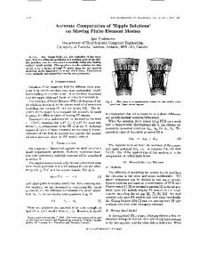
111. RESULTS In fig.3 the transition from complete (x,rc-re) is illustrated by the locations of the equipotential surfaces in the volume conductor (sealing gap and medium). For convenience, the circuit elements modeling the membrane, the electrode impedance and the shunt capacity are left out. When the cell is positioned right on top of the electrode, %=O, all equipotential surfaces are located in the sealing gap, which indicates that the potential drops mainly over the sealing gap (fig.3a). At x,=1.6 pm, the sealing is still complete and the potential drop is still located in the sealing gap (fig. 3b). When the sealing becomes defect, at x,=2.2 pm, the potential drop is extended to the rest of the volume conductor, indicating a much larger leakage current (fig. 3c).
(c> fig. 2
( a ) Simplified geometry of the neuron-electrode inte$ace. The neuron is modeled as a pillbox shaped cell and is positioned on top of an electrode with a small sealing gap between the cell membrane and the substrate. ( b ) Finite element model of the neuron-electrode inte$ace .The neuron is modeled as a cavity inside a volume conductor respresenting the surrounding medium. The conductivity of the sealing gap is corrected for its actual thickness. ( c ) The intracellular space is assumed to be equipotential and therefore modeled with a single node. The membrane is represented by capacitive circuit elements, connecting the intracellular node to the nodes on the cell upper and lower su$ace. Finally, the electrode impedance and shunt capacity are added to the model using circuit elements. 2855
The impedance loci (the imaginary part vs. the real part for each computed frequency) of the total neuron-electrode system are depicted in fig. 4a. The loci are grouped in two clusters, which indicate a sharp transition from complete to defect sealing. In fig. 4b, some results from previous measurements on cultured electrode arrays are redrawn from [4]in order to allow comparison with fig. 4a. The measured loci are grouped in clusters, similar to the clusters in the computed results. This does not surprise, since only a few electrodes in the culture were completely covered by a cell. The clustering is also present in the computed transfer of the applied stimulus current to the intracellular potential, H,(f), as can be concluded from the Bode diagram in fig. 4c. For stimuli in the frequency range from 100 Hz to 3 kHz the transfer function decreases with a factor ten when the sealing becomes defect. In fig. 5a the sealing resistance is depicted as a function of cell excentricity, x,. When the sealing is complete (&