Available online at www.sciencedirect.com
Procedia CIRP 8 (2013) 510 – 515
14th CIRP Conference on Modelling of Machining Operations (CIRP CMMO)
Finite Element Modelling of Conventional and Hybrid Oblique Turning Processes of Titanium Alloy Riaz Muhammad*, Anish Roy, Vadim V. Silberschmidt Wolfson School of Mechanical and Manufacturing Engineering, Loughborough University, Loughborough, Leicestershire LE11 3TU, UK U * Corresponding author. Tel.: +44/(0)1509/227566;.E-mail address:
[email protected].
Abstract This study is a part of the on-going research at Loughborough University, UK, on finite element (FE) simulations of ultrasonically assisted turning (UAT) coupled with hot machining processes. In UAT, vibration is superimposed on the cutting tool movement, resulting in several advantages of the process, especially in machining of high-strength engineering materials. Direct experimental studies of machining processes are expensive and time consuming, especially when a wide range of machining parameters affects, f complex thermo-mechanical high-deformation processes in machined materials. In recent years, a use of mathematical simulations and, in particular, FE techniques has gained prominence in the research community. These techniques provide an accurate and efficient modelling paradigm for machining processes. In the present work, thermo-mechanically coupled three-dimensional FE models of conventional, ultrasonically assisted turning and a new hybrid turning technique called hot ultrasonically assisted oblique turning for a case of titanium alloy are presented. A nonlinear temperature-sensitive material behaviour is incorporated in our numerical simulations based on the results of the split-Hopkinson pressure bar tests. The simulation results obtained at different f cutting conditions are compared to elucidate main deformation mechanisms responsible for the observed changes in the material responses to various cutting techniques. © 2013 2013The TheAuthors. Authors.Published Published Elsevier Open access under CC BY-NC-ND license. © by by Elsevier B.V.B.V. Selectionand and/or peer-review under responsibility of The International Scientificof Committee of Conference the 14th CIRP Conference on Selection peer-review under responsibility of The International Scientific Committee the “14th CIRP on Modeling of Machining Modelling of in the person the Settineri Conference Chair Prof. Luca Settineri Operations” in Machining the person ofOperations" the Conference Chair Prof.of Luca Keywords: Finite element; Conventional turning; Hybrid turning; Titanium alloys;
1. Introduction The application of Ti alloys is increasing continuously in components require high-strength, light weight and high corrosion resistance. The limiting factor for application of titanium in engineering structures is the problem faced in its machining. This is primarily due to some inherent properties of Ti alloys such as low thermal conductivity, which impedes heat transfer out of the process zone, generating high temperatures during the cutting process. Also, these alloys are chemically reactive with almost all cutting tool materials, thus reducing the tool life. Hence, conventional machining of Ti alloys often proven to be uneconomical [1]. In the current work, a new hybrid machining technique called hot ultrasonically assisted turning -Ti alloy. In
this technique, hot machining was combined with ultrasonically assisted turning (UAT) to achieved combine advantages of both techniques in turning of intractable alloys. In the recent past, numerous techniques have gained precedence in modelling the response of a material when subjected to machining processes. Typically, finiteelement (FE) techniques have been used extensively in modelling of orthogonal turning processes, to understand the effect of machining parameters on the level of cutting forces [2, 3]. However, an industrially-relevant machining process needs to consider the motion of the tool in axial/feed direction and account for all the three components of cutting forces. This process is typically referred to as oblique turning. An over-simplification of the cutting process using an orthogonal formulation leads to inaccuracies in predictive capabilities of the developed models.
2212-8271 © 2013 The Authors. Published by Elsevier B.V. Open access under CC BY-NC-ND license. Selection and peer-review under responsibility of The International Scientific Committee of the “14th CIRP Conference on Modeling of Machining Operations” in the person of the Conference Chair Prof. Luca Settineri doi:10.1016/j.procir.2013.06.142
511
Riaz Muhammad et al. / Procedia CIRP 8 (2013) 510 – 515
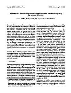
Therefore, in the current study, a 3D thermomechanically coupled finite-element model for conventional turning (CT), hot conventional turning (HCT), UAT and HUAT of the studied Ti alloy was developed. The model was used to investigate the benefit of a new technique HUAT when compared to CT, HCT and UAT. 2. Experimental Work The current experimental setup consisted of a modified Harrison 300 lathe machine, with a custombuilt ultrasonic transducer mounted on a wave-guide, a force-measurement and data-acquisition systems, a charge amplifier, an A/D converter, a thermocouple, an infra-red camera and a band-resistance heater. A Kistler piezoelectric dynamometer (KIAG SWISS Type 9257A) was used to measure the radial and tangential component of cutting-forces. The ultrasonic transducer was mounted on the dynamometer (Fig. 1) with adequate insulation to protect it from electrical disturbances, generated during machining operations. Additionally, a micrometric dial gauge was used to ensure an accurate depth of cut.
insert (DNMG-150608 supplied by Seco) was employed as a cutting tool. All experiments were carried out in dry cutting condition without any lubricant. Several tests for CT, HCT, UAT and HUAT were carried out, and the cutting forces were measured. Each experiment was repeated at least five times to get statistically consistent data. The cutting forces reduced significantly during UAT when compared to those obtained in CT. In addition to that, the cutting forces further reduced with an application of external heat to the workpiece material in HUAT compared to CT and UAT, respectively. In general, a part of the force reduction in UAT and HUAT offered considerable benefits, in particular, the elimination of the chatter noise during operations and better surface finish [4, 5]. The temperature of the process zone was investigated with an infra-red system (FLIR SC3000 thermal system). The infra-red system was used in CT, HCT, UAT and HUAT tests and temperature of the process zone was measured. A relatively high temperature in HUAT was observed when compared to CT, HCT and UAT. Table 1. Cutting parameters used in experiments and FE simulations Parameters
Value
Cutting speed, V (m/min)
10
Depth of cut, ap (mm)
0.1-0.5
Feed rate, fr mm/rev
0.1
Frequency, f (kHz)
20
Amplitude, a (μm)
8
Cutting edge radius, r (μm)
25
Temperature, °C
20,100, 200, 300
3. Finite Element Model Fig. 1. Schematic of experimental setup For bulk heating of the workpiece material, the bandresistance heater, encapsulating the workpiece, was used to heat up the workpiece to a required temperature. The 1.1 kW heater was capable of heating the workpiece up to 600°C. However, in the current study, the workpiece was heated to a temperature of 300°C ± 10°C. The Teflon-coated, calibrated K-type thermocouple and the FLIR SC3000 thermal system are used to measure the temperature of the workpiece in hot machining. The cutting conditions used in the experiments are listed in Table 1. An ingot -Ti-based alloy (Ti15V3Cr3Al3Sn) having an initial diameter of 65 mm and length of 500 mm was used as a workpiece material, and a commercial PVD coated with TiAlN
A part of deformable workpiece having a length of 5 mm, width of 1.3 mm and height of 0.5 mm + ap was modelled in the oblique turning of Ti15V3Cr3Al3Sn (Fig. 2). Initially, eight-node hexahedral elements with a minimum length of 0.05 mm were used to mesh the workpiece. Later on, in the start of the simulation, eightnode hexahedral elements were converted into 5-node tetrahedron elements with element size of 0.0275 mm due to the lack of support of global re-meshing. The global re-meshing technique was used to separate chip from the workpiece material based on the numbers of simulation increments. The cutting tool was modelled as a rigid body with heat-transfer capabilities. The rake angle of the cutting insert was 14.5° with a nose radius of 0.8 mm, the end
512
Riaz Muhammad et al. / Procedia CIRP 8 (2013) 510 – 515
relief angle of 0°; the cutting edge radius was 25 μm. The cutting tool was initially modelled in Pro-Engineer and was imported to Patran-3D to discretise it to fournoded tetrahedral element. The workpiece was translated in the tangential direction with a set cutting velocity. The cutting tool was also translated in the feed direction with a constant feed rate of 0.1 mm/rev. In UAT and HUAT, ultrasonic vibration was superimposed on the cutting tool movements in the tangential direction. Additionally, for both HCT and HUAT, initial temperature was applied to the workpiece to incorporate hot machining in the model.
4. Results and Discussions 4.1. Cutting Forces The developed oblique model gives all the three components of cutting forces. The tangential cutting force (Fx) of magnitude 110 N was observed as shown in Fig. 3. A radial component (Fy) of 48 N and an axial component (Fz) of 20 N was observed at a cutting velocity of 10 m/min, feed rate of 0.1 mm/rev and depth of cut of 300 μm. At the start of the FE simulation, the level of cutting forces on the cutting tool was zero. The magnitudes of cutting forces were increased rapidly after an initial tool contact with the workpiece and reached to a steady state level in CT. The observed steady state levels of forces were used in the current study for the purpose of comparison.
Fig. 2. Schematic of cutting tool and workpiece in oblique model In FE simulations, a piece-wise linear material model was used to represent the response of the studied alloy at various strain rates and temperatures. The stress-strain relationship was obtained from a series of splitHopkinson tests performed [3, 6]. The data comprised a combination of four different strain rates (0.1 s-1, 1 s-1, 3300 s-1, 105 s-1) and four different temperature values (20°C, 200°C, 600°C, 950°C). Details of the material data are available elsewhere. The material properties of Ti15V3Cr3Al3Sn are = 87 GPa, = 0.3, = 4900 kg/m3, where , and are density, respectively. The thermal conductivity of the Ti15V3Cr3Al3Sn is = 8.08 W/mK. A behaviour of the material with temperature-dependent thermal expansion and specific heat (C Cp) was incorporated into the model; additional details are available elsewhere [6]. The modified shear-friction model was used to simulate friction between the materials of tool, chip and workpiece [7].
where is a friction stress, is the equivalent stress, is the relative sliding velocity, is the critical sliding velocity below which sticking is simulated, is the friction coefficient and is the signum function.
Fig. 3. Three components of cutting forces in CT and UAT at (V =10 m/min; ap = 0.3 mm; fr = 0.1 mm/rev). Application of ultrasonic vibration to the cutting tool produced a significant reduction in the level of cutting forces [8]. In the process of vibration of the cutting tool, it separated from the workpiece in each cycle of tool movement, resulting in a considerably reduced cutting force. During the penetration stage of the tool in UAT, the tool reached the peak of cutting forces for tangential, radial and axial directions. However, during the relaxation stage, the cutting forces in all three directions started to decline and ultimately vanished to the tool disengagement (see Fig. 3).
Riaz Muhammad et al. / Procedia CIRP 8 (2013) 510 – 515
The cutting force component Fx declined from 110 N to 35 N (68 %). Also, a considerable reduction of 66% (from 48 N to 16 N) was observed for Fy in UAT. In addition to this, ultrasonically assisted turning yields a significant reduction of 55% (20 N to 9 N) in Fz. The simulations of CT and UAT were carried out for various depths of cuts, and a considerable reduction in forces was observed in UAT w when compared to CT (see Fig. 4). The cutting forces depended strongly on the tool edge radius, particularly the radial component of the force in both CT and UAT. With an increase in the tool cutting edge radius, the contact region between the tool and workpiece k increased, leading to more shearing of the material at the process zone. For a cutting tool having tool edge radius of 25 μm and zero rake angle, the tangential, radial and axial cutting forces in CT were 120 N, 63 N and 25 N, respectively, whereas in UAT, an average of 41 N, 24 N and 12.9 N of Fx, Fy and Fz, respectively, were observed. In UAT, average reductions of 45-70% in all three components of cutting forces were noted compared to those observed in CT (see Fig. 5).
reduced from 25 μm to 0 μm in CT. The same effect generated a more pronounced force reduction in UAT. A 15%, 69% and 68% reduction in Fx, Fy and Fz, respectively, were observed in that case. A considerable rise of 20%, 44% and 84% in Fx, Fy and Fz, z respectively, y was observed in CT with an increase in the radius from 25 μm to 75 μm; on the other hand, in UAT it was 27%, 71% and 78%. A further rise in tool edge radius from 75 μm to 100 μm yielded a rise of 7%, 17% and 23% in Fx, Fy and Fz, respectively, in CT and 10%, 21% and 26% in UAT. Hence, the tool edge radius has a strong effect on the cutting forces, particularly on the radial component. The results demonstrated the importance of tool conditions in turning of Ti15V3Cr3Al3Sn in CT and hybrid turning processes.
Fig. 5. Effect of tool edge radius on cutting forces (V =10 m/min; ap = 0.3 mm; fr = 0.1 mm/rev).
Fig. 4. Comparison of cutting forces at various depth of cuts in CT and UAT The forces Fx, Fy and Fz are reduced by 15%, 58% and 44%, respectively, when the tool edge radius was
A newly developed FE model for HUAT was used to investigate the cutting forces at various externally applied temperatures. A significant reduction in Fx, Fy and Fz in HCT and HUAT at 300 μm depth of cut and at 300°C was observed as shown in Fig. 6. The reduction in Fx, Fy and Fz in HCT was 20% 22% and 44%, respectively, when compared to CT at room temperature. Whereas, the reduction in HUAT was 41%, 34% and 36% when compared to results obtained at room temperature in UAT. The results obtained in HCT and HUAT show that the reduction in cutting forces was more dominant in HUAT than in HCT. The obtained FE simulation and experimental results were in good agreements (see Fig. 6). A gradual reduction in all three components of cutting forces was observed with an application of
513
514
Riaz Muhammad et al. / Procedia CIRP 8 (2013) 510 – 515
external heat to the workpiece material in HCT and HUAT as shown in Fig. 7. However, the reduction in radial and axial component of cutting forces vanished at 500°C in HUAT. The possible reason was the excessive thermal softening of material in the process zone. Hence, a temperature of 300°C was recommended for HUAT in the machining of Ti15V3Cr3Al3Sn. The reduction in cutting forces in HCT and HUAT can be attributed to the thermal softening of Ti15V3Cr3Al3Sn, as the flow stress of the studied alloy is a function of temperature.
the cutting tool in the form of vibration. The application of vibration to the cutting tool increased its relative velocity causing high plastic deformation of the workpiece material, which resulted in high temperature by (105°C) when compared to CT. The application of external heat to the workpiece material in HCT and the novel hybrid machining process, HUAT, resulted in the temperature increase in the process zone, depending on the amount of heat supplied to the workpiece material. In HCT and HUAT, the temperature of the process zone was higher when compared to CT and UAT, respectively. The amount of initial heat imposed on the workpiece material also increased the amount of heat transfer to the cutting tool. In HUAT, the process zones temperature was higher than that in HCT due to the effect of vibration on the cutting tool as shown in (Fig. 9). However, in HUAT, the process zone temperature was somewhat higher by (55°C) when compared to HCT. The main reason for a lower temperature rise in HUAT (when compared to HCT) was the reduction in plastic heat generation.
Fig. 6. Cutting forces in CT, UAT, HCT and HUAT (V =10 m/min; ap = 0.3 mm; fr = 0.1 mm/rev; T = 300°C).
Fig. 8. Heat generation in CT and UAT (V =10 m/min; ap = 0.3 mm; fr = 0.1 mm/rev)
Fig. 7. Cutting forces at various temperatures in HCT and HUAT 4.2. Thermal Analysis In CT, HCT, UAT and HUAT, the temperature of the process zone was investigated with the developed 3D thermo-mechanically coupled FE model, as shown in Fig. 8. In UAT, a relatively higher temperature was observed along the contact area of the tool-workpieceinterface. Temperature in UAT was higher when compared to CT at the maximum penetration of the tool; the possible reason for the high temperature of the process zone in UAT was application of extra energy to
The maximum temperature was observed at the centre point of the tool edge in contact with the workpiece material, with some drops towards the ends of the cutting length in CT and hybrid turning processes (Fig. 10). These results can be attributed to the convective heat transfer from the rake surface of the tool to the environment. A temperature distribution on the rake face of the tool changed with the tool position in UAT and HUAT. At the penetration stage of UAT and HUAT, higher temperatures of approx. 105°C and 303°C, respectively, were observed on the rake face due to severe plastic deformation and the frictional effect. Whereas in the relaxation stage, the tool separated from the workpiece; thus, there were marginally lower temperature levels were observed with maxima of approx. 101°C and 295°C, respectively, on the rake face. On average,
Riaz Muhammad et al. / Procedia CIRP 8 (2013) 510 – 515
temperature magnitudes of 299°C and 103°C were observed in one complete vibratory cycle in HUAT and UAT, respectively.
Fig. 9. Heat generation in HCT and HUAT (V =10 m/min; ap = 0.3 mm; fr = 0.1 mm/rev). In CT and HCT, with the tool being in continuous contact with the workpiece, steady distributions of temperature on the rake face was observed. The maximum levels of temperature observed in CT and HCT were 100°C and 290°C, respectively. Hence, the temperatures on the rake face in UAT and HUAT were slightly higher by (3 13°C) compared to those observed in CT and HCT, respectively. In HCT and HUAT, the externally applied heat to the workpiece material and high process zone temperature increased the amount of heat transfer to the cutting tool resulted, high level of temperatures on the rake face of the tool. A linear increased in the rake face temperature was observed with an increase in externally applied heat to the workpiece material.
Fig. 10. Temperature distribution on the rake face of tool 5. Conclusions A new hybrid machining process HUAT was introduced in the current work. The experiments and FE model were used to investigate this process in
comparison with three other techniques. For FE modelling, a 3D thermomechanically coupled finite element model was developed for oblique turning processes. The model was used to investigate the effect of vibration superimposed on the cutting process in UAT on the cutting forces and temperature of the process zone. The developed model was extended to HUAT and HCT. A parametric study was carried out for HUAT and significant reduction in all three components of forces was observed when compared to CT. This new hybrid technique can be used for machining of hard-to-cut alloys with lower average cutting forces. In addition to that, the FE model was used to investigate the effect of tool conditions on cutting forces in CT and UAT. A significant increase in cutting forces was observed with an increase in the tool edge radius. The FE model was validated by the experimental results and the advantages of the developed novel hybrid turning process were highlighted. References [1]. Arrazola, P.J., A. Garay, L.M. Iriarte, M. Armendia, S. Marya, and F. Le Maitre, 2009, Machinability of titanium alloys (Ti6Al4V and Ti555.3).Journal of Materials Processing Technology, 209(5): p. 2223-2230. [2]. Muhammad, R., A. Maurotto, A. Roy, and V.V. Silberschmidt, 2011, Analysis of forces in vibroimpact and hot vibro-impact turning of advanced alloys.Applied Mechanics and Materials, 70: p. 315-320. [3]. Muhammad, R., N. Ahmed, A. Roy, and V.V. Silberschmidt, 2012, Numerical modelling of vibration-assisted turning of Ti-15333.Procedia CIRP, 1(0): p. 347-352. [4]. Ahmed, N., A.V. Mitrofanov, V.I. Babitsky, and V.V. Silberschmidt, 2006, Analysis of material response to ultrasonic vibration loading in turning Inconel 718.Materials Science and Engineering: A, 424(1 2): p. 318-325. [5]. Maurotto, A., R. Muhammad, A. Roy, V.I. Babitsky, and V.V. Silberschmidt, 2012, Comparing machinability of Ti-15-3-3-3 and Ni625 alloys in UAT.Procedia CIRP, 1(0): p. 330335. [6]. Demiral, M., A. Roy, and V.V. Silberschmidt, 2010, Effects of loading conditions on deformation process in indentation.Computers Materials and Continua, 475(1): p. 1-18. [7]. MSC, Marc User's Guide Version 2012, MSC Software Corporation LA. [8] A. Maurotto, R. Muhammad, A. Roy, and V.V. Silberschmidt, (2013), Enhanced ultrasonically -titanium alloy, Ultrasonics, In-press (http://dx.doi.org/10.1016/j.ultras.2013.03.006).
515