863
Finite element modelling of the Ilizarov external fixation system M Watson1,2, K J Mathias1, N Maffulli3, D W L Hukins4, and D E T Shepherd4* 1Department of Bio-Medical Physics and Bio-Engineering, University of Aberdeen, Fosterhill, Aberdeen, UK 2Finsbury Orthopaedics, Leatherhead, Surrey, UK 3Department of Orthopaedic and Trauma Surgery, Keele University School of Medicine, Hartshill, Stoke on Trent, UK 4Department of Mechanical Engineering, School of Engineering, The University of Birmingham, Edgbaston, Birmingham, UK The manuscript was received on 9 August 2006 and was accepted after revision for publication on 18 June 2007. DOI: 10.1243/09544119JEIM225
Abstract: This study describes a computational method for predicting the mechanical response of any configuration of the Ilizarov external fixation system. Mechanical testing of each of the individual components (ring, threaded rod, and wire) of the Ilizarov system was used to determine the stiffness of each component. Finite element (FE) analysis was then used to model each of the individual components. Each model was tuned to match the mechanical testing. A modular FE modelling system, using a master input file, was then developed where the tuned FE models of the individual components could be generated, positioned, and interconnected to replicate a range of fixator configurations. The results showed that the stiffness predications from the FE modelling of the fixator configurations were consistently 10 per cent higher than the stiffness values obtained from the mechanical testing. The FE modelling system can be used to predict the characteristic response of the fixator configurations and clearly shows the relative changes in that response for variations in the number of components used. Keywords: external fixation, finite element modelling, Ilizarov system, mechanical testing
1 INTRODUCTION The Ilizarov [1] external fixation system is commonly used for fracture fixation and limb lengthening. A fixator assembly consists of wires, rings, and threaded rods that can be assembled in various configurations for use in different treatments. The rings are connected by threaded rods. Wires are placed through the bone and are bolted to one side of the ring. Using a tensioning device, the wires are then tensioned to between 500 and 1300 N before they are bolted to the other side of the ring [1–3]. During patient activity, there will be a degree of movement between the bone fragments and, within certain limits, this motion can be beneficial to the healing process [4–6]. The movement of the bone at a fracture site is influenced by the fixator stiffness, which mainly depends on the tension of the wires, * Corresponding author: Department of Mechanical Engineering, School of Engineering, The University of Birmingham, Edgbaston, Birmingham, B15 2TT, UK. email:
[email protected]
JEIM225 © IMechE 2007
as well as the number of wires, rings, and threaded rods that are used to produce a particular fixator assembly [7]. The fixator stiffness is, therefore, critical to bone healing. Computational modelling can investigate the stiffness of different fixator assembles without the need for experimental testing. Finite element (FE) modelling has previously been used to study the wire and ring components [7, 8–11], but only one previous attempt has been made to use FE modelling to investigate the whole Ilizarov external fixator system, but this was just limited to the ankle [12]. In this study, an FE model of the Ilizarov fixation device was created to assess the feasibility of using this method as an aid to preclinical planning. The objectives of the study were as follows: (a) to characterize the behaviour of each individual component of the Ilizarov fixation system using mechanical testing; (b) to generate FE models of each individual component; Proc. IMechE Vol. 221 Part H: J. Engineering in Medicine
864
M Watson, K J Mathias, N Maffulli, D W L Hukins, and D E T Shepherd
(c) to tune each FE model to match the results of the mechanical testing; (d) to develop a modular system for assembling the FE models of each individual component; (e) to validate the FE assembly models with mechanical testing for a range of fixator configurations.
2 MODELLING THE INDIVIDUAL COMPONENTS OF THE ILIZAROV SYSTEM 2.1 Mechanical testing 2.1.1 General Mechanical testing was undertaken on each of the individual components of the Ilizarov system to determine their response to loading. The results of these mechanical tests were then used to tune the FE models. All mechanical testing was carried out using an Instron 8862 hydraulic materials testing machine (Instron Ltd, High Wycombe, UK), fitted with a 5 kN load cell.
stainless steel half-ring of 180 mm diameter (Smith & Nephew Inc., Memphis, Tennessee, USA) was placed in the testing machine and attached to the actuator and load cell (Fig. 1(a)) in order to apply in-plane compression. A load of 1 kN was applied at a rate of 1 kN/s. During the testing, the load and displacement were recorded. The load was then removed and applied a further four times. The test was repeated for six rings in total, with a new ring used for each test. The experiment described above was then used to investigate the response of a complete ring to in-plane compression (Fig. 1(b)). As the whole ring consisted of two half-rings bolted together, the compression was applied with the ring at different orientations, so that the bolts were at angles of 0°, 45°, and 90° to the direction of the applied load. Figure 1(b) shows the bolts at 90°. The third experiment tested the response of a complete ring to bending, where an out-of-plane compression was applied (Fig. 1(c)). The stiffness measurements for the ring component are shown in Table 1. 2.1.3 Threaded rod component
2.1.2 Ring component Three experiments were undertaken on the ring segment: in-plane compression of a half-ring segment; in-plane compression of a complete ring; bending of a complete ring. In the first experiment, a single
Stainless steel threaded rods of length 400 mm and outside screw thread diameter 6 mm (Smith & Nephew Inc., Memphis, Tennessee, USA) were subjected to three-point bending. A test fixture, attached to the load cell of the testing machine, was used that
Fig. 1 Experimental set-up for testing the ring component: (a) in-plane compression of a single half-ring section; (b) in-plane compression for a complete ring, with the bolts at 90°; (c) bending of a complete ring; the loading axis of the testing machine was offset from the plane of the rings by a distance of 50 mm Proc. IMechE Vol. 221 Part H: J. Engineering in Medicine
JEIM225 © IMechE 2007
FE modelling of the Ilizarov external fixation system
865
Table 1 Comparison of the stiffness measurements for the experimental and FE methods for all analyses for the ring component Stiffness (N/mm) Load condition
Experiment
FE
Difference (%)
Half-ring in-plane compression Complete ring in-plane compression (90°) Complete ring in-plane compression (45°) Complete ring in-plane compression (0°) Complete ring bending
235 1184 1247 1199 41.4
237 1193 1236 1174 41.8
0.9 0.8 −0.9 −2.1 1.0
supported the rod between two supports, with an unsupported length of 180 mm (Fig. 2). A load was applied to the rod using a grooved wheel that was attached to the actuator of the testing machine. The actuator was then lowered until the point contact just rested on the upper surface of the rod, but the load reading remained at zero. A load of 100 N was then applied via the actuator to the mid-point of the rod at a rate of 100 N/s. The load was then released. The load was applied in the same manner five times in total. This sequence was repeated for four rods. Both the load and the displacement were measured directly from the testing machine output. Graphs of deflection against load were plotted for every instance that load was applied, and the slope of the graph was recorded as the stiffness of the rod. The stiffness for all tests was 32.4±0.9 N/mm (mean±standard deviation). 2.1.4 Wire component Mechanical testing of a clamped wire in the Ilizarov external fixator has been described previously [10]. Briefly, a stainless steel wire of 1.8 mm diameter was bolted to one side of a ring component of 180 mm diameter. Using a tensioning device the wire was then tensioned and bolted to the other side of the ring. The wire passed through a nylon cylinder of
30 mm diameter to simulate a bone. The testing machine was then used to apply an increasing load to the wire, and the resulting displacement was measured. 2.2 Finite element modelling 2.2.1 General All FE modelling and analysis was carried out using the ANSYS revision 5.6 software (ANSYS Inc., Houston, Pennsylvania, USA). All components of the Ilizarov system were modelled as stainless steel with a Young’s modulus of 197 GPa and Poisson’s ratio of 0.29 [13]. 2.2.2 Ring component The ring was modelled as two half-rings, with each half-ring consisting of a single line mapping the axis of the ring, with a radius of 97.5 mm (Fig. 3(a)). The mesh consisted of 62 quadratic (three-node) beam elements (ANSYS element number=Beam189) (Fig. 3(b)). The cross-section of the beam elements was defined as 14.6 mm wide and 4.2 mm thick, with the ends having radii of 2.1 mm. The dimensions of the cross-section of the FE elements were reduced from that of the ring component (15 mm wide and 5 mm thick) to account for the omission of the
Fig. 2 To apply three-point bending to the threaded rod, the rod was supported between two supports. An attachment was manufactured to apply a point load to the rod mid-way between the two supports JEIM225 © IMechE 2007
Proc. IMechE Vol. 221 Part H: J. Engineering in Medicine
866
M Watson, K J Mathias, N Maffulli, D W L Hukins, and D E T Shepherd
Fig. 3 FE model of a complete ring: (a) the model consists of two lines connected together; (b) the meshed model is solved as for a three-dimensional structure
holes. Convergence testing showed that the solution accuracy was independent of the number of elements along the axis. The ends of the two half-rings were connected by rigid elements. Coincident nodes between the rigid elements and the ring were coupled in all degrees of freedom. The FE model of the ring was then analysed by simulating the mechanical testing, described in section 2.1.2. For the in-plane compression of a single half-ring section, one node was constrained for all translational degrees of freedom. The opposing node was constrained for all off-axis motion, and a load of 1 kN was applied to cause compression. For the analysis of the in-plane compression and bending of a complete ring, the appropriate constraints and loading conditions were applied in each case to simulate the mechanical testing. For each of the FE models the load and displacement were determined. Table 1 shows a comparison of the stiffness measurements for the experimental and FE methods for all analyses of the ring component. There was good agreement (maximum difference of less than ±2.1 per cent in all cases) for the two methods for each load condition. 2.2.3 Threaded rod component The threaded rod was modelled as a cylinder that did not include the thread, as the purpose of the thread is to connect the ring components to the rods. The core diameter of the rod contributes most to the second moment of area and, therefore, has the main Proc. IMechE Vol. 221 Part H: J. Engineering in Medicine
effect on bending stiffness; the thread will have a negligible effect. To take into account the omission of the thread, the diameter of the rod model was altered to equal the core diameter of the rod, which was 4.69 mm. However, from the initial FE models, this diameter resulted in a stiffness that did not agree with the experimental results. The core diameter was therefore reduced to 4.49 mm, to obtain a solution that agreed with the response that was measured experimentally. The threaded rod was modelled as a cylinder of diameter 4.49 mm, with a length of 400 mm. A line was used to represent the axis of the rod. The model was divided into 80 quadratic (three-node) beam elements (ANSYS element number=Beam189), each having the same cross-sectional geometry, enabling the model to solve as for a three-dimensional structure, as shown in Fig. 4. The element crosssection was then defined as a solid circle divided into 24 cells. Convergence testing showed that the number of elements did not affect the solution accuracy. The analysis of the model was designed to replicate the mechanical testing described in section 2.1.3. The model of the rod was supported by constraining two nodes 180 mm apart, allowing movement only in the direction of the unloaded rod axis. If the nodes were constrained in this direction, a tension would be induced in the rod and would distort the measured response. A load of 100 N was then applied to the node located at the mid-point between the JEIM225 © IMechE 2007
FE modelling of the Ilizarov external fixation system
867
Fig. 4 The model was solved as for a three-dimensional structure. The part has a constant crosssection, with a reduced cross-sectional geometry to compensate for the omission of the thread
two supported nodes, perpendicular to the axis of the rod. The deflection of the node to which the load was applied was recorded and plotted against the load. The FE results showed that the load–deflection graph was linear, with a stiffness of 32.4 N/mm, which was achieved by reducing the model diameter to match the results of the mechanical tests. 2.2.4 Wire component FE modelling of a clamped wire in the Ilizarov external fixator has been previously described by some of the present authors [10]. Briefly, the model consists of a vertical nylon cylinder (to represent the bone), a wire which passes through it, and a spring that represented the influence of the experimental fixture. The wire had a diameter of 1.8 mm and was modelled with quadratic three-dimensional beam elements (ANSYS element number=Beam189). The nylon cylinder was modelled using three-dimensional 20-node brick elements (ANSYS element number= Solid95) with a Young’s modulus of 2 GPa and a Poisson’s ratio of 0.4. The applied force and deflection of the wire was recorded. The load against deflection graph for the mechanical testing of the wire (at four different wire tensions) and the FE analysis showed good agreement, with a maximum difference of 6.4 per cent.
3 MODELLING THE ILIZAROV ASSEMBLY 3.1 Introduction In section 2, each individual component of the Ilizarov external fixator was modelled using FE analysis and tuned to match the mechanical testing. JEIM225 © IMechE 2007
The aim of this part of the study was to investigate whether FE models consisting of assembled individual validated FE models could be used to predict the response of identically configured Ilizarov fixator assemblies. Three fixator configurations were investigated, as shown in Fig. 5: (a) full-stable configuration: four rings (two rings proximal and two rings distal to the fracture), where the bone is supported by two wires connected to each ring; (b) mid-stable configuration: similar to the above, but with two wires omitted, one wire at each of the two rings adjacent to the fracture gap; (c) unstable configuration: one ring per bone segment, with two wires connected to each ring. 3.2 Mechanical testing The experimental set-ups were the same for each configuration, with the same testing machine used, as described in section 2.1.1. The bone was simulated using a nylon cylinder of diameter 30 mm. The bone segment proximal to the fracture or osteotomy site was 120 mm in length, with one end attached to the actuator of the materials testing machine. The bone segment distal to the fracture or osteotomy site was attached to the load cell on the base of the testing machine and had a length of 220 mm. The Ilizarov fixator system was then assembled around the nylon cylinders in the configurations described above, with the wires passing through the cylinders. One end of each wire was secured to the ring using cannulated bolts. Each wire was then tensioned to 1275 N, using a tensioning device [3], before the other end of the wire was secured to the ring using a cannulated bolt. Proc. IMechE Vol. 221 Part H: J. Engineering in Medicine
868
M Watson, K J Mathias, N Maffulli, D W L Hukins, and D E T Shepherd
Fig. 5 Ilizarov fixator configurations investigated: (a) full-stable configuration (two levels proximal and two levels distal to the fracture or osteotomy); (b) mid-stable configuration (only one wire is used at each of the two levels adjacent to the fracture or osteotomy); (c) unstable configuration (one level with two wires per bone segment). For all three configurations, four threaded rods connect pairs of adjacent rings
The load was applied to the fixator by lowering the testing machine actuator so that the proximal bone segment was displaced. A sinusoidal load was applied at a frequency of 0.5 Hz. For the first cycle, the load was applied between 0 and 10 N. The amplitude was then increased by 10 N per cycle, up to a maximum of 400, 600, and 800 N for the unstable, mid-stable, and full-stable configurations respectively. The load and displacement were recorded. The tests were repeated five times. Between every test, the complete fixator assembly was disassembled and reassembled. New wires and connector bolts were used for every test as studies have shown that yielding can be expected in the wires [7, 9–11], but the rings, threaded rods, and nylon cylinders were reused.
3.3 Finite element modelling All FE modelling and analysis for this section was carried out using the ANSYS revision 5.7 software (ANSYS Inc., Houston, Pennsylvania, USA). Each FE model of the individual components (detailed in section 2.2) was stored in the form of an input file. Each input file contained the necessary instructions to generate a single component, when retrieved by the FE software. All components of the Ilizarov systems were modelled as stainless steel with a Young’s modulus of Proc. IMechE Vol. 221 Part H: J. Engineering in Medicine
197 GPa and Poisson’s ratio of 0.29 [13]. The proximal bone section was a solid cylinder 120 mm long, with a diameter of 30 mm, divided into 1920 20-node block elements (Ansys element number=Solid95) and assigned the materials properties of nylon, with a Young’s modulus of 2 GPa and a Poisson’s ratio of 0.4 [13]. The distal bone section was similar, but 240 mm long, and divided into 3520 elements. To define a complete fixator, a master input file was developed. Within the master file, the location and orientation of any number of components for a given assembly were defined. The master file also included the necessary instructions to interconnect the components, the properties of all the materials used in the assembly, the element types, and the cross-sectional data. The loads and constraints applied when analysing a fixator assembly were also defined within the master file. The master file was developed in such a way that a single format could be used to model any given fixator configuration. To configure the master file for a specific fixator configuration, the only details that needed to be altered were the instructions for locating and orienting the components that make up that configuration. Figure 6 shows an FE model of a complete fixator for the full-stable condition. In the models developed in this study, the adjacent ring and rod components were rigidly attached to each other. To connect the wires to the bone segments, coupling constraints were applied. All JEIM225 © IMechE 2007
FE modelling of the Ilizarov external fixation system
869
coincident nodes between the bone segments and the wires were selected. The node sets were then coupled so that the wires were free to slide within the bone, along the wire axis, with changes in the wire tension The initial wire tensions were applied by rigidly attaching one end of the wire to a ring. A tensile force was then applied; the model was solved, to give a wire in a stressed state of equilibrium. The other end was of the wire was then rigidly attached to the ring. The FE models were then loaded to simulate the mechanical testing, described in section 3.2. All nodes on the lower surface of the distal bone were constrained in all degrees of freedom. The axial force was then applied to the nodes on the upper surface of the proximal bone. 3.4 Results
Fig. 6 FE model of a complete fixator consisting of two double-ring blocks and eight wires. The crosssections of all components were specified for the beam elements so that the model was solved as for a three-dimensional structure
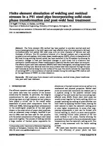
The axial stiffness of the three assembled Ilizarov configurations studied for both the experimental and FE method are shown in Fig. 7. The graph shows that the responses of the three fixator configurations are similar for both methods, with all responses linear. However, there is a consistent mean error of 10.1 per cent between the two methods (9.1 per cent, 11.3
Fig. 7 Comparison of the responses of the three configurations tested experimentally, in axial compression (see section 3.2), with the those analysed using the FE modelling system. The solid lines indicate the results from the mechanical testing, while the dashed lines indicate the FE results. The elastic ranges for the unstable, mid-stable, and full-stable configurations were 100 N, 150 N, and 200 N respectively, and only these load ranges are shown JEIM225 © IMechE 2007
Proc. IMechE Vol. 221 Part H: J. Engineering in Medicine
870
M Watson, K J Mathias, N Maffulli, D W L Hukins, and D E T Shepherd
per cent, and 9.8 per cent for the full-stable, midstable, and unstable configurations respectively).
4 DISCUSSION This study has described a computational method for predicting the mechanical response of any configuration of the Ilizarov external fixation system to assess the feasibility of using this method as an aid to preclinical planning. FE analysis was used to model each of the individual components (ring, threaded rod, and wire) of the Ilizarov system. Mechanical testing was then used to validate each of the FE models. Good agreement was found between the FE model and the mechanical testing for the individual components. A modular FE modelling system, using a master input file, was then developed where the prevalidated FE models of the individual components could be generated, positioned, and interconnected to replicate a range of fixator configurations. The stiffness predictions from the FE modelling system were consistently 10 per cent higher than the stiffness values obtained from the mechanical testing of the configurations. The study by Nielsen et al. [12] to investigate the different configurations for ankle external fixation found that the difference between their FE model and mechanical testing could be as high as 20 per cent. In this study, there are a number of possible reasons for the difference between the FE models and mechanical testing. The FE models used beam elements which do not take into account changes in the beam cross-section due to bending; this can lead to an overestimation in the bending stiffness. An earlier study [7] showed that there are considerable changes in wire tension when they are fixed to the ring, caused by compression of the wire between the connector bolt and the ring. These changes introduce a degree of uncertainty regarding the initial wire tensions to be used in the FE models and, hence, affect the computed fixator stiffness. Other potential reasons could be that there is local plastic deformation at the wire–bone interface or that the connection between the components of too rigid. The FE modelling system can be used to predict the characteristic response of various fixator configurations and clearly shows the relative changes in that response for variations in the number of components used. The plan is to develop a more userfriendly computer user interface to enable surgeons to select the required components and configuration, Proc. IMechE Vol. 221 Part H: J. Engineering in Medicine
without having to use a conventional FE package. The aim would be to have a computational model that can be solved within a few minutes to aid preclinical planning of which Ilizarov assembly configuration to use.
ACKNOWLEDGEMENTS The authors would like to thank The Sir Jules Thorn Charitable Trust for providing financial support and Smith & Nephew Surgical (Cambridge, UK) for supplying the materials used in this project.
REFERENCES 1 Ilizarov, G. A. Clinical application of the tensionstress effect for limb lengthening. Clin. Orthop. Relat. Res., 1990, 250, 8–26. 2 Watson, M. A., Mathias, K. J., and Maffulli, N. External ring fixators: an overview. Proc. Instn Mech. Engrs, Part H: J. Engineering in Medicine, 2000, 214, 459–470. 3 Watson, M. A., Mathias, K. J., Ashcroft, G. P., Maffulli, N., Hukins, D. W. L., and Shepherd, D. E. T. Wire tension in the Ilizarov system: accuracy of the wire-tensioning device. Proc. IMechE, Part H: J. Engineering in Medicine, 2005, 219, 355–359. 4 Lanyon, L. E. and Rubin, C. T. Static vs. dynamic loads as an influence on bone remodelling. J. Biomechanics, 1984, 17, 897–905. 5 Lindholm, R. V., Lindholm, T. S., Tiokkanen, S., and Leino, R. Effect of forced interfragmental movements on the healing of tibial fractures in rats. Acta Orthop. Scand., 1969, 40, 721–728. 6 Wolf, S., Janousek, A., Pfeil, J., Veith, W., Haas, F., Duda, G., and Claes, L. The effects of external mechanical stimulation on the healing of diaphyseal osteotomies fixed by external fixation. Clin. Biomechanics, 1998, 13, 359–364. 7 Watson, M. A., Mathias, K. J., Maffulli, N., and Hukins, D. W. L. The effect of clamping a tensioned wire: implications for the Ilizarov external fixation system. Proc. Instn Mech. Engrs, Part H: J. Engineering in Medicine 2003, 217, 91–98. 8 Baidya, K. P., Ramakrishna, S., Rahman, M., and Ritchie, A. Advanced textile composite ring for Ilizarov external fixator system. Proc. Instn Mech. Engrs, Part H: J. Engineering in Medicine, 2001, 215, 11–23. 9 Hillard, P. J., Harrison, A. J., and Atkins, R. M. The yielding of tensioned fine wires in the Ilizarov frame. Proc. Instn Mech. Engrs, Part H: J. Engineering in Medicine, 1998, 212, 37–47. JEIM225 © IMechE 2007
FE modelling of the Ilizarov external fixation system
10 Watson, M. A., Mathias, K. J., Maffulli, N., and Hukins, D. W. L. Yielding of the clamped wire in the Ilizarov external fixator. Proc. Instn Mech. Engrs, Part H: J. Engineering in Medicine, 2003, 217, 367–374. 11 Zhang, G. G. Geometric and material nonlinearity in tensioned wires of an external fixator. Clin. Biomechanics, 2004, 19, 513–518.
JEIM225 © IMechE 2007
871
12 Nielsen, J. K., Saltzman, C. L., and Brown, T. D. Determination of ankle external fixation stiffness by expedited interactive finite element analysis. J. Orthop. Res., 2005, 23, 1321–1328. 13 Benham, P. P. and Crawford, R. J. Mechanics of engineering materials, 1987 (John Wiley, New York).
Proc. IMechE Vol. 221 Part H: J. Engineering in Medicine