Finite element simulation of welding process has been wildly employed in engineering where welding deformation and residual stress are considered. One big ...
[溶接学会論文集 第 29 巻 第3号 p. 95s-99s (2011)]
Finite Element Simulation of Multi-pass Welding Process with Rezoning Technique㸨
by Hui HUANG**,Yao ZHAO*** and Hua YUAN** Finite element simulation of welding process has been wildly employed in engineering where welding deformation and residual stress are considered. One big problem during simulation is the severe demands of capacity of hard disk and computation time, especially for large structures with long weld length or multi-pass welding. To minimize the number of unknowns in finite element model, a rezoning technique is developed to simulate the multi-pass welding process. The local nonlinear zone around the current pass is modeled with a dense finite element mesh, while the region of other passes and nearby is modeled with a coarser mesh. Then the model is redefined layer by layer to represent the filling of the welding pass and the motion of the weld arc. The rezoning procedure is implemented using a reverse mapping algorithm with Newton method to solve the high order simultaneous equations. Three-dimensional finite element simulations with and without rezoning technique are performed to obtain transient temperature, welding deformation and residual stress. By comparing the results of the model, computational efficiency and accuracy of the proposed method is confirmed. Key Words:�
Finite element simulation, Multi-pass welding, Rezoning technique, Computational efficiency
1. Introduction
model and a moving heat source can more accurately simulate the welding problems. However, a complete three dimensional
Welding technology is widely used in shipbuilding, aerospace
thermal elastic-plastic analysis of multi-pass welding process is
industry, and bridge engineering for its excellent joining
usually difficult to accomplish because of the demanding
performance. One main problem in assembling is welding
computational effort. The model using the usual FEM would need
distortion which results in misalignment between assembly parts
very fine mesh in the heat affected zone. It is necessary to reduce
and increases fabrication costs. Furthermore, residual stress due
the unknowns of the finite element model according to the
to welding could affect structural reliability and local strength.
character of the welded zone.
Improper welding methods could cause brittle fracture, buckling
In the present study, a rezoning technique in three dimensional
and welding cracks, which are difficult to measure or observe
FEM analysis of multi-pass welding process is developed.
during welding. Therefore, it is essential to develop an effective
Welding deformation and residual stress of a plate made with
and efficient analysis method to estimate welding distortion and
low-temperature high-strength steel under multiple thermal cycles
residual stress in welding structures.
of multi-pass welding are investigated. The model is also
In the past decades, the thermal elastic-plastic finite element
simulated by the ordinary finite element method. By comparing
method has been widely employed in simulation of welding
the results of transient temperature, welding deformation, residual
deformation and residual stress for T-joint and butt welded plates.
stress and computational time, effectiveness and efficiency of the
Also, some models have been proposed to predict welding
proposed method is confirmed.
distortion or residual stress for multi-pass welding process. Ueda1) developed a thermal elastic-plastic FEM based on triangular
2. Rezoning Technique
element, and the welding stresses and strains in multi-pass welded butt joints of 150mm thick plate were investigated. Duranton2) proposed an adaptive meshing technique with constraint elements to decrease the computation costs when keeping good confidence in the results. Deng3) used a 2D axisymmetric model to predict welding stress in multi-pass butt-welded steel pipes, considering the influence of solid-state phase transformation. Compared with 2D finite element model, a 3D finite element � *Received: 2010.11.12 ** Graduate, Huazhong University of Science and Technology *** Professor, Huazhong University of Science and Technology
Due to the characteristic of welding problems, region in the heat affected zone of the weld piece is always in highly nonlinear state while most of the domain excluding the region is still in weakly nonlinear or even elastic state. Therefore, a dense mesh in the region and a coarse mesh in the domain can be adopted in thermal mechanical analysis to minimize degree of freedoms of the model. Then the region can be redefined according to the motion of the heat source, which will improve efficiency and ensure good accuracy in solution. Lindgren proposed automatic rezoning procedure in simulation of welding based on a graded
96s 研究論文 HUANG et al.: Finite Element Simulation of Multi-pass Welding Process with Rezoning Technique � � �� � � ◊✲ㄽᩥ
hexahedral element4). Brown developed rezoning and dynamic
Eq. 3 are high order simultaneous equations of ξ, η, and ζ. For
substructuring technique to perform finite element analysis on
each node of the new mesh, Eq. 3 is needed to solve normalized
5)
laser welding of plate with shell element .
coordinate. The authors employ Newton-Raphson method to find
There are two procedures in rezoning process. First, the
the approximate solution, and only a few iterations are sufficient
coordinates of the new mesh are obtained from the old one by
for convergence. Finally, the coordinate of node P can be obtained
calculating the normalized coordinates and substituting into
by interpolating the corresponding normalized coordinates
element shape function. Second, the solution variables are
through Eq.2.
mapped from the old mesh to the new one. 2.2 2.1 Nodes relocation
Solution Mapping
During the map solution procedure, the solution variables at
Generally, the occupied space of new mesh should be the same
the integration points of the old mesh are extrapolated to nodes of
as that of the old mesh, and exact location of each node in the
each element, and these values are averaged over all similar
new mesh are determined through normalized coordinates (Fig. 1).
elements abutting each node. According to the coordinate of each
We use the method proposed by Murti and Valliappan6) to detect
integration point in the new mesh, the element of the old mesh in
if the node is inside or outside an element. After the match
which the point lies is found. The location of each integration
relationship between the node in new mesh and the element in the
point is obtained with respect to the old mesh, and then the
old mesh is obtained, the normalized coordinates can be
variables are interpolated from the nodes of the old element to the
determined directly by a set of interpolation function for
integration points of the new element. The solution continues
iso-parametric element. Suppose that a node P locates in a known
with the mapping variables as the initial conditions.
element, and the interpolation function is shown as: 3. FEM simulation of multi-pass welded butt joint In this section, 3-D FEM analysis of multi-pass welded butt joint with rezoning technique is performed. The model used in this study is butt welded plate with length of 300mm, width 500mm and thickness of 30mm. Figure 2 shows the dimension of the welded butt joint, sequence of weld passes and detail of the groove. The material of the plate is EH36, which is a type of widely used steel in shipbuilding because of its excellent low-temperature high-strength performance. All of the nine passes are performed by gas metal welding with H08Mn2E as Fig. 1 A point in a hexahedral element and coordinate systems
weld filler. The welding condition of the model is given in Table
1 1 �1 � ξi ξ �1 � ηi η �1 � ζ i ζ �����������˄˅ 8
Ni
1.
The coordinate of node P can be transformed from normalized coordinate by the following formulas:
x
8
¦ N � ξˈηˈζ x i
i
i 1
y
8
¦ N � ξˈηˈζ y i
� 2
i
i 1
z
8
¦ N � ξˈηˈζ z i
i
Fig. 2 Shape and size of the multi-pass welding joint
i 1
As the nodal coordinates are known, the above formulas can be rewritten as [5]:
Numerical simulation of welding distortions and residual stresses needs to accurately take into account the interactions
a0 � a1ξ � a2 η � a3 ζ � a4 ξη � a5 ηζ � a6 ξζ � a7 ξηζ
0
b0 � b1ξ � b2 η � b3 ζ � b4 ξη � b5 ηζ � b6 ξζ � b7 ξηζ
0
c0 � c1ξ � c2 η � c3 ζ � c4 ξη � c5 ηζ � c6 ξζ � c7 ξηζ
0
� 3
Here, ai, bi, ci are functions of nodal coordinates (xi, yi, zi), thus
between heat transfer, mechanical fields and metallurgical transformations. In the present study, the phenomena such as arc, base metal/filler metal interactions, metallurgical transformation as well as fluid dynamics in the weld pool are not considered.
溶 接 学 会 論 文 集
第 29 巻(2011)第3号
97s �
In this study, the sequentially coupled thermal-mechanical
As the stress-strain effect on thermal analysis is neglected in
FEM simulation based on Abaqus code is employed. First, heat
the sequentially coupled thermal mechanical analysis, the same
transfer analysis is implemented to obtain temperature history.
finite element model in heat transfer analysis is employed here in
Secondly, mechanical analysis is performed by importing the
mechanical analysis, except for the element type and boundary
transient temperature as thermal load.
conditions. The applied boundary conditions in mechanical model Table1 Welding conditions of multi-pass butt joint
Pass
Current
Voltage
Speed
Heat input
Preheating/Inter-pas
Number
(A)
(V)
(mm/min)
(KJ/mm)
s temperature(Υ)
1
220
26
270
1.017
200
2
220
26
252
1.090
160~200
3
220
26
318
0.863
160~200
4
250
28
330
1.018
160~200
5
250
28
282
1.191
160~200
6
250
28
318
1.057
160~200
7
250
28
276
1.217
160~200
8
250
28
300
1.120
160~200
9
250
28
324
1.037
160~200
3.1 Heat transfer analysis
are shown in Fig. 3, which indicates that the restraint just
Transient temperature filed during the welding process can be
prevents the rigid body motion of the weld piece during welding. The temperature history obtained from heat transfer analysis is
obtained by the heat transfer analysis. The material properties of weld metal are assumed to be the same with that of base metal. According to the feature of gas metal arc welding, a combined surface and body flux heat source is adopted to simulate the heat of the arc and the molten metal droplets. The arc efficiency of the welding is assumed to be 0.80. 40% of the total heat input QT is given by surface flux and 60% by body flux. In this study, uniform flux distribution of both surface flux and body flux is assumed. Heat loss due to radiation and convection are considered together with a constant film coefficient of 30 W/m2/s/Υ. Latent heat is assumed to be 270J/g, with solidus and liquidus temperature 1465Υ and 1545Υ, respectively. User subroutine DFLUX is utilized to model heat input by surface and body flux, and the movement of the heat source.
input as thermal load in mechanical analysis. In the present study, phase transformation induced strain and work hardening is neglected. 3.3 FEM analysis with and without rezoning technique The finite element model in each welding pass with rezoning technique is shown in Fig. 4. In the rezoning model, the mesh changes after each welding pass, nodes relocation and solution mapping are performed between every two consecutive passes. The mesh of the full model without rezoning is the same with that of rezoning model in the last welding pass. The model change technique which enables the filling metal to activate/deactivate is adopted in the full model. Mesh division on the cross section of filling metal in each pass is the same in the two models, and element lengths in longitudinal direction are both 6mm. The node and element numbers of the first rezoning model are 8109 and 5950. The number of nodes is 19125, and that of elements is 16650 in the full model.
Fig.3 Boundary condition of the multi-pass welding model
3.2 Mechanical analysis
Fig. 4 Mesh of the rezoning model in each welding pass
98s 研究論文 HUANG et al.: Finite Element Simulation of Multi-pass Welding Process with Rezoning Technique � � �� � � ◊✲ㄽᩥ
Procedure of the thermal mechanical analysis with rezoning technique is shown in Table 2. The steps are carried out in a shell program which executes finite element analysis and user subroutines. The welding conditions and boundary restraint of rezoning model are the same with full model. Table2 Main steps of FEM analysis in rezoning model Step1 heat transfer analysis with the 1st mesh Step2 mechanical analysis with the 1st mesh; i=1 Step3 temperature field mapping from ith mesh to (i+1)th mesh Step4 heat transfer analysis with the (i+1)th mesh Fig. 6 Angular distortion in each welding pass
Step5 node coordinates relocation in (i+1)th mesh to occupy the same space in ith mesh
Angular distortion at the middle cross section of the plate
Step6 solution field mapping from ith mesh to (i+1)th mesh
normal to the weld line after each welding pass is shown in Fig. 6.
Step7 mechanical analysis with the (i+1)th mesh
Here, angular distortion is defined as the total changes of the
Step8 go to the next welding pass simulation (Step 3); i=i+1
angle between plate on the left side and plate on the right side. It is clear that the angular distortion depends on the location of the welding pass. If the welding pass is beneath the center of the
4. Simulated results and discussion
existed fusion zone, angular distortion will reduce; otherwise, it will grow.
4.1 Temperature history
Transverse shrinkage and angular distortion of the two
Generally, mechanical behavior and phase transformation are
different models after cooling are shown in Fig. 7. It can be seen
closely related to temperature during welding, thus temperature
that the distributions of welding deformations are quite uniform
history is significant to calculate welding deformation and
along the weld line. Simulated results of rezoning model agree
residual stress. Figure 5 shows temperature history at two specific
very well with the full model.
points in the full model and rezoning model. From this figure, it can be observed that the results of the models with and with rezoning technique agree well for the two points in transient time. Temperature on point 1 is higher than that on point 2 at any time since that the distance from the former to weld centerline is much closer than the latter one.
Fig. 7 Welding deformation of the multi-pass welding joint
4.3 Residual stresses Figure 8 shows Mises stress field on middle cross-section of the model with and without rezoning technique. The material in the fusion zone exhibits high stress level and most of the points Fig. 5 Temperature history of two points
have reached the initial yield strength. The difference of residual stress distributions between full model and rezoning model is
4.2 Welding distortions
very small.
溶 接 学 会 論 文 集
第 29 巻(2011)第3号
99s �
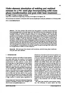
simulation time of the model with and without rezoning is 107.8h and 168.3h, respectively. In the present study, mesh coarsening has not been implemented. The relationship between coarsening criterion and solution accuracy is under investigation to gain more reduction in solution time. 5. Conclusions (a)
In this paper, a rezoning technique for three-dimensional thermal mechanical analysis is developed to simulate the multi-pass welding process. According to the calculated results of the model with and without rezoning technique, the following conclusions can be drawn: (1)Transient temperature, welding deformation and residual stress calculated in rezoning model agree very well with that of full model. (2)Computational time of the simulation is reduced by 36% with
(b) Fig.8 Comparison of Mises stress field on middle cross-section: (a)
rezoning technique for the studied model. Effectiveness and efficiency of the proposed method is confirmed.
without rezoning (b) with rezoning
Reference
4.4 Simulation time
Fig. 9 Comparison of simulation time for each welding pass
Computational time for each welding pass is shown in Fig. 9. It can be found that computational time increases by pass in the
1) Ueda Yukio, Eiji Takahashi, Keiji Fukuda, Keiji Nakacho: Transient and residual stresses in multi-pass welded butt joints of 15cm thick plate, J. Jpn. Weld. Soc., 44-5(1974), 466-474 2) P. Duranton, J. Devauxa, V. Robin, P. Gilles, J.M. Bergheau: 3D modelling of multipass welding of a 316L stainless steel pipe, J. Mater. Process. Technol., 153-154(2004), 457-463 3) D. Deng, H. Murakawa: Numerical simulation of temperature field and residual stress in multi-pass welds in stainless steel pipe and comparison with experimental measurements, Comput. Mater. Sci., 37-3 (2006), 269–277. 4) L. E. Lindgren, H. A .Haggblad, J. M. J. McDillb, a.s.oddy: Automatic remeshing for three-dimensional finite element simulation 0f welding, Comput. Methods Appl. Mech. Engrg., 147-3 (1997), 401–409. 5) S. B. Brown, H. Song: Finite Element Simulation of Welding of Large Structures, ASME J. Engrg. Ind., 114(1992), 441–451. 6) V. Murti, S. Valliappan: Numerical Inverse Isoparametric Mapping in Remeshing and Nodal Quantity Contouring, Comput. Struct., 22-6(1986), 1011-1021
rezoning model. This can be explained by the fact that the mesh scale becomes larger as the pass number increases. Total
� � � � � � � � � � � � � � � � � � � � � � � � � � � � � � � � � � � � � � � � � � �