Finite Field Arithmetic using Self-Assembly of DNA Tilings Rana Barua
[email protected]
Shantanu Das
[email protected] Indian Statistical Institute, 203 B.T.Road, Calcutta 700108, India
Abstract- Recently, it has been shown that the simple binary arithmetic and logical operations can be computed by the process of self assembly of DNA tiles, where artificially constructed 2-D DNA nanostructures called tiles attach with one-another to form complex superstructures, and in the process compute the result of these operations. We show how the DNA self assembly process can be used for computing finite field multiplication and addition. Our method can be used to efficiently execute multiple computation of finite field arithmetic, parallely and at very low cost.
1 Introduction There have many attempts at implementing the basic binary arithmetic and logical operations, using DNA computing. See, for example [GFB96], [GPZ97], [MLRS00] and [BM02]. But till date no attempts have been made to use DNA computing for finite field arithmetic. Finite field arithmetic has applications in cryptography, coding theory and other fields and it is of considerable interest to obtain a method for fast computation of finite field multiplication, in particular. By using DNA computing for finite field computation, we can parallely execute multiple computations at a very low cost. In the next section, we explain the process of ‘Self-Assembly of DNA Tilings’ and in section three, we show how we can use the self assembly process for computing finite field multiplication. We assume that the reader knows about the structure of DNA molecules and the basic biochemical operations that can be performed on them, such as annealing of two single strands, melting or breaking up of a double strand into single strands, extraction of a strand containing a particular sequence, ligation of DNA strands with the enzyme Ligase and duplication of DNA strands by the PCR reaction.
2 DNA Tiles and Self Assembly Since Adleman [Adl94] first demonstrated how DNA molecules can be used for computing in his seminal paper on solving the HPP using molecular computation, a number of different models for DNA computation has been proposed for solving a variety of computational problems. Most of these proposals implement the computation by per-
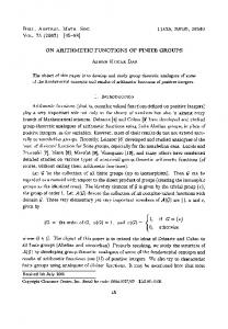
forming a series of biochemical reactions on a set of DNA molecules, which requires human intervention at each step. Thus, each of the steps requires a large amount of time as compared to computation steps of an electronic computer. Eric Winfree [Win98] first came up with the idea of computing using the automatic assembly of DNA nanostructures into complex super-structures. This idea was based on the mathematical concept of Wang tiles [Wan63]. The theory of Wang tiles says that if we have a set of square tiles with colored edges such that the tiles having edges of the same color facing each-other can join together, then the assembling of such tiles over a plane, can emulate the working of a Turing Machine. Winfree and Seeman [WLWS98] constructed some simple two-dimensional(2D) tiles using DNA strands, to demonstrate the feasibility of computing through the selfassembly of DNA tiles. These DNA tiles have unpaired ends of DNA strands sticking out and through these ‘sticky’ ends they can attach themselves with other tiles having the (Watson-Crick) complementary sticky end. Thus, these tiles can stick with one-another to assemble into complex superstructures and through this process they can compute in a way similar to Wang tiles. This process is called the “SelfAssembly of DNA Tilings”. Labean et al. [LYK+00] have come up with more complicated DNA tiles called Triple Crossover or TX tiles that contain three double helixes of DNA intertwined with one-another. These tiles are more stable and rigid, and can have upto six sticky ends through which they can attach with other tiles. We will look at three different types of TX tiles, which we will be using : • TAO tiles - These tiles have the structure shown in Figure 1(a). These tiles are formed by the annealing of four DNA single strands(shown in different colors) and they have four sticky ends at the four corners. Notice the strand (colored Green) passing from the bottom left to the top right of the tile. When TAO tiles join together diagonally (see Figure 1(b)), and we seal the joins by applying Ligase, we have a single DNA strand passing through the assembly from bottom left to top right (shown in bold). This property of the TAO tiles is important and will be made use of in our procedure. • TAE tiles - The structure of these tiles is as shown in Figure 2(a). Here we have six DNA strands forming the tile and there are six sticky ends, three on the left
(a)
Sticky ends
(a) TAO tile (b)
(c)
(b)
(d)
(c)
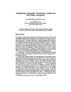
Figure 1: TAO tiles : (a) Structure of a single TAO tile. (b) Three TAO tiles join diagonally. (c) A single DNA strand runs through the three tiles. and three on the right. However if all the six sticky ends are not needed, then we can bend some of these into loops so that they are not used as sticky ends. • Rotated TX tiles - The tile in Figure 2(b) has only two sticky ends. These two sticky ends are so designed that when these attach with the sticky ends of two neighboring TAE tiles, the tile gets rotated (by an angle close to 90◦ ) relative to the plane of the TAE tiles. This rotated tile can fit in the small gap left in the center when four TAE tiles attach together. So, the TAE tiles and these rotated tiles can assemble to form a closely packed two-dimensional lattice structure as shown in Figure 2(d). Notice that when the rotated tile joins with two TAE tiles (Figure 2(c)), a single DNA strand (shown in bold) passes through the middle of the three tiles. These tiles can be constructed using a variety of possible nucleotide sequences. We can use different sequences to denote different symbols or values. For example, we can have one sequence denoting the value 0 and another sequence denoting the value 1. So tiles constructed using different sequences can store different values or symbols. We can also use the sticky ends of a tile to encode certain values or
Figure 2: TAE Tiles : (a) Structure of the TAE tile (b) Rotated TX tile (c) The rotated tile joins with two TAE tiles on its either side (d) The two types of tiles can assemble to form a compact lattice structure. symbols. The tile that attaches to this tile would have the complementary sticky end encoding the same value or symbol. In this way, we can pass information from one tile to its adjoining tile.
3 Finite Field Arithmetic A finite field is a field with a finite number of elements. For each prime p and each natural number n, there exists a unique finite field of pn elements denoted by GF (pn ). The elements of this field can be represented as polynomials in x, of degree less than n and having coefficients from Zp = {0, 1, ...p − 1}. We shall be concerned only with finite fields of the form GF (2n ), whose elements can be represented as binary numbers by taking the coefficients of xn−1 through x0 in their polynomial representation. The addition of two such elements of GF (2n ) is equivalent to the bit-wise XORing of the corresponding binary numbers. The multiplication operation in GF (2n ) is similar to polynomial multiplication except that if the result is of degree n or more, then we cut it down to less than n, by going modulo a fixed irreducible polynomial R, of degree n, in GF2 [x] (i.e. having coefficients from Z2 ). Now, let us see how this multiplication operation can be implemented using DNA tiles.
[y]
[y]
M
[y]
[z]
[y] [ r]
[y]
( z = x + y *r )
[ r]
[z]
[z]
[y]
[ r] [y]
[y]
[x]
[z] [ r]
[r n −1 ] [ bn −2 ] [r n −2 ]
[ bn −1 ]
[ bn −1 ]
[ b1 ]
...
[ bn −2 ]
[ r1]
[x]
[ b0 ] [ r 0]
[ b1 ]
B
[ b0 ]
(a)
1
M
1 [ bn −2 ]
[ b n−1 ] [ bn −1 ]
1
... ...
[ bn −2 ]
1
[ b2 ]
1
[ b1 ] [ b1 ]
[ b0 ]
: B1
[ b0 ]
:B
(b)
a_n−1
... a_2 3 b_n−1
M
a_1
2 b_n−1
M
a_0
1 b_n−1
M M
b_n−1
2 b_n−2 1 b_n−2
...
...
b_n−2
b_2
3 b_n−2
...
...
2 b_2
1 b_2
3 b_2
3 b_1
1 b_1 b_1
3 b_0 2 b_0
2 b_1 1 b_0 b_0
: B3 : B2 : B1 :B
(c)
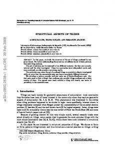
Figure 3: Implementing the basic step of computing B ∗ x(modulo R) from B: (a) Tiles representing the bits of B with other computation tiles hanging above. (b) The tiles assemble to form B ∗ x(modulo R) over B. (c) After multiple iterations of the basic step, we get each Bi . The tile structure for A is shown alongside. 3.1 Finite Field Multiplication Suppose we want to multiply two numbers A and B in GF (2n ) going modulo R, where A = (an−1 ∗ xn−1 + ... + a1 ∗ x + a0 ), B = (bn−1 ∗ xn−1 + ... + b1 ∗ x + b0 ), and R = (xn + rn−1 ∗ xn−1 + ... + r1 ∗ x + r0 ). Then the result of the multiplication, C is given by: X C= ai ∗ B ∗ xi (modulo R) or, C=
X i∈{0..n−1},ai =1
[B ∗ xi (modulo R)]
Note that, here the addition of the coefficients is done modulo 2 . We will denote (B ∗ xi (modulo R)) by Bi . The basic operation here, is computing (B ∗ x(modulo R)) from a given number B. We have B ∗ x(modulo R) = (bn−2 ∗ xn−1 + ... + b1 ∗ x2 + b0 ∗ x) +y ∗ (rn−1 ∗ xn−1 + ... + r1 ∗ x + r0 ) where y = bn−1 . So, the i-th bit, i.e. the coefficient of xi is given by (bi−1 + y ∗ ri ). Suppose we represent the number B as a string of DNA tiles, with each tile storing one bit of B. We can construct
such tiles which would assemble on top of this sequence of tiles to form another sequence of tiles representing the bits of B1 = B ∗ x(modulo R). This operation is shown in Figure 3. Here the labels on the sticky ends represent the information carried by them. We denote by [x] the nucleotide sequence encoding the value x and by [x] the complementary sequence. Notice the tiles (with six sticky ends) floating above the tile assembly for B. The sticky ends of these tiles are labeled by variables x,y,z and r of which x,y and r can take any value from {0, 1}. So we have eight different tiles of this type for various values of x,y and r. Only those tiles having compatible sticky ends could join together. Thus the tile which assembles on top of the two tiles storing bn−1 and bn−2 respectively, would have x = bn−2 , r = rn−1 and the same y value as the ‘M’ tile adjacent to it (which is equal to bn−1 ). This tile then computes the value x + y ∗ r = bn−2 + bn−1 ∗ rn−1 = b1n−1 , which is the (n-1)th bit of B1 (see Figure 3(b)). Thus, the tile representing the (i-1)th bit of B, passes the value of the bit to the i-th tile in the upper layer through the sticky end in its top left corner. The i-th bit tile in the upper layer gets the value of the (i-1)th bit, bi−1 and computes the value (bi−1 + y ∗ ri ) of the i-th bit of B1 . The value of y is passed to each tile from the tile on its left, through the sticky end in the middle. The value of y is initially obtained from the leftmost tile of the B sequence as bn−1 , and is passed to the upper layer through the tile labeled ‘M’. On repeating this simple operation, we can get B2 = B ∗ x2 (modulo R), on top of B1 and B3 = B ∗ x3 (modulo R) on top of B2 and so on. Thus, we would have an assembly of multiple layers of DNA tiles, where the i-th row would represent Bi . Now we only have to perform an addition of all such Bi ’s for which ai = 1. For this we maintain a partial sum, Si at each layer,i such that S−1 = 0 and Si = Si−1 + ai ∗ Bi The bits of Si−1 are passed to the i-th layer through the bottom left sticky end of the tiles, along with the r value. But, in order to calculate the corresponding bits of Si , the value of ai should be available. The solution is to construct a diagonal tile assembly representing the bits of A (as shown in Figure 3(c)), and allow this to join to the left side of our earlier assembly such that the tile storing the i-th bit of A is attached to the i-th row. The value of ai would be passed along the row, through the sticky ends in the middle, along with the y value. This is done using the tiles shown in Figure 4. Here, H(x),G(w, r) and Q(y, m) denote nucleotide sequences encoding the value x, w and r, and y and m respectively.
m0
m1
V(x) ms
M0
m1 M1
Q(y,x)
(b)
H(y)
m1 (a) G(w’,r)
H(z)
z=x+y*r [z]
Q(y,m)
Q(y,m)
w’ = w + m*z x, y, m, r, w in {0,1}
H(x)
G(w,r)
(c)
Q(y,m)
Q(y,m) H(0) (d)
H(0)
ZE (0)
H(0) H(0)
Ze
(0) (0)
(e)
Z2
Z1
Figure 4: DNA Tiles required for computing finite field multiplication. The tile shown in (d) is a rotated TX tile and all the other tiles are TAE tiles. The tile shown in Figure 4(c) is the computation tile which computes the bits of Bi as explained before. But, it also computes the partial sum bits as w0 , using the value of partial sum bit w that it receives from the lower layer through the sticky end at its bottom left. The value of y and m = ai are passed from one tile to another in the same row, using the bridge tiles shown in Figure 4(d). The value of ai is initially passed to the layer representing Bi , through the tile labeled ‘M1’ shown in Figure 4(b), to which the ith bit tile of A would attach. Finally the tiles shown in Figure 4(e) are used for adding a zero at the end, while computing Bi from Bi−1 . Vs res
Qs
S0
m1
Ze
H(x)
Qs
E
Qs
Qs
Qs
Qs
D(w,r) G(w,r)
H(x)
x,w,r in {0,1}
Figure 5: Output Tiles: These tiles are used to store the result of the computation The tile structure for B would be as shown in Figure 6 and this consists of TAE tiles with rotated TX tiles in be-
S0
D(b3,r3)
D(b2,r2)
D(b1,r1)
TAE Tile
H(b0)
G(0,r0)
H(b1)
G(0,r1)
H(b2)
G(0,r2)
H(b3)
G(0,r3)
H(0)
ms
Z1
D(b0,r0)
Z2 E
Rotated TX Tile
Figure 6: Input Tiles-II: DNA tile structure representing the 4-bit number B = (b3, b2, b1, b0) tween. Each tile has two sticky ends at its top, the left one encoding the value of the bit bi stored in the tile and the right one encoding the value 0 as the i-th bit of the initial partial sum S−1 , along with the value of ri (the i-th bit of R). So, the ri value is stored along with each bit bi of B. Two special tiles encoding the symbols ‘S0’ and ‘E’ respectively, are used to denote the start and the end of number. Note that, a single strand of DNA (shown in Green), passes through each tile of B and thus contains an encoding D(bi , ri ) of each bit bi of B. This single strand of DNA can be used to represent the number B. S0 Vs
D(a3,r3)
V(a3)
D(a2,r2)
V(a2)
D(a1,r1)
V(a1)
D(a0,r0)
V(a0)
E m0
Figure 7: Input Tiles-I : DNA representation of the 4-bit number A = (a3, a2, a1, a0) Figure 7 shows the tile structure for A. Here each tile has only one sticky end and it encodes the value of the bit stored in the tile. This tile structure consists of TAO tiles and as explained earlier, a single strand of DNA passes diagonally through the structure. This single strand passes through each of the tiles and encodes the bit value stored in each tile. Note that this encoding is the same as that used for representing the number B.(Here, the r-bits are retained only for uniformity, and they are not used in the computation). So, we have a unique representation for each number in GF (2n ) as a single stranded DNA molecule as shown in Figure 8. This is the form in which we would be storing all numbers, in our system. 3.2 An Example Let us now look at an example computation of finite field multiplication using our method. For simplicity we will
consider four bit numbers, or elements of GF (24 ). We take, A = x3 + x or, (1010) B = x3 + x2 + 1 or, (1101) and, R = x4 + x + 1 The numbers A and B, which are in the form of ssDNA (as in Figure 8) are converted to appropriate tile structures as in Figure 7 and Figure 6 respectively. Now, we add the other tiles (Figure 4) required for computation and allow them to anneal together. Figure 9(a) shows the initial stage of the computation while Figure 9(b) shows the pre-final stage of the computation when the last layer representing B3 has been computed. At this stage the sticky ends of the final layer tiles contain the result of the multiplication. In order to output the result in the form of a DNA strand, we require some output tiles of the form shown in Figure 5. On adding these tiles, and allowing them to anneal, we get the the final tile assembly as shown in Figure 9(c). On adding Ligase to seal the bonds, we will have a single strand of DNA passing through the tiles in the final output layer, that encodes the result of the computation. This single strand begins with the unique nucleotide sequence labeled ‘res’. To extract the ssDNA representing the result, we first break up the hydrogen bonds to decompose the tile assembly into DNA single strands and then do an extraction operation using the nucleotide sequence complementary to the ‘res’ sequence. The ssDNA obtained as the result of the computation would be in the same format (Figure 8) as the original inputs, and thus can be used as the input in further computations. 3.3 Finite Field Addition The finite field addition operation can be implemented in a similar way. Figure 10 shows the addition of two fourbit numbers A = (a3, a2, a1, a0) and B = (b3, b2, b1, b0). The number A would be represented by the tile structure shown in the top while the number B would be represented by a similar tile structure with sticky ends at the top of the tiles instead of the bottom. The blue-colored tiles shown in the figure form the result, C = (c3, c2, c1, c0) of the
S0
D(an−1 , r n−1 )
...
D(a1 , r1 )
D(a0 ,r0 )
E
Figure 8: ssDNA representation of the n-bit number A = (an−1 ...a1 a0 ) computation. Note that a single strand encoding the result passes through these tiles, and contains the ‘res’ sequence in the front. This strand can be extracted as before and used in further computations.
4 Implementation Issues To implement our method of finite field arithmetic, we have to find suitable nucleotide sequences for encoding all the symbols used in our computation, such as S0, E, V(0), V(1), D(0,0), D(0,1) etc. and we have to ensure that these sequences (and their complementary sequences) are sufficiently different from each-other. The other issues to be considered while implementing our method are : • Constructing the input DNA strands - The input DNA strands of the form shown in Figure 8 consists of the nucleotide sequence S0 followed by D(0, ri ) (if ith bit is zero) or, D(1, ri ) (if i-th bit is 1) for each i ∈ {n − 1, ..0}, finally followed by the sequence E (here ri ’s are the bits of the irreducible polynomial R). Between the sequences encoding two consecutive bits we have another nucleotide sequence, say SJ which will be required for forming the tile structure. Now, we can initially construct all possible numbers by joining together the different nucleotide sequences forming the numbers. We will store multiple copies of all the numbers as a data pool and at the time of executing a computation we will extract the DNA strand encoding the particular number to be used as input. • Converting the input ssDNA to tiles - The DNA tiles are formed by annealing together of the constituent single strands making up the tile. For example, a TAO tile consists of four nucleotide strands as explained before (Figure 1). For converting the input ssDNA into the TAO tile structure (Figure 7), we just have to mix the other three constituent strands for each of the tiles in the structure and allow them to anneal to the long input strand. The input strand will act as a scaffold to which the other strands will join forming the required tile structure. Similarly the other tile structure (Figure 6) can be constructed. • Constructing the computation tiles & output tiles Figure 4 and Figure 5 show the various computation and output tiles that have to be constructed. These tiles are constructed by first constructing the constituent strands (by the standard method) and then allowing them to anneal together to form the tile. Some
copies of these strands would be kept in a storage pool and whenever new tiles are required (for starting a computation), these would be created from the contituent strands taken from the storage pool. The strands in the storage pool may be duplicated periodically, using PCR. • Executing the Computation - The computation can be executed in a small chamber or cell containing the computation tiles, into which the input tile assemblies are added. The temperature and other conditions of the chamber would be adjusted by external controls, to allow for the annealing of complementary sticky ends. We can have multiple such chambers for parallely executing multiple such computations. At the end of each computation, Ligase is added to seal the joints and then, the temperature of the chamber is increased to break up the tile structure into single strands. The result strand is then extracted by affinity purification using the complement of the ‘res’ sequence. The ‘res’ nucleotide sequence would contain the site of a restriction enzyme at the end, so that the ‘res’ portion can be cut-off from the result strand by applying the appropriate restriction enzyme. As a result we will get an ssDNA of the same format as the input strands. This strand can then, be used in further computations. • Reading the result - To output the result of the computation we would use a modification of the standard sequence-reading operation that uses a combination of PCR and gel electrophoresis. Using PCR we can obtain strands of different lengths representing the positions of each of D(0, 0), D(0, 1), D(1, 0), and D(1, 1) in the result strand. We can use dyes of two colors - one for strands representing the positions of D(0, 0) and D(0, 1) (i.e positions having bit-value 0), and the other for those representing the positions of D(1, 0) and D(1, 1) (i.e positions having bit-value 1), and then perform a single gel electrophoresis operation on these colored strands to get the positions of zero’s and the one’s in the original result strand.
5 Conclusion Our method for implementing finite field computation, extends the technique used by LaBean et al.[LWR99] for binary addition and XOR. The advantage of our method, is
H(0)
m1 V(0)
Q(1,1)
Q(0,0)
M1
Q(0,0)
Q(0,0)
m1
G(0,1) Q(1,1)
[0]
G(0,1)
H(0)
S0
H(1) H(1)
G(0,1)
Vs Q(0,0)
D(1,0)
Q(0,0)
[1]
V(1)
Q(1,0)
Q(1,0)
G(0,1)
D(0,0) V(0)
H(1)
D(1,1)
M0
D(1,0)
D(1,0)
S0
D(0,1)
Z2
Z1
H(1)
G(0,1)
H(0)
G(0,1)
H(1)
m1
H(1)
H(0)
V(0)
G(0,0)
D(0,1) E
G(0,0)
V(1)
D(1,1)
E
(a) Initial stage
Qs
Vs
res
Qs
S0
Qs
Qs
Qs
S0
H(0)
G(0,0)
(0)
D(1,0)
G(1,1)
(0) (0)
D(1,0)
H(0)
(1) (1)
(0) (0) (0) (0)
(1)
H(1)
(0)
(0)
(1)
M1 M0
(0) (1)
M1
D(0,1) E
G(1,0)
(0)
M1
D(1,1)
H(0)
M1
D(0,0)
Ze H(1)
G(1,0)
Vs m1
D(1,0)
E
Qs
D(1,0)
H(0)
m1
S0
Qs
Qs
G(1,1)
(0)
ZE
(1) (1)
(0)
(1) (1) (1) (1)
Ze
H(0)
(0) (0) (0)
D(0,1)
D(1,1)
E
(b) Pre−final stage
S0 D(1,0) D(0,0) D(1,1) D(0,1) E
(0) (0)
M1
(1) (1)
S0
D(1,0)
S0
M1
M1 M1
M0
res
(0)
(0) (0)
(0) (0) D(1,0)
D(1,1)
(1)
(0)
(1) D(1,0)
D(0,0)
(0) (1)
(1) (1)
D(0,1)
D(1,1)
(0) D(1,1)
ZE (0)
(0)
E
(c) Final stage Figure 9: Example Computation of 4-bit finite field multiplication
E
m0
S0
Vs
Vs
ms res
D(a3,0) G(a3,0) Vs
ms
Qs
Vs
res AD1
S0
Vs G(a3,0)
Vs G(a3,0)
D(a2,0)
D(b2,0)
Qs
D(a1,1) D(c1,1)
D(c2,0) D(b3,0)
Ze
Vs
Ze
E
Vs
G(x,r)
D(a3,0)
E
Vs
( z = x XOR y )
Qs
D(z, r)
D(c3,0) S0
D(a0,1)
G(y,r)
Vs
S0
AD1 ADD
G(a3,0)
D(a1,1)
Vs
Qs
S0
Vs
D(a2,0)
Ze
E
D(c0,1) D(b1,1)
E
D(a0,1)
D(b0,1)
E
Figure 10: Finite field addition of two 4-bit numbers A=(a3,a2,a1,a0) and B=(b3,b2,b1,b0). that once the initial strands are constructed, each multiplication operation is computed very fast through the selfassembly process and the output of one computation can be directly passed as input to another computation. The only time consuming operation is the reading of the output. As this would be done only once at the end of a series of computations (or, a program), this would not much affect the total computation time. To conclude, we look at the possible errors that can occur during our process of computation. The possible sources of errors are, either an error in constructing the tiles, or an erroneous binding of tiles. The former error can be minimized by appropriately choosing the nucleotide sequences used in the tile. LaBean et al.[LWR99] have shown that the nucleotide sequences of the constituent strands forming a tile, can be chosen in such a way that, whenever these strands are allowed to anneal, they almost always form the desired tile structure, without forming other unwanted structures. The other possible error is when a tile attaches to a site meant for some other tile. Now, if we choose the sticky end sequences encoding different symbols to be sufficiently different from each other and their complement, then only matching sticky ends will anneal together. In that case, a wrong tile attaching to a site is still possible if a tile with three sticky ends uses only two of them to attach to the site, with the third sticky ends remaining unmatched i.e. hanging. If that happens then the resulting structure will be highly unstable relative to the stable and compact 2D structure that we get for all correct bindings. Thus, the probability of such a mismatch occurring is very low.
[BM02] R. Barua and J. Misra, “Binary arithmetic for DNA computers”, 8th International Workshop on DNABased Computers(DNA8), Sapporo, Japan, 2002. [GFB96] F. Guarneiri, M. Fliss and C. Bancroft, “Making DNA Add”, Science 273:220-223, 1996. [GPZ97] V. Gupta, S. Parthasarathy and M.J. Zaki, “Arithmetic and Logic Operations with DNA”, Proc. of 3rd DIMACS Workshop on DNA Based Computers, U. Penn, 212-220, 1997. [MLRS00] C. Mao, T.H. LaBean, J.H. Reif and N.C. Seeman, “Logical Computation using Algorithmic SelfAssembly of DNA Triple-Crossover Molecules”, Nature 407: 493-496, 2000. [LWR99] T.H. LaBean, E. Winfree, J.H. Reif, “Experimental Progress in Computation by Self-Assembly of DNA Tilings”, 5th International Meeting on DNA Based Computers(DNA5), MIT, Cambridge, M.A., June 1999. [LYK+00] T.H. LaBean, H. Yan, J. Kopatsch, F. Liu, E. Winfree, J.H. Reif and N.C. Seeman, “Construction, Analysis, Ligation, and Self-Assembly of DNA Triple Crossover Complexes”, J.Am.Chem.Soc. 122:18481860, 2000. [Wan63] H. Wang, “Dominoes and the AEA case of the Decision Problem”, In Proc. Symposion on Mathematical Theory of Automata, pp. 23-55, Polytechnic Press, New York, 1963.
Bibliography
[Win98] E. Winfree, “Algorithmic self-assembly of DNA”, Ph.D.thesis at California Institute of Technology, August 1998.
[Adl94] L. Adleman, “Molecular computation of solutions to combinatorial problems”, Science, 266:1021-1024, Nov.11, 1994.
[WLWS98] E. Winfree, F. Liu, L. Wenzler and N.C. Seeman, “Design and self-assembly of two-dimensional DNA crystals”, Nature 394:539-544, Aug.6, 1998.