and w defines the generalized intrinsic shape parameter associated with V. Given an object of interest in an image, fitting the ASM model to the object involves ...
LPSM: Fitting Shape Model by Linear Programming Jilin Tu, Brandon Laflen, Xiaoming Liu, Musodiq Bello, Jens Rittscher and Peter Tu Visualization and Computer Vision Lab, General Electric, 1 Research Circle, Niskayuna, NY, USA {tujilin, laflenb, liux, bello, rittche, tu}@crd.ge.com
Abstract— We propose a shape model fitting algorithm that uses linear programming optimization. Most shape model fitting approaches (such as ASM, AAM) are based on gradientdescent-like local search optimization and usually suffer from local minima. In contrast, linear programming (LP) techniques achieve globally optimal solution for linear problems. In [1], a linear programming scheme based on successive convexification was proposed for matching static object shape in images among cluttered background and achieved very good performance. In this paper, we rigorously derive the linear formulation of the shape model fitting problem in the LP scheme and propose an LP shape model fitting algorithm (LPSM). In the experiments, we compared the performance of our LPSM with the LP graph matching algorithm(LPGM), ASM, and a CONDENSATION based ASM algorithm on a test set of PUT database. The experiments show that LPSM can achieve higher shape fitting accuracy. We also evaluated its performance on the fitting of some real world face images collected from internet . The results show that LPSM can handle various appearance outliers and can avoid local minima problem very well, as the fitting is carried out by LP optimization with l1 norm robust cost function.
I. I NTRODUCTION Given pictures of objects of the same category (i.e., human faces) with manually labeled landmarks as training data, Cootes proposed to learn the intrinsic shape and appearance variations as statistics and proposed the Active Shape Model (ASM) [2] and Active Appearance Model(AAM) [3]. The ASM/AAM approaches received wide attention in the computer vision community and were extended in many ways for different applications.In brief summary, the shape model has been extended from PCA [2] to Kernel PCA [4], and to a hierarchical bayesian model [5]. The appearance likelihood model of ASM has been extended from the simple Gaussian distribution of normalized pixel values [2] to Mixture of Gaussians with discriminative features computed from image patch centering at the landmarks ( Gabor wavelet [6],Ranking-Boost [7], Fisher-boost [8], etc.). The fitting algorithm of the ASM models to the object in the image was extended from coarse-to-fine iterative optimization process constrained by PCA shape subspace [2] to Expectation-Maximization (EM) optimization [9] and sampling based approaches [5][8][10] in a Bayesian inference framework. These approaches are based on gradient descent optimization in essence and suffer from problems with local This work was supported by award #2007-DE-BX-K191 from the National Institute of Justice, Office of Justice Programs, US Department of Justice. The opinions, findings, and conclusions or recommendations expressed in this publication are those of the authors and do not necessarily reflect the views of the Department of Justice.
minima. Due to the high dimensionality of the image space and the highly cluttered image background, these approaches depend heavily on good initialization. On the other hand, if we assume the object of interest do not have large intrinsic shape variation, or the shape variations can be characterized by some heuristic constraints, we can characterize the object shape by a graph template, and graph matching techniques can be employed to localize the object in a testing image. Graph matching has a rich history in computer vision and pattern recognition applications, dating back to the 1970’s [11]. Recently, in [12], Jiang and Yu formulated the graph matching problem as a linear programming (LP) framework. The optimization was carried out in a successive convexification scheme. By successively convexifying the matching cost surface in a coarse to fine manner, the fitting of the template to the target image can be solved after it is formulated as a linear programming problem. As linear programming can achieve globally optimal solutions to linear objective functions subject to linear constraints, Jiang and Yu demonstrated that their graph matching algorithm can achieve good localization performance in images with a large search range and with cluttered background. In this paper, we extend the LP graph matching (LPGM) technique in [12] to the object shape model fitting problem, and propose an LP shape model (LPSM) fitting algorithm. By incorporating a shape subspace model that spans the object shape variations, LPSM can achieve better shape fitting accuracy for the objects of a category with non-rigid shape deformations (i.e., human faces). By doing the optimization in an LP framework, LPSM can find globally optimal solution without relying on a good model initialization. More specifically, we summarize the novelties of our paper as follows: 1) We rigorously derive the linear formulation of the shape model fitting problem, and propose to replace the gradient descent or other local optimization techniques) in ASM with a globally optimal linear programming (LP) technique, after the shape fitting problem is formulated in the LP framework. The proposed algorithm therefore does not rely on good model parameter initialization. 2) In order to get more accurate estimation of the scale and orientation of the shape model, we propose a refined unit circle linearization procedure by extending the LP framework in [12]. 3) For implementation, we also proposed to approximate the joint distribution of the allowable shape instances from real world by convex hulls in a number of 3 dimensional most correlated
subspaces to refine the search space in the LP formulation. 4) We propose to model the landmark appearance likelihood in Maximal Rejection Classifier[13] subspace that captures the discriminability between the appearances at the landmarks and its surrounding areas. In section 2, we briefly summarizes the shape fitting problem in ASM literatures, and the graph matching problem in LP framework. Based on the analysis in section 2, we formulate the shape model fitting problem in LP framework in section 3, and provide linearization solutions for the refined estimation of the scale and rotation parameters. We then describe our MRC appearance likelihood model and provide some implementation details. We show the experimental results in section 4, and finally provide a discussion on the strengths of our work and some future works in section 5. II. M ATHEMATICAL F ORMULATION A. Shape model fitting As shown in [2], a set of corresponding points on object ~ = [x1 , y1 , x2 , y2 , ..., xN , yN ]0 can be shapes in the form S ~= captured by a PCA model after Procrustes analysis, i.e., S ¯ ¯ ~ ~ ~ S + U~c. where S is the intrinsic shape, S is the mean of the shapes, U is the shape basis matrix that characterizes the intrinsic shape variations, and ~c is the intrinsic shape parameter. In [14], the extrinsic transformation of the object shape (in terms of scaling factor s, rotation angle θ and translation t = [tx , ty ]0 ) is modeled as a global similarity transformation. Consider the landmark Si = [xi , yi ]0 on img ~ the intrinsic shape = � � S, the similarity transform is Si 1+a −b Si +t, i = 1, ..., N, where a = s cos θ−1 b 1+a and b = s sin θ. By rearranging this equation, the 2D ~ can be similarity transformation for the object shape S ~ img = S ~ + [~g1 , ~g2 , ~g3 , ~g4 ]d~ = formulated in a linear form: S ~ where ~g1 = [x1 , y1 , x2 , y2 , ..., xN , yN ]0 = S, ~ + G(S) ~ d, ~ S 0 ~ ~g2 = [−y1 , x1 , −y2 , x2 , ..., −yN , xN ] = RS(R � is a diag� 0 −1 onal block matrix with diagonal block being ), 1 0 0 0 ~g3 = [1, 0, 1, 0, ..., 1, 0] , ~g4 = [0, 1, 0, 1, ..., 0, 1] and d = ~ = [S, ~ RS, ~ ~g3 , ~g4 ]. And [a, b, tx , ty ]0 . Here we denote G(S) further derivation yields ~ img = S ~¯ + G(S) ~¯ d~ + U~c(1 + a) + RU~cb. S (1) ~¯ 0 U = 0 because the training According to [15][14], G(S) shape data is normalized by generalized Procrustes analysis. ~¯ and G(S) ~¯ 0 U = 0, it is Given the properties of R, G(S), ¯ ~ 0 RU = 0. straight forward to prove that G(S) Therefore, by defining V as the gram-schmidt orthogonalization of [U, RU] (in practice, we can let V ≈ U as we observe most of the shape variations represented in RU � can � d~ ¯ ¯ img ~ ~ ~ be captured by U), we have S = S + [G(S), V] w ~ ~¯ ⊥ V, d~ defines the global affine transformation where G(S) and w ~ defines the generalized intrinsic shape parameter associated with V.
Given an object of interest in an image, fitting the ASM model to the object involves minimizing the following cost function � � ~ ~ img − S ~¯ − [G(S), ~¯ V] d k. Cshape = kS (2) w ~ To ensure that the similarity transformation is Euclidean, we optimize the cost function with the constraint (a + 1)2 + b2 = s2 , (s > 0). B. Graph matching by linear programming In [1], the matching of two sets of points is formulated as a linear programming problem. Given a point set M = {p}, we can pre-define a set of pair-wise neighboring model points N = {p, q|p, q ∈ M}. Let f (p) be the target point in a query image matched to the model point p, the objective function for minimizing the matching cost is defined as follows X X min{ c(p, f (p)) + λ g(p, q, f (p), f (q))}, (3) f
p∈M
{p,q}∈N
where c() is the feature matching cost, which is minimized when p and f (p) match correctly, and g() is the spatial matching cost that can be minimized when the pairwise spatial connection (p, q) in the model is similar to that of (f (p), f (q)) in the target image. In particular, we can define g(p, q, f (p), f (q)) = ksR(p − q) − (f (p) − f (q))k where s and R define the scaling and rotation respectively. In [12], the rotation and scaling parameters are utilized in two separate terms applied to the model points and the target points respectively, and a matrix formulation is derived as follows min �(X, s, R) = tr(C 0 X) + λ|EM R − sEXT |,
(4)
subject to X1nt = 1nm , X ∈ {0, 1}nm ×nt , s > 0 and R R = I, where the following terms are defined: · Xnm ×nt is a binary assignment matrix. X(i, j) = 1 defines a match between the i-th model point and the jth target point. X1nt = 1nm indicates each model point matches to only one target point. · s is the global scaling parameter. · R is the 2D rotation parameter. · Mnm ×2 is the matrix for the 2D model points. · Tnt ×2 is the matrix for the candidate 2D target points. · Cnm ×nt is the feature matching cost matrix, where C(i, j) is the matching cost between the i-th model point and the j-th target point. · Ene ×nm defines the graph edges of the neighboring model points. For edge e which connects the model point i to the point j, we have E(e, i) = 1 and E(e, j) = −1. 1 ≤ e ≤ ne = |N |. To remove the l1 norm in Eq. 4, the cost function can be further linearized [12] as 0
min �(X, s, R, Y, Z) = tr(C 0 X) + λ10ne (Y + Z)12
(5)
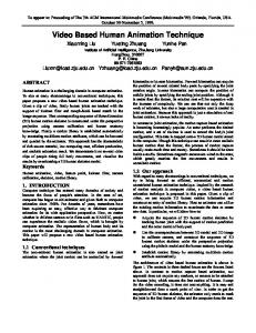
subject to Y − Z = EM R − sEXT , Y ≥ 0,Z ≥ 0. As illustrated in Figure 1-(a), the rotation matrix R = [u, −v; v, u] is linearized by approximating the unit normal
v
u2 + v 2 = 1
v
u 2 + v 2 = s2
+ (u+ 1 , v1 ) + + a+ 2 u + b2 v = c2
(uo1 , v1o ) ∆θ θˆ1
u
(ˆ u1 , vˆ1 ) u − (u− 1 , v1 )
u ± v = ±1
u ± v = ±s Iteration1
(a)
(b)
Fig. 1. The approximation of rotation on a unit circle. (a) The four line segments approximation in [1] ; (b) The finer line segment approximation of the unit circle at iteration 1.
constraint u2 + v 2 = 1 with four line segment u ± v = ±1, |u| ≤ 1, |v| ≤ 1. The scaling parameter s is quantized into ns variables, i.e., 0 < s1 < s2 < ... < sns , so that the assignment matrices P {Xl } are introduced, one for each scale nl , X = l Xl . Since the binary assignment matrix is relaxed to permit real values in [0, 1], the formulation is able to approximate any s ∈ [s1 , sns ]. In [1] and [12], the linearization of the problem makes it possible to find the globally optimal model fit (for the re-formulated linear system) amid the clutter in the image.
Approximating the unit circle by four line segment introduces inaccuracy. For example, the magnitude of the rotation matrix represented uv in the line segment may be biased to cos( π4 ) = 0.707 < 1 in the worst situation. This causes an unnecessary bias to the estimation of the rotation and scaling factor. We propose to refine the approximation of the unit circle as the successive convexification is moving toward finer resolution. We define the rotation and scaling by the circle u2 + v 2 = s2 in the uv space, as shown in Fig. 1-(b). Assuming the optimal solution is found at (ˆ u1 , vˆ1 ) on the line segment u + v = s in iteration 1, the rotation angle can be computed as θˆ1 = tan−1 uvˆˆ11 . Assuming the angle estimation error is within the range of ∆θ , two line segments that approximate the arc within θˆ1 ± ∆θ on the circle can be ± defined by the ending points (uo1 , v1o ) and (u± 1 , v1 ) with uo1 = s cos(θˆ1 ), v o = s sin(θˆ1 ), 1
ˆ u± 1 = s cos(θ1 ± ∆θ), ± v = s sin(θˆ1 ± ∆θ). 1
(7)
As successive convexfication is moving toward finer resolution, we can assume the error range for the angle estimation ∆θ is gradually decreasing. The resulting line segments ± ± a± i u + bi v = ci provide finer approximation to the circle 2 2 2 u + v = s in the uv space, which can be beneficial to the linear programming defined in Eq. 6.
III. S HAPE M ODEL F ITTING BY L INEAR P ROGRAMMING Based on Eq. 2 and Eq. 4, we can formulate shape model fitting in an LP framework by minimizing ~ w) �(X, d, ~
= tr(C 0 X) + ~¯ + [G, V] λ|EΩ(S
�
d~ w ~
� ) − EXT | (6)
subject to X1nt = 1nm , X ∈ {0, 1}nm ×nt , and (d~1 + 1)2 + d~22 = s2 (s > 0), where X,C,E, T , have been defined ~¯ G, V, d~ and w in Eq. 4; S, ~ defines the shape model in Eq. 2, and Ω(·) is a matrix the � operator that reshapes �0 x x . . . x 1 2 n vector [x1 , y1 , ...xn , yn ]0 into . As the y1 y2 . . . yn constraint on the scaling and rotation parameters is nonlinear, we propose our linearization procedure as follows. A. Linearization Noticing that the task of object shape fitting is usually carried out after object detection, and the input image can be normalized based on an approximate estimation of the object location, scale and orientation, we therefore do not put efforts in making LPSM scale and rotation invariant. Given the assumption, we simply assume the scaling factor is in a range of [0.7 1.3]. We also assume the object orientation angle is in a range of [−30o + 30o ]. In [12], the rotation matrix is modeled by variable u,v satisfying u ± v = ±1, |u| ≤ 1, |v| ≤ 1. Four programs for Eq. 5 are carried out, one for each line segment as the constraint in the uv space. The optimal solution is obtained by the one that achieves the lowest matching cost at the converging stage.
B. The algorithm We summarize the linear programming formulation of the shape model fitting problem at iteration i as follows: ~ w) min �(X, d, ~ = tr(C 0 X) + λe 10ne (Y + Z)12
(8)
subject to ~¯ + [G, V] · Y − Z = EΩ(S
�
d w
� ) − EXT , Y, Z ≥ 0;
· X1nt = 1nm , X ∈ {0, 1}nm ×nt . ± ± · u = d1 − 1, v = d2 , a± i u + bi v = ci , 0.7 < s < 1.3; ± ± · u ∈ [uoi , ui ], v ∈ [vio , vi ], |w| ≤ 3σw ;
where σw is the standard deviation of the intrinsic shape parameters. As the translation of the model does not affect the cost, we set the exterior parameter d3 = d4 = 0. At each iteration, two linear programs are generated with ± ± line segment parameter a± i , bi , ci computed according to Eq. 7, given the estimation of rotation angle θˆ and assumed estimation error range ∆θ at the previous iteration. Therefore, taking advantage of the successive convexification technique in [1], the LPSM fitting algorithm is summarized in Algorithm 1. IV. I MPLEMENTATION The LPSM is implemented with a successive convexification scheme described in detail in [1]. In the first iteration, we let θˆ = 0 and ∆θ = 30o . As the trust regions are getting smaller, we reduce the angle estimation range ∆θ π ,(M > 6), with M gradually increasing. by M
Algorithm 1: LPSM fitting algorithm
1 2 3 4 5 6 7 8 9 10 11
A. Convex hull constraints in the intrinsic shape space In Eq. 8, the constraints |w| ≤ 3σw limits the search of the intrinsic shape parameter in a hypercube in the parameter space. The hypercube however is not compact enough to describe the distribution of the allowable shape instances from real world. In [16], Li and Ito proposed to adding additional shape constraints by quantizing the shape space and modeling the allowable intrinsic shape parameter distributions by histograms in the top k most correlated dimensions in the parameter space. While the computation may become intractable if k > 3, the paper proposed an approximation solution. For each element of the shape parameters, it is tractable to build histogram to model the joint distribution between itself and the elements in two most correlated dimensions. The top two most correlated dimensions can be found by computing the correlation coefficient between the elements from the training data instances. Therefore, the joint distribution of the allowable shape instances in the shape space can be approximated by a number of 3-dimensional histogram tables. Following similar intuition, we propose the region of the allowable shape instances in the shape space can be approximated by convex hulls in a number of 3 dimensional most correlated subspaces. We identify the 3-dimensional most correlated subspaces using a similar procedure in [16], and we then generate simplified convex hull based on the shape instances from the training set. We then add the hyperplane constraints defined by the convex hulls to the LP formulation so that the LP output is allowable shape instance in real world. Fig. 2 shows one typical convex hull in a 3 dimensional correlated space. B. Model appearance likelihood in Maximal Rejection Classifier(MRC) subspace Given a testing face image, we generate the candidate feature points by canny edge detection. The feature matching cost matrix C is then evaluated for each landmark using a landmark appearance likelihood model. We train
10 dim #3
¯ Data: Input image I, local appearance model pj (Γ), mean shape S, and shape basis matrix [G, V] Result: the assignment matrix Xnm ×nt and the shape parameter ~ w] [d, ~ 0 Compute the appearance log-likelihood matrix C between the ASM landmark appearance model and the candidate target features points. Initialize the trust region for each landmark to be the entire target image. Compute the lower convex hull vertices of matching costs for each landmark within its trust region. Let θˆ = 0 and ∆θ = 30o , and solve two linear programming in Eq. 8. Update the trust regions. repeat find the linear program that has the lowest matching cost. Update the trust regions. Solve two programs defined by Eq. 8 given the previous estimation of the rotation angle θˆ and ∆θ. until The trust region is small enough. ~ w. return X,d, ~
0 −10 −20 50 0 −50
−100
100
dim #1
dim #2
Fig. 2.
50
0
−50
Convex hull constraints for intrinsic shape space
…
feature space Target distribution
Clutter distribution
MRC subspace
(a) Training data Fig. 3.
(b) MRC intuition
Training of MRC appearance likelihood model
the landmark appearance likelihood model as a Gaussian model to capture the landmark appearance statistics in the subspace learned by Maximal Rejection Classifier [13]. In order to reduce the illumination variations, the face images are preprocessed using DoG filtering similar to [17]. As shown in Fig. 3-(a), given a set of face images with landmark labels as the training set, we crop the image patches centering at each landmark (the green dot) as the Target class data. To acquire the Clutter class data, we first carry out canny edge detection (the blue dots) at the neighboring area of the landmark in each image; We evaluate the normalized correlation between the image patch on the landmark and the image patches centering on the canny edge points that are 4-10 pixels away from the landmark. We then acquire eight image patches centering on the edges (as indicated by the red dots) that have the maximal normalized correlation in the surrounding eight sub-regions. Fig. 3-(b) shows the intuition of Maximal Rejection Classifier. The MRC subspace minimizes the within class covariance for the T arget data, and spreads out the Clutter data as much as possible. This intuition fits well with the landmark detection scenario. C. Getting the fitted landmarks LPSM solves Eq. 8 and obtains the solution X, d~ and w. ~ The fitted landmarks � can � be computed either as XT or ~ d as S = S¯ + [U, V ] . XT is the landmark locations w ~ based on the actual feature assignment for each landmark according to the assignment matrix X. S is the intrinsic active shape model obtained through the linear programming optimization. In general, XT latches onto the actual image features (i.e., edges or corners), which can be noisy in the presence of outliers, but could be preferable when the shape space can not fully capture the observed shape variations and the canny edge detection is free of outliers; S is usually smoother since it is regularized by the shape subspace. In this paper, we utilize the landmark estimation S for LPSM.
PE ¯ gt (pixels) D
PCA 0.348 8.25
FDA 0.141 8.11
MRC 0.138 4.37
25 0.8
0.75 20 0.7
0.65
15
0.6
10
TABLE I C OMPARISON OF THE PCA, FDA AND MRC LIKELIHOOD MODEL .
A. Evaluation of the MRC likelihood model We first evaluate the performance of the MRC appearance likelihood model. We train the likelihood models in PCA, FDA and MRC subspaces, respectively, for the image patches (of size 25 × 25) at the landmarks on the training data. Fig. 4 shows the negative log-likelihood surfaces of the PCA, FDA, and MRC model centering at the left eye corner of a subject. It shows that the peak of the MRC surface is more discriminative than PCA surface, and is smoother and contain less minima outliers than FDA surface. We then compute the minimal classification error based on testing image patches cropped at the landmarks in the testing set, and we also compute the average distances from the local minima of the cost surfaces to the ground truth landmark locations over all the landmarks for the testing data. Table I shows that, MRC produces similar performance as FDA in terms of classification error, but generate the minimal average localization error in terms of distance from the ground truth locations. Considering the fact that LPSM depends on the evaluation of appearance likelihood on canny edges, which are typically a few pixels away from the likelihood surface local minima, we consider the properties of MRC fits well to the design requirement for our LPSM algorithm. B. Evaluation of LPSM As a comparison, we compare the performance of our proposed LPSM against the following algorithms:
0.5
0.45
(a)Eye region
(b) PCA 1.65
25 25
25 1.6 20 1.55
20
20 15
1.5
1.45 10 15
15 1.4 5 1.35
10
0
10
1.3
1.25 −5 5
5
1.2
−10 1.15
(c) FDA
(d) MRC
Fig. 4. The appearance negative log-likelihood surface at the eye corner. The ground truth location is marked by a red cross, and the minima of the surface is marked by a white dot. The minima location of MRC surface is the closest to the ground truth. 100 ASM 80
ASM0 CONDSM
Percentage
V. E XPERIMENTS We prepare our experimental evaluations on the PUT database[18]. The PUT database contains 2193 face images of 100 people with ground truth contour labels. For each person, 22 images are captured in different head poses and some scale variations and facial expression changes, in partially controlled illumination conditions over an uniformed background. Among the 22 face images for each person, we pick six images that sample across the range of the head poses, and obtain in total 600 face images with ground truth. While the original image data are of high resolution, we reduced the size of the image so that the distance between the eyes in the face is about 50-80 pixels, and we picked 68 landmarks from the ground truth contour model to characterize the facial shape in the data. We utilize the first 500 face images (∼ 80 subjects) as the training set and we evaluate the fitting performance of the algorithms on the rest 100 face images (∼ 20 subjects). The fitting accuracy is computed as average distances in pixels between the fitted landmarks and the ground truth shape contour. We implemented LPSM in Matlab environment, and we observe the computation takes about 1-2 minutes per image depending on how much Canny edge points are detected in the image.
0.55
5
60
CONDSM0 LPGM LPGM+
40
LPSM− 20
0
LPSM
0
0.5
1
1.5 2 2.5 3 Average error from the ground truth (pixels/landmark)
3.5
4
Fig. 5. Performance comparison between ASM, ASM0, CONDSM, CONDSM0, LPGM, LPGM+ , LPSM− and LPSM. The fitting error is computed as average distances in pixels from the fitted landmarks to the ground truth shape contour with eye-to-eye distance normalized to 65 pixels.
LPSM− : LPSM without the rotation parameter refinement. LPGM: LPSM reduced to graph matching by degenerating the shape subspace of LPSM to the mean face. The fitting result is retrieved as XT . LPGM+ : After fitting LPGM and obtain XT , we project XT into the PCA shape space and do reconstruction, so that the outliers in XT can be subdued. ASM: The standard ASM shape fitting algorithm initialized with model centroid shifted away from the ground truth by 15% of the distance between the eyes. The ASM adopted a local search based optimization strategy closely related to the Iterative Closest Point (ICP) approach[19]. ASM0: ASM initialized with ground truth landmark labeling. CONDSM: A CONDENSATION based ASM fitting algorithm[8], initialized with initial guess of the face centroid shifted by 15% of the between-eye distance from the ground truth. 100 samples were employed for the evaluation of distributions in the parameter space. CONDSM0: CONDSM initialized with initial guess of face location centering at the ground truth. Fig. 5 shows the cumulative distribution of the average landmark localization errors for ASM, ASM0, CONDSM, CONDSM0, LPGM, LPGM+ , LPSM− , and LPSM. It shows that LPSM achieves the highest accuracy, as about
(a)
(b)
(c)
(d) Fig. 6. Comparison of some fitting results on PUT database. (a) shows ASM results and (b) shows CONDSM results. The initial face shapes are in red, and the fitted face shapes are in green. (c) shows LPGM result and (d) shows our proposed LPSM result. In the first row, the feature points (canny edges) are shown in green, and the feature assignment are marked in red dots; The second rows show the fitted shape models.
60% LPSM landmarks are within 1.25 pixels from the ground truth landmarks, while this percentage for the rest algorithms are less than 20%. A paired t-test on the results shows that the improvement is statistically significant(with p < 0.0005). Without the rotation parameter refinement, the performance of LPSM− drops significantly due to inaccurate estimation of rotation parameters. LPGM and LPGM+ can achieve pretty good localization with the mean face shape as graph template but can not reach as high fitting accuracy as LPSM because the fitting of the shape deformation is not constrained by a shape model. We also observe ASM0 and CONDSM0 achieves pretty high accuracy as their parameters are initialized properly, and that CONDSM can avoid local minima problem much better than ASM through sampling technique. However they can not achieve as high localization accuracy as LPSM. In Fig. 6, we show some typical fitting results from the PUT database. Fig. 6-(a),(b) shows the initialized and fitted shape models in red and green for ASM and CONDSM, respectively. And Fig. 6-(c) and (d) shows the feature assignment XT for LPGM and the intrinsic shape S for LPSM. Comparison on the fitting details can be found in Fig. 5. LPSM produces fitting results that latch onto the canny edges along the facial feature contour, thus are more visually satisfactory.
We then applied LPSM fitting to random real world face images collected from CMU expression face database and MBGC database. With the same Canny edge detection parameters, we find LPSM achieves very promising fitting performance given the presence of strong variations of illumination, facial expression, skin color, gender of the faces in the images. Some of the results are shown in Fig. 8. VI. C ONCLUSIONS In this paper, we proposed to do shape model fitting in images by finding the optimal solution using LP techniques (LPSM). LPSM conveniently integrates the top-down (subspace based shape and appearance models) and bottom-up (Canny edge detection) image analysis techniques based on the LP optimization framework with l1 norm cost formulation, and can achieve very promising and robust shape fitting performance. The advantages of LPSM can be summarized as follows: 1) LPSM can fit object in images of strong background clutters and do not rely heavily on the initial guess of the model parameters. 2) By fitting the shape model to canny edges, LPSM can produce fitting contours that latches on the object contour edges and look visually satisfactory. The resulting fitting consistency on the object edge boundaries makes the fitting result promising for applications, such as subtle facial expression analysis.
(a) ASM
(b) CONSM
(c)LPGM
(d) LPSM
Fig. 7. Comparison on the fitting details. LPSM fits the shape model to the canny edges and thus usually can produce results that are more visually satisfactory. Though the mean shape template for LPGM can not capture the facial shape variations, LPGM can do reasonably good feature assignment XT when the deformation is not substantial and the feature detection is free of outliers. 50
50
50
100
100
100
150
150
150
200
200
200
250
250
250
300
300
300
350
350
350
400
400
400
450
450
450
Fig. 8. Some LPSM fitting results for images from various face databases.
While LPGM can do reasonable shape fitting through feature assignment XT guided by a static shape model, LPSM incorporates a shape subspace model that explains away much of the intrinsic shape variations in the shape matching error, and thus guides the linear programming optimization toward more accurate feature assignment solution. LPSM can produce shape fitting results by feature assignment XT and by the intrinsic shape model S. Both may be useful depending on the different applications. For applications where the object in the images deforms in predictable ways, but may yield candidate features with strong outliers, shape fitting by S may be the better choice as it is regularized by the shape space in l1 norm. For applications where the object in testing images deforms in ways that may not be captured in the training data, but produces good candidate features in the images, shape fitting by XT could be more desirable. In this paper, we also proposed to model the landmark
appearance likelihood in the Maximal Rejection Classifier (MRC) subspace trained on raw image patches for LPSM, considering the fact that the design of MRC matches nicely to the purpose of discriminating the landmark appearances against its surrounding regions in this scenario. We showed that modeling the landmark appearance likelihood in MRC subspace can achieve better performance than in PCA, and LDA subspaces. Due to its linear formulation, it can be evaluated efficiently. In the mean time, we believe the performance of our proposed model can be further improved by employing more powerful feature extraction methods (such as SIFT or HOG), and by utilizing more advanced learning techniques (such as Adaboosting). Finally, it is still an open question on how to make LPSM real-time. We believe parallel computing and coarse-to-fine image pyramid analysis techniques can be considered for improving the computational efficiency. R EFERENCES [1] Jiang, H., Drew, M.S., Li, Z.n.: Matching by Linear Programming and Successive Convexication. IEEE TPAMI 29 (2007) 959–975 [2] Cootes, T., Taylor, C.: Active shape models. In: The 3rd BMVC. (1992) 266–275 [3] Cootes, T., Taylor, C.: Constrained active appearance models. Proceedings of International Conference on Computer Vision (2001) 748–754 [4] Romdhani, S., Gong, S., Psarrou, A.: A multi-view nonlinear active shape model using kernel pca. In: Proceedings of the 1999 British Machine Vision Conference. (1999) 483–492 [5] Liu, C., Shum, H.Y., Zhang, C.: Hierarchical shape modeling for automatic face localization. In: ECCV. Volume 2. (2002) 687–703 [6] Jiao, F., Li, S., Shum, H.Y., Schurmans, D.: Face alignment using statistical models and wavelet features. In: CVPR. (2003) 321–327 [7] Yan, S., Li, M., Zhang, H., Cheng, Q.: Ranking prior likelihood distributions for Bayesian shape localization framework. In: IEEE International Conference on Computer Vision. (2003) 51–58 [8] Tu, J., Zhang, Z., Zeng, Z., Huang, T.: Face localization via hierarchical condensation with fisher boosting feature selection. In: Proceedings of the IEEE Conference on Computer Vision and Pattern Recognition. Volume 2. (2004) 719–724 [9] Zhou, Y., Gu, L., Zhang, H.: Bayesian tangent shape model: Estimating shape and pose parameters via Bayesian inference. In: Proceedings of the IEEE Conference on Computer Vision and Pattern Recognition. Volume 1. (2003) 109–118 [10] Liang, L., Wen, F., Xu, Y.Q., Tang, X., Shum, H.Y.: Accurate face alignment using shape constrained markov network. CVPR 1 (2006) 1313–1319 [11] Conte, D., Foggia, P., Sansone, C., Vento, M.: Thirty years of graph matching in pattern recognition. (IJPRAI) [12] Jiang, H., Yu, S.: Linear solution to scale and rotation invariant object matching. IEEE CVPR (2009) 2474–2481 [13] Elad, M., Hel-Or, Y., Keshet, R.: Pattern detection using a maximal rejection classifier. Pattern Recognition Letters 23 (2001) 1459–1471 [14] Matthews, I., Baker, S.: Active appearance models revisited. International Journal of Computer Vision 60 (2004) 135 – 164 [15] Zhou, Y., Gu, L., Zhang, H.: Bayesian tangent shape model: Estimating shape and pose parameters via Bayesian inference. In: Proc. IEEE Computer Vision and Pattern Recognition, Madison, WI. Volume 1. (2003) 109–116 [16] Li, Y., Ito, W.: Shape parameter optimization for adaboosted active shape model. Computer Vision, IEEE International Conference on 1 (2005) 251–258 [17] Tan, X., Triggs, B.: Enhanced local texture feature sets for face recognition under difficult lighting conditions. In: FG07. (2007) 168– 182 [18] Kasinski, A., Florek, A., Schmidt, A.: The PUT face database. Technical report, Poznan University of Technology, Poznan, Poland (2009) [19] Ruto, A., Buxton, B.: Application of a robust and efficient icp algorithm for fitting a deformable 3d human torso model to noisy data. Digital Image Computing: Techniques and Applications 0 (2005) 62


![[PDF] OpenCV 3 Computer Vision Application Programming ...](https://m.moam.info/img/260x300/pdf-opencv-3-computer-vision-application-programmi_64786c04097c4737708cc9c6.jpg)


