Fixture design and automation is an old topic in manufacturing engineering.
Thousands of technical ..... Venlic Block Jig System, Japan. Yuasa Modular Flex ...
int. j. prod. res., 2001, vol. 39, no. 13, 2867± 2894
Flexible ® xture design and automation: Review, issues and future directions Z. M. BIy* and W. J. ZHANGy The cost of designing and fabricating ® xtures can amount to 10± 20% of the total manufacturing system costs. To reduce manufacturing costs, a ® xture system is designed to be competent in ® xturing as many workpieces as possible. In mass volume production, this can be achieved by ® xturing a large quantity of the same kind of workpieces. In low-to-medium volume production, however, improvement of the ¯ exibility of ® xture systems becomes a favourable way to reduce the unit cost of product. This paper summarizes the latest studies in the ® eld of ¯ exible ® xture design and automation. First, a brief introduction is given on this research area. Secondly, taxonomy of ¯ exible ® xture design activities is presented. Thirdly, the ¯ exibility strategies based on the existing ¯ exible ® xture systems are discussed. Fourthly, the contributions on design methodologies and veri® cations are examined. Fifthly, advances on computer-aided design and see-up systems are summarized. Finally, some prospective research trends are presented.
1. Introduction 1.1. The need for a Flexible Manufacturin g System (FMS) Increasingly intensive global competition in manufacturing and changing consumer demand are resulting in a trend towards greater product variety and innovation, shorter product life-cycle, lower unit cost, higher product quality, and short lead-time. Evolving from such a trend, both `market pull’ and `technological push’ are forcing ® rms towards greater ¯ exibility. The case for ¯ exibility and automation is reinforced further by crucial socio-economic issues such as the high cost of capital, the high cost of direct labour, and the shrinking skilled-labour pool. It becomes a key dimension of ® rms’ competitive priorities. As a result, a great deal attention has been directed towards the development of Flexible Manufacturing Systems (FMS) in the past decades. An FMS ® lls the gap between high-volume transfer lines and a highly ¯ exible manufacturin g situation, it is adopted to respond quickly, smoothly and cheaply to as yet unknown changes in product markets and production technology. It is economical in the low-to-medium volume range, because of the short time and the low cost involved for the set-up to accommodate a newly designed component.
1.2. Flexible Fixture System (FFS) The ¯ exibility of a whole FMS is restricted by the ¯ exibility of any of its components, including ® xture systems. The cost of designing and fabricating the ® xtures in an FMS can amount to 10± 20% of the total system cost. Traditionally, the Received March 2001. { Advanced Engineering Design Laboratory, Department of Mechanical Engineering, University of Saskatchewan, Saskatoon, S7N 5A9, Canada. * To whom correspondence should be addressed. e-mail:
[email protected] International Journal of Production Research ISSN 0020± 7543 print/ISSN 1366± 588X online # 2001 Taylor & Francis Ltd http://www.tandf.co.uk/journals DOI: 10.1080/00207540110054579
2868
Z. M. Bi and W. J. Zhang
function of a ® xture is to hold a part in order to keep that part in a desired position and orientation while the part is in manufacturing, assembly, or veri® cation processes. Custom-oriented dedicated ® xtures are not only time-consuming and costly to build, but they also do not have the ¯ exibility to deal with parts or assemblies of diŒerent shapes and sizes. To reduce the cost of a manufacturing system, the ® xture system should be designed to be competent in ® xturing as many workpieces as possible. In low-to-medium volume production, FFSs that are competent in ® xturing diŒerent kinds of workpieces, become a prospective way of reducing the unit cost of a product. 1.3. Some reviews on researches of FFSs Fixture design and automation is an old topic in manufacturing engineering. Thousands of technical papers were published in relevant journals and conferences. To our knowledge, there are eight review papers published in this ® eld, the latest one appearing in 1996. A brief summary of these works is given in Table 1. Two aspectsÐ design methodologies for determination of ® xture con® gurations and the classi® cation of the existing ® xture systemsÐ are the main concerns. By investigating recent research achievements in this ® eld, the authors have revealed some limitations of these works. (1) Fixturing is always separated into some subfunctions such as locating, supporting and clamping, the integrated implementation of ® xturing behaviour is less noticed. (2) To design a ® xture con® guration, it always means that the overall FFS is given. Some high-level issues, which are relevant to selecting a suitable FFS for the family of workpieces, are not addressed. (3) Practical issues rising from ® xture application environments are rarely considered. 1.4. Our observation With the application of advanced technologies such as Artifact Intelligent and robotic manipulators, the diŒerences between intelligent grippers and ¯ exible ® xture systems become reduced. For example, the location of a workpiece can be performed by visual identi® cation and supporting and clamping are often merged and carried out by compliant vice or gripper. Passive elements in a ® xture system can be replaced by active elements in order to achieve more ¯ exibility and automation. A ® xturing process is traditionally regarded as a static process, but the dynamic ® xturing methods are widely accepted in recent years. Moreover, ® xture-less operations have been implemented in some manufacturing situations. Flexible strategies of FFSs should be thoroughly studied to help develop novel FFSs. Manufacturing practice has also shown the problem of implementation of the FFS concept. For example, in the case of modular ® xture systems, (1) the unaŒordable cost of some commercial modular ® xturing components and (2) the increased level of knowledge to determine a ® xture con® guration and to assemble it into a modular ® xture system. This further implies that commercial modular ® xture systems are too general to be useful in various manufacturing environments. Some application issues of ¯ exible ® xture systems need to be addressed. Many methodologies were developed for optimal determination of ® xture con® gurations. They are competent in solving special classes of issues in design process. However, a methodology guideline is lacking that can help the user to select a suitable method and corresponding tools to solve various issues at diŒerent design phases and aspects.
Flexible ® xture design and automation
2869
Resources
Concerns (issues, suggestions and remarks)
Grippo et al. (1988)
Overview of research activities dedicated to develop viable universal ¯ exible ® xturing systems, highlighting the necessity for an interdisciplinary research strategy in order to develop e cient universal ® xture system
Hazen and Wright (1990)
Review of ® xture designs, ® xture analysis, planning, and automated ® xture assembly. Further studies were suggested: (1) design of automated ® xture systems; (2) integration of planning, mechanical automation, and sensing strategies
Trappy and Liu (1990)
Review of ® xturing principles, automated ® xture design, ® xture hardware design in 1980s. They revealed that comprehensive automatic ® xture-design systems have not been completely developed, and suggested (1) to construct a huge rule base covering a su cient domain in the expert system; (2) to study Automated Fixture Design (AFD) software and the ® xture-hardware together.
Chang (1992)
Discussion issues of ® xture planning for machining processes. A tentative classi® cation of ® xture components as well as a scheme for selecting the ® xture components for primary locating.
Liu and Strong (1993)
Review of Fixture Design Automation. Further studies were suggested on: (1) application of Al techniques, expert systems, feature design technique, group technology and 3D geometric reasoning techniques to automatic ® xture design; (2) integration of AFD with other systems; (3) development and exploitation of new locating principles for AFD.
Hargrove and Kusiak (1994) Hargrave (1995)
Suggested new directions of research on computer-aided ® xture design: (1) integration with other computer-aided engineering tools for total ® xture design; (2) qualitative reasoning techniques can be applied to ® xture design; and (3) integration with NC programming schemes
Shirinzadeh (1995)
Classi® cation FFSs from the viewpoint of ¯ exible strategies
Shimoga (1996)
A survey of the existing grasp synthesis algorithms meant for achieving dexterity, equilibrium, stability, and dynamic behaviours. Prospective researches on this ® eld were (1) to simplify the computational complexities of the synthesis algorithm; (2) to improve the precise sensing and control capabilities of the existing grasping system.
Table 1.
Summary of review papers on ® xture design and automation.
1.5. Organization of paper First, a taxonomy of issues in ¯ exible ® xture design is provided. Secondly, ¯ exible strategies are discussed, which leads to a classi® cation of the existing FFSs. Thirdly, the existing design methodologies and tools are examined. Finally, some prospective directions for research are identi® ed. 2.
Taxonomy of issues in ¯ exible ® xture design Design of a ¯ exible ® xture system refers to two level tasks: the high-level task is to determine the overall ¯ exible ® xture system based on the features of part families.
2870
Z. M. Bi and W. J. Zhang
The low-level task is to determine a concrete ® xture con® guration, including ¯ exible variables or assemblies based on the features of a special workpiece in the families. In most previous works, the whole ¯ exible ® xture system is supposed to be given, and only the low-level task is involved. Here, the low-level task is discussed ® rst, and the high-level task of selection and designing of the whole FFS is mentioned in Section 2.6.
2.1. Design process in determining a ® xture con® guration This design process refers to selecting the candidate elements, and to determining their internal variables and external assembly based on ® xturing requirement supposing the overall FFS is given. Fixture design is both a science and art, there are many manufacturing-relate d criteria and considerations that help in the development of a procedure or methodology to design a ® xture for a given product and for a speci® c manufacturing operation. Generally, this procedure is as shown in ® gure 1. Four design phases are involved: the description of the design problem, ® xture analysis, ® xture synthesis, and con® guration veri® cation.
Problem Description of Design a Fixture Configuration Description of Workpiece and Its Machining Process
Design restrictions
Description of a Flexible Fixture
Design parameters and Variables
Design objectives
Fixture Analysis Constriction Models · Form closure · Accessibility/Detachability · Deformation
· · · · · ·
Evaluation models · Stabiliablity · Equilibrium · Dynamic Behavior · Dexterity,……
Design Process
Fixture Synthesis Decomposition of the synthesis process Determination of initial variables Verification of candidates Search strategies Calculation reduction Output of optimal Solution
Fixture Verification · Form closure · Accessibility/Detachability · Deformation
Fixture Assembly and Running
Figure 1.
Process of determining a ® xture con® guration.
Flexible ® xture design and automation
2871
2.2. Description of design problem A design problem can always be de® ned as an optimization problem. An optimization problem has three elements: design variables, design constraints and design objectives. Appropriate models should be established to perform the solving of an optimization problem, e.g. analysis modelling between the design variables and the constraints, the evaluation modelling between the design variables and the design objectives. 2.2.1. Design variables Design variables are determined by the architecture of a given FFS. The concept of variables represents a broad meaning. In an FFS, the selection of alternative elements, the selection of the assembly between the elements, and adjustable parameters within a modular element may all be de® ned as design variables. They can be a discrete or continuous. At the beginning of a design process, all the changeable parameters or factors in an FFS are de® ned as design variables in some way. It is a non-trivial issue to de® ne the variables re¯ ecting these various design options. 2.2.2. Design constraints The function of a ® xture is to hold a workpiece in order to keep the workpiece in the desired position and orientation when it is in its manufacturing , assembly, or veri® cation processes. This statement also provides the ® xturing requirement and is further expressed as design constraints in a design process. (1) Form closure. The wrenches are used to hold the object are such that they can balance, by a combination of their actions, any external tone acting on the object. This requirement has been expressed as follows in the literature. . Resting stability: all supporting components must maintain contact with the workpiece so that the workpiece rests fully on the supports. When a workpiece is placed into a ® xture, it should ® rst assume equilibrium resting. . Clamping stability: when clamps are applied on the workpiece in a sequence, the clamping forces should not upset the stable and accurate position previously assumed by the workpiece. After clamps are applied, the ® xture should completely restrain the workpiece to counter any possible cutting forces and couples in the machining stages. . Processing stability: In favourabl e processing cases, where major cutting forces are absorbed by the supporting and locating components, only small forces need to be absorbed by the clamping components. (2) Accessibility/ detachability. The concept of ® xturing accessibility/detachability covers the aspects of interference free conditions, and spatial geometric constraint satisfaction. Two types of accessibility/detachability should be considered. The ® rst is the reachability of an individual workpiece surface; the second one is the easiness of loading and unloading the workpiece into a ® xture. (3) Deformation constraints. Workpiece deformation during ® xture set-up and process operation is the most important consideration in the ® xture design process.
2872
Z. M. Bi and W. J. Zhang
The design constraints may change with respect to special situations. For example, Brook et al. (1998) thought the form closure was too restricted for robotic grasping. 2.3. Fixture analysis In ® xture analysis, the relational models that map from the design variables to the design constraints, and from the design variables to the design evaluations, have to be established. These models are used to verify whether a ® xture con® guration satis® es the design requirements. Kinematic analysis: refers to the kinematic models from the design variables to kinematic constraints . It is necessary that the proposed ® xturing arrangement does not interfere with the expected tool path, the ® xture does not restrict access to features being machined, and that the ® xturing elements themselves can access desired faces or the features for clamping. For correct location, the ® xturing elements should completely specify the position and orientation of the part with respect to desired datum surfaces, but should not over-determine the location. Force analysis refers to the static models from the design variables to the static constraints. Force analysis is concerned with checking that the forces applied by the ® xtures are su cient to maintain static equilibrium in the presence of cutting forces. Deformation analysis: refers to the tolerance models ranging from the design variables to workpiece deformation. It is the most computationally intensive step. The concern is that a part may deform elastically and/or plastically under the in¯ uence of cutting and clamping forces so that the desired tolerances will not be achieved. Deformation is particularly a concern with ¯ exible parts and with parts in which a great deal of material is removed. Hockenberger (1995) discussed the eŒect of machining ® xture design parameters on workpiece displacement. Evaluation models refers to how the ® xturing performance is evaluated. The following indices are often used to evaluate the performance of the con® guration candidates: . number of wrenches . clamping forces . workpiece equilibrium . workpiece stability . workpiece deformation . ® xture dexterity . ® xture set-up time The evaluation models are used to obtain these performance indices. 2.4. Fixture synthesis Fixture synthesis determines a set of design variables for a ® xture con® guration that can satisfy the design constraints while achieving the best performances. For an FFS with a small number of design variables, the synthesis activity is relatively simple using the models obtained from the ® xture analysis. However, ® xture syn-
Flexible ® xture design and automation
2873
thesis may become very complex if there are many design variables in an FFS. Consider a modular ® xture system as an example, to reduce the calculation and improve the design e ciency, the synthesis activity is decomposed into several sub-activities: selection of types of modules, determination of locate and support points, determination of clamping, the assembly planning of ® xture con® guration, and so on. 2.5. Design veri® cation Fixture veri® cation is an integrated part of the design process and must allow for the detection of any interference that may occur during the ® xture construction (Shirinzadeh and Tie 1995). Veri® cation of a design solution is necessary for the following reasons: (1) There are too many factors involved in the design process; it is very di cult to establish accurate analysis models. (2) Design constraints are considered individually; some contradicting constraints may be produced when they are considered together. (3) Fixture design has a close relationship with other activities (such as Computer-Aided Process Planning, and Computer-Aided Manufacturing ) in a manufacturing system; the design solution needs to be veri® ed practicable for the whole manufacturing system. Veri® cation or monitoring is also needed in the use of a ® xture system to justify whether the system in a good condition. Choudhuri and Meter (1999) had analysed the tolerance caused by machining ® xture locators, and Ceglarek and Shi (1996) used pattern recognition to perform diagnosis of ® xture failure in autobody assembly. 2.6. Selection, evaluation and design of a FFS One of the most important topics is how to select, evaluate and design an FFS for one family of workpieces. This is more di cult than the determination of a ® xture con® guration, because the ® xturing objects have uncertain requirements. Actually, this situation often happens. When a new enterprise is built or some new products are introduced, a decision on whether to buy or design an optimal FFS for the family of workpieces has to be made. When an enterprise changes a large-scale product paradigm into a low-to-medium product paradigm, the owner has to determine whether dedicated ® xtures are replaced by FFSs, and which is better: to buy commercial FFS or to develop a special FFS for the family of workpieces. To select, evaluate and design an FFS, more considerations should be included in the evaluation models, such as cost, e ciency, suitability, and lead-time. The analysis process becomes most di cult because there is an uncertain relationship with the ® xture requirements. Empirical methodologies are, in practice, applicable to the overall process of selecting and evaluating. 3.
Existing FFSs Various FFSs have been developed; but only a few of them have become commercial. Most FFSs are limited to special-purposes; however, they are ¯ exible enough to accommodate one class of part family. Figure 2 shows a classi® cation of these FFSs from the view of ¯ exible strategies. 3.1. Flexible strategies for ® xture systems There are a number of ways to achieve ¯ exibility. The ® rst way is to make the ® xture system contain many replaceable basic elements, which are called modular elements. A ® xture con® guration is built by selecting modular elements and their
2874
Z. M. Bi and W. J. Zhang Flexible Fixture Systems
FFSs with Single Structure (SFFSs)
FFSs with Modular Structure (MFFSs)
T-Slot Modular Kits
Downel-Pin Modular Kits
Grid-Hole Modualr Kits
Reconfigurable modular FFSs
Phase-change FFSs
Adaptive Clamp
FFSs Using Memory Metal FFSs Using Pseudo Phase Materials FFSs Using Authentic Phase-Change Materials
Figure 2.
The classi® cation of ¯ exible ® xture systems.
assembly; these elements are then connected to each other by standard connections. The bene® ts of modularized products were described by He and Kusiak (1996, 1997), Rogers and Bottaci (1997), Kusiak and Larson (1995), and Newcomb et al. (1998). The second way is to make some components contain internal variables that can be adjusted to meet the diŒerent features of workpieces. The third way is to use phasechange-like materials. In ® gure 2, FFSs are classi® ed into two types: Flexible Fixture Systems with a Modular structure (MFFSs) and Flexible Fixture Systems with Single structure (SFFSs). 3.2. Flexible ® xture systems with modular structures The concepts of interchangeability and modular ® xturing date back to the Second World War. Modular ® xturing systems ® rst came into prominence in the late 1960s and are mainly used in conjunction with NC machine tools. The extent of their use was not widespread until the advent of multiple axis CNC machine tools and Flexible Manufacturing Systems (FMSs). A modular ® xture kit consists of many elements, and these elements belong to one of the following basic types: base plate, locators, clamps and connections. Using the components from the kit one can assemble a custom-oriented ® xture. Flexibility is achieved by selection of various modules and assembly of the elements. 3.2.1. Classi® cation of FFSs with a modular structure Table 2 shows four basic types of FFS with a modular structure and examples of location identi® cation techniques. 3.2.2. Shortcoming of MFSs MFFSs are very popular in industry. They can widely accommodate various changes of workpieces, i.e. in shape, size, and process, etc. However, this implies
Flexible ® xture design and automation
2875
Type
Location identi® cation
Grid hole system
Non-threaded hole
Venlic Block Jig System, Japan Yuasa Modular Flex System, USA Kipp Modular FFS, Germany
T-slot or Tenon system
T-slot
Eiwin Modular System, USA (® gure 3) Warlton Unitool, UK CATIC (China National Aeronautical Technology Import and Export Corporation) System, China Gridmaster System, UK
Dowel pin system
Dowel or tapped hole
Bluco Technik, Germany (® gure 4) MITEE-BITE Clamp SAFE Fixture System, USA Write Alu® x System, Germany
Recon® gurable modular FFSs
Visual Sense Joint encoder, et al.
Developed by Asada and Andre (1985) Developed by Shirinzadeh (1995) Developed by Benhabib et al. (1991)
Table 2.
Examples
Classi® cation of commercial MFFSs.
that they are too general to be useful in some manufacturing environments. Only a few of researchers have paid attention to the failures of MFFSs; however, manufacturing practice has shown the following problems of adopting modular ® xture systems. (1) Unaffordable cost: the initial cost of modular ® xture is often high. (2) A large amount of knowledge: the increased level of knowledge required to determine a modular ® xture system con® guration and to assemble it into a modular ® xture system is dif® cult to obtain.
Figure 3.
T-Slot Eiwin modular ® xture system.
2876
Z. M. Bi and W. J. Zhang
Figure 4.
Blucko Technik dowel ® xture.
(3) Limited ¯ exibility: only limited combinations are available from standard ® xture components to construct ® xture con® gurations for different workpieces. In many cases, dedicated ® xtures are needed for complex workpiece geometry and operations. (4) Limited ® xture performance: structural properties of modular ® xtures, such accuracy, stiffness, stability, and convenience of loading and unloading, are maintain. (5) Schedule: there is a problem of how to utilize modular ® xture components ef® ciently in production planning.
3.2.3. Set-up of MFFSs Con® gurations of MFFSs should be often modi® ed to accommodate the changes of features of workpieces. Therefore, the set-up for a ® xture con® guration is an important activity in the application of a MFFS. Empirical judgements are used in the process of the set-up. 3.2.4. Sense-based set-up Modular elements must have some degree of intelligence if they are required to change automatically. One way is to use various senses. Tao and Kumar (1997) developed an experimental ® xturing system for end-milling operations, in which real-time reaction forces on locators are measured and monitored through a data acquisition system. Lu et al. (1997) designed a fast ¯ exible ® xture for two-dimensional clamping, which is ® tted with sensors for automatically measuring the positions of the clamping surfaces and the vice opening. Karl et al. (1994) developed a ¯ exible automated ® xturing element, in which a hydraulic positioning mechanism was designed without using a hydraulic servo valve. The device could achieve the positioning accuracy within 0.001 inch. The modular elements developed by Shirinzadeh and Tie (1995) were equipped with position and force sensors, and the motion was controlled by hybrid servo systems. Taylor et al. (1994) addressed the problem of planning two-® ngered grasps of unmodelled 3D objects using visual information. Barsky et al. (1989) proposed a robot gripper control system using polyvinylidene ¯ uoride (PVDF) piezoelectric sensor.
Flexible ® xture design and automation
2877
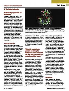
Rodu and Fadi (1998) presented a visual approach to the problem of object grasping and, more generally, to the problem of aligning and end-eŒector with an object. 3.2.5. Robotic ® xture assembly The use of robotic systems is the main method in implementing the automation of modular ® xture assemblies. The robot can con® gure ® xtures into a wide range of workpiece con® gurations without operator assistance. When coupled with ® xture modules designed speci® cally for robot assembly, these systems show promise (Youce-Toumi et al. 1989). In the recon® gurable modular systems developed by Asade and Andre (1985) and Shirinzadeh and Tie (1995), the ® xture modules were set up, adjusted and changed automatically by the assembly robot without human intervention. Lim et al. (1989) used a gantry robot for the loading and unloading of modular ® xtures, an automatic probe-changing coordinate-measurin g machine for inspection. Ngoi et al. (1997) developed an automated ® xture set-up for inspection, the system comprised a workplace with magazines, locators and a baseplate, the SCORBOT-ER VII was used to automate the system. Yu and Goldberg (1998) formalized robotic ® xture loading geometrically as a sensor-base d compliant assembly problem and gave a complete planning algorithm. Giusti et al. (1994) developed a recon® gurable assembly cell for mechanical products. This cell was composed of three base plates, a pneumatic screwing unit, a hydraulic press and other devices for the complete automation of the assembly operations. The handling functions of the cell were performed by a six-axes robot. As shown in ® gure 5, Sela and Gaudry (1997) developed a recon® gurable modular system for the ® xturing of thin-walled, ¯ exible objects subject to a discrete number of point forces.
3.3. FFSs with a single structure The con® gurations of this type of FFSs are unchangeable. However, some adjustable variables are contained. Flexibility can be achieved by changing adjustable variables to accommodate various shapes and sizes of workpieces. Two types are included: the adaptive FFSs, phase-change FFSs. 3.3.1. Adaptive FFSs An adaptive FFS achieves the ¯ exibility through its internal variables. Daniel et al. (1998, 1999) designed a recon® gurable discrete die, which was being developed for
Figure 5.
FFS for thin-walled parts by Sela.
2878
Z. M. Bi and W. J. Zhang
The structure of pin
Figure 6.
A recon® gurable discrete die.
aircraft fuselage parts, made by forming sheet metal or moulding composite materials. As shown in ® gure 6, each pin in the die was a simple hydraulic actuator ® tted with an in-line NC solenoid valve to control its vertical position. Once the pins were set, the entire matrix was clamped into a rigid tool. Brooke (1994) introduced Fanc’s programmable ® xturing system, which could hold diŒerent platforms and multiple models, change quickly, and do it for low cost. Wallack and Canny (1994) designed an adaptive ® xture vice, which consisted of two ® xture table jaws capable of translation in the X axis, As shown in ® gure 7, it was used for 2.5dimensional objects. Du and Lin (1998) developed a three-® ngered automated ¯ exible ® xturing system. Most of grippers used in part assembly belong to this type. As shown in ® gure 8, Kopacek and Kronreif (1994) developed a modular parallel gripper system. Chan and Lin (1996) developed ¯ exible grippers, where only one type of modular element provided locating, supporting and clamping functions. As shown in ® gure 9, each element consisted of four ® ngers with eight degrees of freedom in order to conform to any arbitrary workpiece surfaces. The eight motions of the four ® ngers were controlled by one motor through the use of two transmission and clutch systems. DiŒerent combinations of the multi® ngers could make diŒerent ® xture recon® gurations for the product family. Causey and Quinn (1998) provided a guideline for designing various grippers. Smith (1998) developed a new concept of an intelligent ¯ exible ® xture system.
Figure 7.
A ® xture vice.
Flexible ® xture design and automation
Figure 8.
2879
Gripper with two ® ngers.
Multi-finger module as locators
Multi-Finger module as clam p
Workpiece
Cylinder
Figure 9.
CNC ¯ exible ® xture for assembly.
3.3.2. Phase-change FFSs Flexible ® xturing based on the concept of material phase-change exploits the ability of certain classes of material to change phase. Phase changes may be temperature-induced, electrically induced or a combination of these Temperatureinduced phase-change ® xturing has traditionally been employed in encapsulation for special-purpose precision machining, such as the milling of turban blades as shown in ® gure 10 (Hazen and Wright 1990). Electrically induced phase-change ® xturing employs electro-rheological ¯ uids as the medium undergoing the change of phase, Grippo et al. (1988) developed a prototyp e in ® gure 11, Pseudo phase change ® xtures mimic the function of low melting point alloys. These alloys can be `¯ uidized’ by compressed air, and when the air supply is shut oŒ; the alloys become solid and hold the workpiece (Gandhi and Thompson 1985). Researchers at MIT designed a set of comfortable clamps that use shape memory alloy wires for motive force. As shown in ® gure 12, the clamps consisted of a 4 £ 4 array of ® ngers, normally locked by the squeezing action of heavy-duty belleville springs. Compliant mechanisms are mechanical devices that achieve motion via elastic deformation. by adapting these mechanisms, some special ® xtures can be developed,
2880
Z. M. Bi and W. J. Zhang Workpiece
Hydraulic clamp Compaction plate Container wall Bed Material Air intake Figure 10.
The particulare ¯ uidized bed.
Piston
Array of E-R ‘ plug in’ module
E-R fluid
E-R Valve
Removable module
Figure 11.
Conformable Surface
Fixture made of electropheological ¯ uids.
Lever
Clamping Actuator
Springs Figure 12. MIT Conformable clamp made of shape memory alloy.
Flexible ® xture design and automation
2881
Frecker et al. (1997) discussed topological synthesis of compliant mechanisms using multi-criteria optimization. 3.4. Robotics in ® xture-less assembly (RFA) Robotic ® xture-less assembly refers to the performance of assembly tasks using robots without the ® xtures. RFA is applicable to several industries, including automotive, aircraft, camera and photocopier manufacturing. The elimination of ® xtures is expected to reduce greatly the costs and lengthy lead times associated with retooling in these industries. General Motors of Canada is developing a RFA prototype, it is being used for picking and accurate locating for a large number of complex-shaped sheet metal (and sheet plastic) parts in the assembly processes. Bandyopadhya y et al. (1993) designed a `® xture-free’ machining centre for the machining of block-like components. 4.
Design methodologies Once the whole FFS is bought, selected, or produced, its running e ciency depends largely on the automation degree of design, and veri® cation of the ® xture con® gurations. As mentioned in section 2, three basic activities are involved: (1) description of the requirements and the constraints; (2) modelling in ® xture analysis; and (3) search strategies in ® xture synthesis. A description method has a great eŒect in choosing the appropriate tools for ® xture analysis and synthesis. The geometry expression is the most direct method for describing design requirements. It is often used in the detailed design of a ® xture con® guration both for FFSs and dedicated ® xtures. The alternatives are a GT-based code and feature-based method. To accommodate for computerization, the modular ® xture elements must be encoded (Lin and Huang 1997). Group Technology (GT) codes and feature-based descriptions have appeared in recent years with the increasing usage of expert systems and rule-based systems in ® xture synthesis. However, because the detailed description of design requirements might be di cult, GT is only suitable in the concept design of ® xture con® gurations. 4.1. Methodologies used in ® xture analysis Fixture analysis builds relational models among the design variables, constraints, and evaluation objectives. The optimal formula of the ® xture con® guration design is not completed until all the constraint and objective models are established. 4.1.1. Geometry method The geometry-oriente d approach is a well-accepted approach in which most of the information required can be retrieved from CAD systems. MarkenscoŒ and Papadimitriou (1989) and MarkenscoŒet al. (1990) discussed the geometry of grasping and optimum gripping of a polygon using geometry methods. Trappey et al. (1993) utilized the projective representation of a workpiece to ® nd a feasible ® xture con® guration based on the 3-2-1 locating principle. Asada and Andre (1985) employed analytic tools based on the workpiece geometry and the assembly operation required, and the ® xture con® guration could be changed automatically. Boema and Kals (1988) established a CAD system used for automation of ® xture design and set-ups. Considering the interference between ® xture modules in a recon® gurable ® xture system, Wu and Rong (1998) presented a fundamental study of automated ® xture planning with a focus on geometric analysis. The initial conditions for mod-
2882
Z. M. Bi and W. J. Zhang
ular ® xture assembly were established together with geometric relationships between ® xture components and the workpiece to be analysed. Willy et al. (1995) employed Boolean algebra in justify the possible ® xture con® gurations. Cai et al. (1996, 1997) developed a variational method for robust ® xture con® guration design to minimize workpiece resultant errors due to source errors. Using the proposed variations approach, closed form analytical solutions were derived. Apley and Shi (1998) presented an algorithm to detect and classify multiple ® xture faults based on least squares estimation. Hwang et al. (1999) used kinematics to analyse the grasping of a B-spline surface object by a multi-® ngered robot hand. Hong et al. (1996) applied the spatial point contact constraint theory to develop a mathematical model of ¯ exible ® xturing systems. 4.1.2. Screw theory Screw theory is based on the motion of a rigid body’s displacement in 3D space; the force and the motion of a workpiece can be modelled as `wrenches’ and `twists’ . To build some quality measures for evaluating a grasp, Chou (1989) presented a mathematical theory for automatic con® guration of machining ® xtures for prismatic parts with aid of screw theory, in which twists and wrenches are used to represent the motion and force combinations. Screw theory was used to derive: (1) the minimum number of contacts (locations and clamps); (2) the permissible motions due to a contact set; (3) the reaction forces at special contacts; and (4) the clamping forces required to balance cutting forces (Fuh and Nee 1994). 4.1.3. Finite Element Method (FEM) Owing to its good capability of deriving the corresponding compressive force and displacement, the FEM approach has been used in many de¯ ection-related researches (Hou and Trappy 1997). Lee and Cuthowsky (1990) were the ® rst to employ this method in Automated Fixture Design (AFD). De Meter (1998) proposed the Fast Support Layout Optimization (FSLO) model, it utilized a FEM model to characterize workpiece stiŒness. Solution of the FSLO model improved an existing support layout by systematically altering the boundary conditions. 4.1.4. Rule-based or feature-based analysis In a feature-based model, a typical approach is to represent a part with a single set of features. In machining processes, diŒerent ® xturing parameters are required when diŒerent sets of features are used for machining. Tseng (1998) developed a feature-based ® xturing analysis method to determine a good set of features that was more suitable from the ® xturing point of view. Dong et al. (1991) investigated the use of features for ® xture design, concentrating on the selection of locating elements and the identi® cation of locating surfaces for workpiece positioning. The approaches of machining feature-based design and the precedence matrix algorithm were combined to automate the process-planning and ® xture design (Ozturk et al. 1996). By merging knowledge of manufacturing methods and machine tool information with a special-purpose computer language, Darvishi and Gill (1988) suggested developing, primarily for list processing and symbolic manipulation, ground rules for a ® xture design approach. A ® xture process planning system was implemented using a knowledge-based approach (Liou and Suen 1992). Perremans (1996) described modular elements by means of form
Flexible ® xture design and automation
2883
features; this permitted the description of an arbitrary modular ® xturing system and the use of the same logic to determine the assembly of modular elements. 4.1.5. Mechanical analysis methods As well as the methodologies mentioned above, the mechanical analysis method is very popular for modelling workpiece-® xture force interactions and deformations of the workpiece. King et al. (1997) presented an analytical approach based on kinematics, force and a minimization of potential energy method. Potential energy was regarded as a measure of excitability of a given physical state, the physical state considered was the ® xturing con® guration of locators and clamps, and an optimal algorithm was built to ® nd a con® guration with the minimum potential for perturbation. Meyer and Liou (1997) developed a comprehensive methodology for handling the dynamic external force in a workpiece-® xturing system. Considering the accurate and e cient modelling of compliant ® xtures and grasps, Lin (1998) derived a stiŒness matrix formula using the overlap compliance representation for quasirigid bodies. It could incorporate a realistic nonlinear contact model, and could be directly computed from CAD data on basic geometric and material properties of the bodies. This formula was well-suited to automated planning algorithms. Mittall and Cohen (1991) presented a dynamic modelling of the ® xture-workpiece system. Most of force analysis approaches treated either the workpiece or the ® xture as a deformable elastic body; however, both of them were considered as deformable elastic bodies in the mechanical analysis presented by Gui et al. (1996); a generalized method to minimize the location deviation was proposed by using optimally determined clamping forces. Nguyen (1984) discussed constructing stable grasps using mechanical modelling. Yeh and Liou (1999) developed the modelling of the response frequency of a modular ® xturing system with multiple components in contact, and showed it was possible to monitor the contact conditions based on a ® xture system’s dynamic response frequency. Wu et al. (1997) considered surface contact modelling for a ® xture± workpiece system. Shreyes and Melkote (1997) applied the mechanical method to improving workpiece location accuracy through ® xture layout optimization.
4.2. Methodologies for ® xture synthesis Two main considerations in ® xture synthesis are to simplify the synthesis process and to reduce calculations. In addition, search strategies in the feasible space of ® xture con® gurations are important. 4.2.1. Analytical methods Analytical synthesis can only handle a small number of design variables. Two possible situations might use analytical synthesis: (1) the determination of a ® xture con® guration for the SFFSs with a few variables; (2) the determination of a few internal parameters for selected modular elements for MFFSs when the whole complex design has been decomposed. Brost et al. (1996) presented an implemented algorithm that accepted a polygonal description of the part silhouette, and e ciently constructed the set of all feasible ® xture designs that kinematically constrain the part in the plane. Rong and Bai (1997) designed a Modular Fixture Element Assembly Relationship Graph (MFEARG) to represent combination relationships between ® xture elements. Based on MFEARG, synthesis algorithms were developed to
2884
Z. M. Bi and W. J. Zhang
search all suitable ® xturing unit candidates and mount them into appropriate positions on a base-plate with interference checking. 4.2.2. Rule-based reasoning The use of acknowledge-base d computer design scheme will help to introduce the essential philosophy to ensure that the optimum design is achieved. Nee (1987) applied AI in jig and ® xture design. Nnaji et al. (1988) and Nnaji and Alladin (1990) developed a framework for a rule-based expert ® xturing system for face milling a planar surface on a CAD system using ¯ exible ® xtures. Roy et al. (1997) addressed several implementation issues of a prototype AFM system. Such AFD systems proposed a preliminary ® xturing con® guration by synthesizing the ® xture design issues and reasoning about the necessary knowledge bases. Trappey and Liu (1992) employed heuristic search techniques on the projected envelope of the workpiece to determine the locating and clamping points. King and Lazaro (1994) presented a ® xture synthesis algorithm a hybrid (heuristic-cum-mathematical ) model to arrive at design decisions. Lin and Huang (1997) developed diŒerent heuristic algorithms for ® xture element selection corresponding to diŒerent functional requirements. 4.2.3. Genetic algorithm Fixture Design is generally regarded as a complex multi-modal and discrete problem. While other methods have di culties dealing with it, the trials on GAs have provided a viable alternative. Wu and Chan (1996) applied genetic algorithms to the ® xture con® guration optimization: based on the information provided by the veri® cation system, a genetic algorithm approach carries out the evaluation process to determine the most statically stable ® xture con® guration among a large number of candidates. 4.2.4. Case-based method In the CBR concept previous experience is stored as episodes in a case library. Each episode, termed a case, records at least two kinds of information: problem description and solution. When a CBR system faces a new problem, the most similar previous case is retrieved and modi® ed to satisfy the new situation. Each case and the input problem are indexed according to the index system. The similarity of each case can then be evaluated by comparing the index of each case with the index of the input problem. Sun and Chen (1995) developed a seven-digit code to represent and classify the modular ® xtures. Using this index system and case-based method, the designer can ® nd a rough sketch of this ® xture design. 4.2.5. Neural network algorithms After network training, the ® xture mode of the workpiece can be inferred, and selection of the ® xture elements can be completed. Ong and Nee (1996, 1998) applied fuzzy theory to evaluate part ® xturability. Lin integrated the GT description of modular ® xtures, neural networks, and the heuristic algorithm for ® xture synthesis in his automatic ® xture design system. Genetic algorithms and neural networks can be combined in a ® xture design system (Lin 1998); Kumar et al. (1992) applied this integration methodology in conceptual design of ® xtures.
2885
Flexible ® xture design and automation
4.2.6. Blackboard-base d design Blackboard-based design systems are used in various other engineering applications in which concurrent or cooperative problem solving processes are achieved. Fixture design involves interdisciplinary knowledge, with the help of blackboard architecture. The developed ® xture design system could perform lower level reasoning and allow the analysis to be integrated with the design process, so that reliability assessment can be accomplished when it could best aŒect the design (Roy and Liao 1998). 4.3. Summary of the methodologies in ® xture design Fixture con® guration design can be separated into three phases: description of design requirements, the ® xture analysis, and ® xture synthesis. Fixture analysis involves the relational models among design variables, kinematic and dynamic constrictions, and performance evaluation; while ® xture synthesis involves ® nding an optimal solution for a given workpiece and its machining. Many methodologies have developed for designing a ® xture con® guration. However, a suitable methodology is very important for a given design requirement and design level to improve e ciency, and the harmony of the methodologies should be maintained. A brief summary on the methodologies used in ® xture design is given in Table 3.
5.
Computer-aided ® xture design and set-up system A review is presented on computer-aided ® xturing design and set-up systems.
5.1. Architecture of computer-aided ® xture design and set-up system Software architecture describes the system components and their relationships. Bugtai and Young (1997) discussed the information model in an integrated ® xture design support system. Nederbragt (1997) proposed a theoretical framework for the design of a robotic ® xture. Fuh and Nee (1995) presented the architecture and details
Description of design requirement
Geometry method Featurebased GT codes
Fixture analysis Fixture synthesis
Analytical methods Rule-based Genetic agorithm case-based Neural networks
p
p
£ £
£ £
Geometry modelling p
Screw theory p
£ £
£ £
£ £
£ £
p
p
p
p
p p
p
Finite element method
Rule-based knowledge
£
£
Mechanics methods p
£
p p
£ £
p p p p
£ means two methodologies are not compatible. p means two methodologies are compatible.
Table 3.
Summary on the methodologies in ® xutre design.
£
£ £ £ £
2886 Developers and resource Pham and Lazaro (1990) Nnaji and Alladin (1990) Young and Bell (1991) de Sam Lajaro and King (1992) Lim et al. (1992) Trappy and Liu (1992) Wolter and Trinkle (1994) King and de Sa Lazaro (1994) Brost and Goldberg (1994) Mason (1995) Willy et al. (1995) Sun and Chen (1995) Perremans (1996) Cecil et al. (1996) Shirnzadeh (1996)
Wu and Chan (1996) Rong (1996) Rong and Bai (1997)
Z. M. Bi and W. J. Zhang
Application
Methodology
Jigs and ® xture
Expert CAD system ® nite element method Rule-based expert system
Face milling planar part, ¯ exible ® xtures Two and half dimensional prismatic arts Machining ® xture part ® xturing in high-precision industry, Workholding veri® cation Selection of ® xture point, frictionless assemblies Tolerance consideration, general ® xture Polygonal parts, modular ® xture General ® xture Modular ® xture Modular ® xture Prismatic parts, modular ® xture Prismatic parts, general ® xture Interference detection, recon® gurable modular ® xture system Optimal ® xture con® guration Machining accuracy analysis design veri® cation
Geometric query, product model analysis Tolerance and sequential operations analysis 3D modular ® xture design expert system Geometry analysis Geometry method Knowledge-based systems Geometric analysis Finite element method Geometry and mechanic analysis Cased-based reasoning, index system Feature-based description, expert system Integration methodology CAD-based heirarchical approach
Jones et al. (1997)
Automated assembly and ® xture planning
Generic algorithm Datum-machining surface relationship graph, matrixbased reasoning Archidedes’ s approach holdfast software
Ho and Ranky (1997)
Flexible assembly system, recon® gurable conveyors
Object-oriented modelling, heuristic searching
Roy et al. (1997)
Prismatic parts, modular ® xture
Geometry reasoning, object-oriented
Chou (1997) Wu and Rong (1998)
Complex part, general ® xture Dedicated ® xture
Lin and Huang (1997) Jeng and Gill (1997)
3D workpieces, modular ® xture Prismatic parts
Fixturing feature analysis, spatial inference analysis Fixture structure analysis, geometry± element generator GT, neural networks, pattern classi® cation CAD-based approach Table 4 (continued)
Flexible ® xture design and automation Developers and resource
2887
Application
Methodology
Brost and Peters (1998) Ma et al. (1998)
Prismatic machining parts, general ® xture 3D workpiece, modular ® xture and assembly pallets Modula ® xture
Roy and Liao (1998)
General ® xture
Brown and Brost (1999) Kumar et al. (1999)
3D prismatic parts,
Feature-based analysis, CAD/CAM integration Project geometry, mechanic analysis Geometry modelling, Integration with CAD, system Cooperative design, blackboard framework 3D geometric analysis
Shreyes and Melkote (1999)
Location accuracy, ® xture layout optimization
Tseng (1998)
Conceptual design of ® xture
Table 4.
Genetic algorithm, neural networks Mechanic analysis
Summary of recent developed CAFD systems.
of the development of an interactive ® xture design and assembly (IFDA) environment. Chou (1997) presented a three-stage system architecture from a concurrent manufacturing planning point of view. Jeng and Gill (1997) thought that arti® cial intelligence techniques should be used in conjunction with 3D solid CAD and database systems at the commercial level for modular ® xture design, pricing and inventory control. Greater emphasis should be put on the integration of the intelligent ® xture design system with the robotics ® xture assembly, knowledge-based process planning system, and intelligent production scheduling system (Chou 1997). 5.2. Computer-aided ® xture design (CAFD) Computer-aided ® xture design is mainly relevant to MFFSs and dedicated ® xtures. Many CAFD prototype systems have been developed; some CAFD systems, together with applications and using methods, are shown in table 4. 5.3. Computer-aided ® xture setup (CAFS) for MFFSs One of the di culties in the application of MFFSs is to plan and execute the setup of modular elements. The assembly location and sequence should be determined for all modular elements in a CAFS system. Little attention has been paid to this issue. Table 5 provides a summary of these works. 6.
Some prospective research trends Recent achievements in the development of ¯ exible ® xture systems, design methodologies, together with computer-aided design and set-up systems have been examined in this paper. Adaptation of FFSs can greatly reduce manufacturing costs in low-to-medium volume products, and the design and set-up automation of FFSs can reduce the lead-time of the product; however, the current design and automation theories and technologies are not mature. The researches on these ® elds are promising and challenging. It is our observation that three research aspects are most promising.
2888
Z. M. Bi and W. J. Zhang
Developers and Resource
Application
Methodology
Asada and Andre (1985)
Sheet metal ® xturing
Accessibility and detachability analysis
Lam and Lim (1989)
Modular ® xture assembly
Robotics oç ine programming
Youce-Toumi and Bell (1989)
Modular ® xture assembly
Integration CAD systems, kinematic analysis
Dai and Nee (1997)
Assembly sequence
Rule-based reasoning
Khan and Cegiarek (1998)
Assembly for sheet metal part ® xture
Hierarchical group description, fault diagnosis
Yu and Goldberg (1998)
Module ® xture assembly
Sense-based compliant assembly, geometrically reasoning
Table 5.
Summary of computer-aided ® xture setup systems for MFFSs.
6.1. Development of an autonomou s ¯ exible ® xture system In today’s FFSs, especially for MFFSs, ® xture design, veri® cation, and assembly largely depend on human activities. This situation has resulted in the low e ciency, unstable accuracy, long set-up time, and high cost of FFSs. Development and application of autonomous ¯ exible ® xture systems can address this issue. The state of the art in this ® eld shows the possibility of developing a autonomous ¯ exible ® xture system. `Autonomous’ means to implement the automatic running of an FFS with the aid of ¯ exible elements and automatic servo control, arti® cial intelligence and sensing. An AFFS should possess the following characteristics: (1) have a large degree of freedom to accommodate the ® xturing feature varieties of the workpiece family; (2) determine optimal ® xture con® guration based on design requirements automatically; (3) build the ® xture con® guration automatically by adjusting internal variables or assembling modules; (4) load the workpiece in the ® xture± workpiece system automatically; (5) monitor ® xturing processes and adjust the con® guration dynamically to achieve the best manufacturing performance; (6) unload the workpiece and reset the ® xturing system automatically.
6.2. Computer-aided ® xture design for manufacturing Many researchers have realized the importance of integration CAFD systems with other CAD software systems in a manufacturing system. However, their eŒorts showed that they mainly concentrated on CAFD systems, and the integration was limited to obtaining the ® xturing requirements from other CAD systems and sending the result of the CAFD to CAPP systems directly; this is a single-direction connection. Most research works have neglected the eŒect of ® xture design on product design and process planning, and the redesign of ® xtures has never been seriously considered. Future research on CAFD will put the emphasis on cooperation with the other design systems, the connection should be bi-directional, and the CAFD process
Flexible ® xture design and automation
2889
information should also be fed back to the other system as early as possible. In considering the integration of the CAFD system with the other CAD manufacturing systems, combination with advanced computer technologies, such as a WWW browser, collaborative design system, integration architecture of various platforms, becomes urgent. 6.3. Applied research Practical issues also appear when ¯ exible ® xture systems are put into use. Not all research has taken the issues seriously. However, the solutions for these issues are vital to extend the application of FFSs. 6.3.1. Select or design a ¯ exible ® xture system for workpiece families Any FFS has favourable ® xturing features in its application. An engineer has a responsibility to select or design the most suitable FFS for the manufacturing part family. Therefore, it becomes a meaningful issue to select, evaluate and design a FFS for a part family optimally. This issue is more di cult than the design of a ® xture con® guration, because the ® xturing objects have uncertain requirements. To address this issue, some qualitative considerations should be included in the evaluation models, such as cost, e ciency, suitability and lead time. 6.3.2. From dedicated ® xtures to FFSs Liu (1994) proposed a systematic design method that helped companies change their dedicated ® xturing systems gradually into modular ® xturing systems. This research is very practical. Further research should be carried out, such as how to design dedicated ® xture elements for evolving FFSs, how to improve the possibilities of varieties of ® xture con® gurations from the systems, how to manage the dedicated and ¯ exible ® xture hybrid systems, etc. The solutions to these issues can bring great economic e ciency to small-scale machining enterprises. 6.3.3. Multi-® xtures and multi-® xturing tasks schedule In a real machining workshop, there may be various FFSs, dedicated ® xtures and many workpieces. Dynamic scheduling methodology is needed to distribute the limited ® xture resources for ® xturing workpieces. Some researchers have revealed tooling management issues in manufacturing industry (Arun and Suresh 1996, Ebrahim and Liu 1995, Elon and Burdick 1998, Perera and Sharfaghi 1995). However, they are mainly concerned with the scheduling issues of general machining tools. The schedules of FFSs and their elements pose many special characteristics. References Apley, D. W. and Shi, J., 1998, Diagnosis of multiple ® xture faults in panel assembly. Transaction of the ASME, Journal of Manufacturing Science and Engineering, 120, 793± 801. Arun, S. S. and Suresh, K. K., 1996, Analysis of tool sharing in an FMS: a simulation study. Computers in Industry Engineering, 30(1), 137± 145. Asada, H. and Andre, B. B., 1985, Kinematic analysis of workpart ® xturing for ¯ exible assembly with automatically recon® gurable ® xtures. IEEE Journal of Robotics and Automation, 1(2), 86± 93. Bandyopadhyay, B. P., Hoshi, T., Latief, M. A. and Hanada, T., 1993, Development of a ® xture-free machining center for machining block-like components. Journal of Materials Processing Technology, 39(3± 4), 405± 413.
2890
Z. M. Bi and W. J. Zhang
Barsky, M. F., Lindner, D. K. and Claus, R. O., 1989, Robot gripper control system using PVDF piezoelectric sensors. IEEE Transactions of Ultrasonics, Ferroelectrics, and Frequency Control, 30(1), 129± 134. Benhabib, B., Chan, K. C. and Dai, M. Q., 1991, A modular programmable ® xturing system. Transaction of the ASME, Journal of Engineering for Industry, 113, 93± 100. Boema, J. R. and Kals, H. J., 1988, FIXES: a system for automatic selection of set-ups and design of ® xtures. CIRP Annals, 37(1), 443± 446. Brooke, L., 1994, Flex factor. Chilton’s Automotive Industries, 174(11), 50± 52. Brook, N., Shoham, M. and Dayan, J., 1998, Multi-® ngered hands. IEEE Transactions on Robotics and Automation, 14(1), 185± 192. Brost, R. C. and Goldberg, K. Y., 1994, A complete algorithm for synthesizing modular ® xtures for ploygonal parts. IEEE International on Robotics and Automation, 535± 542. Brost, R. C. and Goldberg, K. Y., 1996, A complete algorithm for designing planar ® xtures using modular components. IEEE Transaction on Robotics and Automation, 12(1), 31± 46. Brost, R. C. and Peters, R. R., 1998, Automatic design of 3-D ® xtures and assembly pallets. The International Journal of Robotics Research, 17(2), 1243± 1281. Brown, R. G. and Brost, R. C., 1999, A 3-D modular gripper design tool. IEEE Transactions on Robotics and Automation, 15(1), 174± 186. Bugtai, N. and Young, R. I. M., 1997, Information models in an integrated ® xture design support tool. Journal of Materials Processing Technology, 76(1± 3), 29± 35. Cai, W., Hu, S. J. and Yuan, J. X., 1996, Deformable sheet metal ® xturing: principles, algorithms and simulations. Transaction of the ASME, Journal of Manufacturing Science and Engineering, 118, 318± 324. Cai, W., Hu, S. J. and Yuan, J. X., 1997, A variational method of robust ® xture con® guration design for 3-D workpieces. Transaction of the ASME, Journal of Manufacturing Science and Engineering, 119, 593± 602. Causey, G. C. and Quinn, R. D., 1998, Gripper design guidelines for modular manufacturing. Proc. Of 1998 IEEE International Conference on Robotics and Automation, Part 2 (of 4) 16± 20 May, Leuven, Belgium, pp. 1453± 1458. Cecil, J., Mayer, R. and Hari, U., 1996, An integrated methodology for ® xture design. Journal of Intelligent Manufacturing, 7(2), 95± 106. Ceglarek, D. and Shi, J., 1996, Fixture failure diagnosis for autobody assembly using pattern recognition. Transactions of the ASME, Journal of Engineering for Industry, 118, 55± 66. Chan, K. C. and Lin, C. S., 1996, Development of a computer numerical control (CNC) modular ® xture-machine design of a standard multi® nger module. International Journal of Advanced Manufacturing Technology, 11(1), 18± 26. Chang, C.-H., 1992, Computer-assisted ® xture planning for machining processes. Manufacturing Review, 5(1), 15± 28. Choudhuri, S. A. and De Meter, E. C., 1999, Tolerance analysis of machining ® xture locators. Transactions of the ASME, Journal of Manufacturing Science and Engineering, 121, 273± 224. Chou, Y.-C., 1989, A mathematical approach to automatic con® guration of machining ® xtures: analysis and synthesis. Transactions of the ASME, Journal of Engineering for Industry, 111, 299± 306. Chou, Y.-C., 1997, Automated planning and design of ® xture for complex parts. International Journal of Computer Applications in Technology, 10(3± 4), 183± 197. Dai, J. R. and Nee, A. Y. C., 1997, An approach to automating modular ® xture design and assembly. Proceedings of the Institution Mechanical Engineers, Part B, 211(B7), 509± 521. Darvishi, A. R. and Gill, K. F., 1988, Knowledge representation database for the development of a ® xture design expert system. Proceedings of the Institution of Mechanical Engineers, Part B, 202, 37± 49. De Meter, E. C., 1998, Fast support layout optimization. International Journal of Machine Tools & Manufacture, 38(10), 1221± 1239. De Sam Lazaro, A. and King, D. A., 1992. Automated design of machining ® xtures: tolerance and sequential operations. Intelligent Systems Engineering, 1(2), 172± 184.
Flexible ® xture design and automation
2891
Dong, X., Devries, W. R. and Wozny, 1991, Feature-based reasoning in ® xture design. Annals of the CIRP, 40(1), 111± 114. Du, H. and Lin, G. C. I., 1998, Development of an automated ¯ exible ® xture for planar objects. Robotics and Computer-Integrated Manufacturing, 14(3), 173± 183. Ebrahim, S. and Liu, C.-L., 1995, Tool management in ¯ exible manufacturing systems. Integrated Manufacturing Systems, 6(4), 26± 35. Elon, R. and Burdick, J. W., 1998, Mobility of bodies in contactÐ Part I: a 2nd-order mobility index for multiple-® nger grasps. IEEE Transaction on Robotics and Automation, 14(5), 696± 709. Frecker, M. I., Ananthasuresh, G. K., Nishiwaki, S. S., Kikuchi, N. and Kota, S., 1997, Topological synthesis of compliant mechanisms using multi-criteria optimization. Transactions of the ASME, Journal of Mechanical Design, 119, 238± 244. Fuh, J. Y. H. and Nee, A. Y. C., 1995, IFDA: an interactive ® xture design and assembly environment. International Journal of Computer Applications in Technology, 8(1/2), 30± 40. Fuh, J. H. and Nee, A. Y. C., 1994, Veri® cation and optimization of workholding schemes for ® xture design. Journal Design & Manufacturing, 4(4), 307± 318. Gandhi, M. V. and Thompson, B. S., 1985, Phase-change ® xturing for ¯ exible manufacturing systems. Journal of Manufacturing System, 4(1), 29± 39. Giusti, F., Santochi, M., Dini, G. and Arioti, A., 1994, Recon® gurable assembly cell for mechanical products. International Institute for Production Engineering Research, 43(1), 1± 4. Grippo, P. M., Thompson, B. S. and Gandhi, M. V., 1988. A review of ¯ exible ® xture systems for computer-integrated manufacturing. International Journal of ComputerIntegrated Manufacturing, 1(2), 124± 135. Gui, X., Fuh, J. Y. H. and Nee, A. Y. C., 1996, Modeling of frictional elastic ® xture-workpiece for improving location accuracy. IEE Transactions (Institute of Industrial Engineers), 28(10), 821± 827. Hargrove, S. K., 1995, A systems approach to ® xture planning and design. International Journal of Advanced Manufacturing Technology, 10(3), 169± 182. Hargrove, S. K. and Kusiak, A., 1994. Computer± aided ® xture design: A Review. International Journal Product Research, 32(4), 733± 753. Hazen, F. B. and Wright, P. K., 1990, Workholding automation: innovations in analysis, design and planning. Manufacturing Review, 3(4), 224± 236. He, D. W. and Kusiak, A., 1997, Design of assembly systems for modular products. IEEE Trans. On Robotics and Automation, 13(5), 646± 655. He, D. W. and Kusiak, A., 1996, Performance analysis of modular product. International Journal of Product Research, 34(1), 253± 272. Ho, J. K. L. and Ranky, P. G., 1997, Object oriented modeling and design of recon® gurable conveyors in ¯ exible assembly systems. International Journal of Computer Integrated Manufacturing, 10(5), 360± 379. Hockenberger, M. J., 1995, The eŒect of machining ® xture design parameters on workpiece displacement. Manufacturing Review, 8(1), 22± 32. Hong, M., Payandeh, S. and Gruver, W. A., 1996, Modeling and analysis of ¯ exible ® xture systems for agile manufacturing. Proceedings of the IEEE International on Systems, Man and Cybernetics, 2, 1231± 1236. Hou, J. L. and Trappy, A. J. C., 1997, A methodology for applying V-blocks and clamps to non-prismatic workpart ® xtures. International Journal Computer Applications in Technology, 10(3± 4), 152± 169. Hwang, C.-S., Masaharu, T. and Ken, S., 1999, Kinematics of grasping and manipulation of a B-spline surface object by a multi-® ngered robot hand. Journal of Robotics Systems, 16(8), 445± 460. Jeng, Y. C. and Gill, K. F., 1997, A CAD-based approach to the design of ® xture for prismatic parts. Proceedings of the Institution of Mechanical Engineers, Part B, 211(B7), 523± 538. Jones, R. E., Calton, T. L. and Peters, R. R., 1997, Automated assembly and ® xture planning at Sandia national laboratories. Assembly Automation, 17(3), 201± 205.
2892
Z. M. Bi and W. J. Zhang
Kurz, K., Craig, K., Wolf, B. and Stolfi, F., 1994, Developing a ¯ exible automate ® xturing device. Mechanical Engineering, 59± 63. Khan, A. and Ceglarek, D., 1998, Sensor location optimization for Fault miagnosis in multi-® xture assembly systems. Transaction of the ASME, Journal of Manufacturing Science and Engineering, 120, 781± 792. King, D. A. and de Sam Lazaro, A., 1994, Process and tolerance considerations in the automated design of ® xtures. Transactions of the ASME, Journal of Mechanical Design, 116, 480± 486. King, L. S.-B., Ling, F. F. and King, A. G., 1997, Optimization of potential energy for positioning ® xturing locators. International Journal of Computer Applications In Technology, 10(3± 4), 117± 132. Kopacek, P. and Kronreif, G., 1994, Modular parallel gripper system. International Symposium on Industrial Robotics, 25± 27, April, Hannover, Germany, pp. 89± 94. Kumar, A. S., Nee, A. Y. C. and Prombanpong, S., 1992, Expert ® xture-design system for an automated manufacturing environment. Journal of Computer-Aided Design, 24(6), 316± 326. Kumar, A. S., Subranmaniam, V. and Seow, K. C., 1999, Conceptual design of ® xtures using genetic algorithms. International Journal of Advanced Manufacturing Technology, 15(2), 79± 84. Kusiak, A. and Larson, N., 1995, Decomposition and representation methods in mechanical design. Transactions of the ASME, Special 50th Anniversary Design Issue, 117, 17± 24. Lam, S. L. and Lim, B. S., 1989, Integrated robotics oŒ-line programming system for modular ® xture assembly. Journal of Mechanical working technology, 20, 261± 271. Lee, S. H. and Cutkosky, M. K., 1990, Fixture planning with friction. Transactions of the ASME, Journal of Engineering for Industry, 13, 320± 327. Lim, B. S., Imao, T., Yoshida, H., Goto, K., Koh, S. L., Lim, D., Chin, L. and Gan, S. C., 1992, Integrated modular ® xture design, pricing and inventory control expert system. Journal of Production Research, 30(9), 201± 2044. Lim, R. S., Lim Beng, C. and Ho, N., 1989, Development and implementation of intelligent ¯ exible manufacturing system. Journal of Mechanical Working Technology, 20, 389± 402. Lin, Q., 1998, Mechanics and planning of workpiece ® xturing and robotics grasping (stiŒness, de¯ ection). PhD thesis, California Institute of Technology. Lin, Z.-C. and Huang, J.-C., 1997, The application of neural networks in ® xture planning by pattern classi® cation. Journal of Intelligent Manufacturing, 8(4), 307± 322. Liou, F. W. and Suen, D., 1992, The development of a feature-based ® xture process planning system for ¯ exible assembly. Journal of Manufacturing Systems, 11(2), 102± 113. Liu, C.-L., 1994, Systematic conceptual design of modular ® xtures. International Journal of Advanced Manufacturing Technology, 9(4), 217± 224. Liu, J. and Strong, D. R., 1993, Survey of ® xture design automation. Transactions of the CSME, 17(4A), 585± 611. Lu, S.-S., Chu, J.-J. and Jang, H.-C., 1997, Development of a novel coordinate transposing ® xture system. International Journal of Advanced Manufacturing Technology, 13(5), 350± 358. Ma, W., Lei, Z. and Rong, Y., 1998, FIX-DES: A computer-aided modular ® xture con® guration design system. International Journal of Advanced Manufacturing Technology, 14(1), 21± 32. Markenscoff, X. and Papadimitriou, C. H., 1989, Optimum grip of a polygon. International Journal of Robotics Research, 8(2), 17± 29. Markenscoff, X., Ni, L. and Papadimitriou, C. H., 1990, The geometry of grasping. International Journal of Robotics Research, 9(1), 61± 74. Mason, F., 1995, Computer-aided ® xture design. Manufacturing Engineering, 114(6), 41± 45. Meyer, R. T. and Liou, F. W., 1997, Fixture analysis under dynamic machining. International Journal of Production Research, 35(5), 1471± 1489. Mittal, R. O. and Cohen, P., 1991, Dynamic modelling of the ® xture-workpiece system. Robotics & Computer-Integrated Manufacturing, 8(4), 201± 217. Nederbragt, W. W., 1997, Design of tactile ® xtures for robotics and manufacturing. Transactions of the ASME, Journal of Mechanical Design, 119, 204± 211.
Flexible ® xture design and automation
2893
Nee, A. Y. C., 1987, Applying AI in jigs and ® xtures design. Robotics and ComputerIntegrated Manufacturing, 3(2), 195± 200. Newcomb, P. J. B., Bras, B. and Rosen, D. W., 1998, Implications of modularity on product design for the life cycle. Transactions of the ASME, Journal of Mechanical Design, 120, 483± 490. Nnaji, B. O. and Alladin, S., 1990, E-CAFFS: an expert computer-aided ¯ exible ® xturing system. Computers and Industrial Engineering, 18(3), 297± 311. Nnaji, B. O., Alladin, S. and Lyu, P., 1988, A framework for a rule-based expert ® xturing system for face milling plannar surfaces on A CAD system using ¯ exible ® xtures. Journal of Manufacturing Systems, 7(3), 193± 207. Ngoi, B. K. A., Tay, M. L. and Wong, C. S., 1997, Development of an automated ® xture setup system for inspection. International Journal of Advanced Manufacturing Technology, 13(5), 342± 349. Nguyen, V. D., 1989, Constructing stable grasps. The International Journal of Robotics Research, 8(1), 26± 37. Ong, S. K. and Nee, A. Y. C., 1996, An intelligent fuzzy set-up planner for manufacturability and ® xturability evaluation. International Journal of Production Research, 34(3), 665± 686. Ong, S. K. and Nee, A. Y. C., 1998, A systematic approach for analyzing the ® xturability of parts for machining. Journal of Manufacturing Science and Engineering, 120, 401± 408. Ozturk, F., Kaya, N., Alankus, O. B. and Seving, S., 1996, Machining features and algorithms for set-up planning and ® xture design. Computer Integrated Manufacturing Systems, 9(4), 207± 216. Perera, T. and Shafaghi, M., 1995, Analysis of tooling problems in discrete manufacturing industry. International Journal of Operations & Production Management, 15(12), 75± 85. Perremans, P., 1996, Feature-based description of modular ® xturing elements: the key to an expert system for the automatic design of the physical ® xture. Advanced in Engineering Software, 25(1), 19± 27. Pham, D. T. and Lazaro, A., 1990, Auto® x± an expert CAD system for jigs and ® xtures. International Journal of Machine Tools Manufacturing, 30(3), 403± 411. Radu, H. and Fadi, D., 1998, Visually guided object grasping, IEEE Transactions on Robotics and Automation, 14(4), 525± 531. Rogers, G. G. and Bottaci, L., 1997, Modular production systems: a new manufacturing paradigm. Journal Intelligent Manufacturing, 8(3), 147± 156. Rong, Y., 1996, Machining accuracy analysis for computer-aided ® xture design veri® cation. Transactions of the ASME, Journal of Manufacturing Science and Engineering, 118, 289± 300. Rong, Y. and Bai, Y., 1997, Automated generation of ® xture con® guration design. Journal of Manufacturing Science and Engineering, Transactions of the ASME, 119(2), 208± 219. Roy, U. and Liao, J., 1998, Application of a blackboard framework to a cooperative ® xture design system. Computers in Industry, 37(1), 67± 81. Roy, U., Liao, J., Sun, P.-L. and Fields, M. C., 1997, Fixture design synthesis for a ¯ exible manufacturing system. Integrated Computer-aided Engineering, 4(2), 101± 113. Sela, M. N. and Gaudry, O., 1997, Recon® gurable modular ® xture system for thin-walled ¯ exible objects. International Journal of Advanced Manufacturing Technology, 13(9), 611± 617. Sheyes, B. L. and Melkote, N., 1999, Improved workpiece location accuracy through ® xture layout optimization. International Journal of Machine Tools & Manufacture, 39(6), 871± 883. Shimoga, K. B., 1996, Robot grasp synthesis algorithms: a survey. The International Journal of Robotics Research, 15(3), 230± 266. Shirinzadeh, B. and Tie, Y., 1995, Experimental investigation of the performance of a recon® gurable ® xture system. International Journal of Advanced Manufacturing Technology, 10(5), 330± 341. Shirinzadeh, B., 1995, Flexible and automated workholding systems. Industrial Robot, 22(2), 29± 34.
2894
Flexible ® xture design and automation
Shirinzadeh, B., 1996, A CAD-based hierarchical approach to interference detection among ® xture modules in a recon® gurable ® xturing system. Robotics and Computer-Integrated Manufacturing, 12(1), 41± 53. Smith, P. L., 1998, A ¯ exible ® xturing future. American Machinist, 142(4), 62± 73. Sun, S. H. and Chen, J. L., 1995, A modular ® xture design system based on case-based reasoning. International Journal of Advanced Manufacturing Technology, 10(6), 389± 395. Tao, Z. J. and Kumar, A. S., 1997, Modelling and experimental investigation of a sensorintegrated workpiece-® xture system. International Journal Computer Applications in Technology, 10(3± 4), 236± 250. Taylor, M., Blacke, A. and Cox, A., 1994, Visually guided grasping in 3D. IEEE Int. Conf. on Robotics and Automation, San Diego, CA, 8± 13 May, pp. 761± 766. Trappey, A. C. and Liu, C. K., 1990, A literature survey of ® xture-design automation. International Journal of Advanced Manufacturing Technology, 5(3), 240± 255. Trappey, A. C. and Liu, C. K., 1992, An automatic workholding veri® cation system. Robotics and Computer-Integrated Manufacturing, 9(4± 5), 321± 326. Trappey, A. C. and Matrubhutam, S., 1993, Fixture con® guration using projective geometry. Journal of Manufacturing Systems, 12(6), 486± 495. Tseng, Y. J., 1998, Feature-based ® xturing analysis for machining parts represented with multiple sets of features. International Journal of Production Research, 36(10), 2743± 2770. Wallack, A. S. and Canny, J. F., 1994, Planning for modular and hybrid ® xtures. Proceedings of the 1994 IEEE International Conference on Robotics and Automation, San Diego, CA, 8± 13 May, pp. 520± 527. Willy, A., Sadler, J. P. and Schraft, K. D., 1995, Automated ® xture design. International Journal of Advanced Manufacturing Technology, 10(1), 27± 35. Walczyk, D. F., Lakshimikanthan, J. and Kirk, D. R., 1998, Development of a recon® gurable tool for forming aircraft body panels. Journal of Manufacturing Systems, 17(4), 287± 296. Walczyk, D. F., Lakshimikanthan, J. and Kirk, D. R., 1999, A comparison of rapid fabrication methods for sheet metal forming dies. Transaction of the ASME, Journal of Mechanical Design, 121, 214± 223. Wolter, J. D. and Trinkle, J. C., 1994, Automatic selection of ® xture points for frictionless assemblies. IEEE International Conference on Robotics and Automation, San Diego, CA, 8± 13 May, pp. 528± 534. Wu, N. H. and Chan, K. C., 1996, A genetic algorithm based approach to optimal ® xture con® guration. Computers & Industrial Engineering, 31(3/4), 919± 924. Wu, N. H., Chan, K. C. and Leong, S. S., 1997, Static interactions of surface contacts in a ® xture-workpiece system. International Journal of Computer Applications in Technology, 10(30-4), 133± 151. Wu, Y. and Rong, Y., 1998, Automated modular ® xture planning: geometric analysis. Robotics & Computer-Integrated Manufacturing, 14(1), 1± 5. Yeh, J. H. and Liou, F. W., 1999, Contact condition modelling for machining ® xture setup processes. International Journal of Machine Tools & Manufacture, 39(5), 787± 803. Youce-Toumi, K., Bausch, J. J. and Blacker, S. J., 1989, Automated setup and recon® guration for modular ® xturing. Robotics and Computer-Integrated Manufacturing, 5(4), 357± 370. Young, R. I. M. and Bell, 1991, Fixturing strategies and geometric queries in set-up planning, International Journal of Production Research, 29(3), 537± 550. Yu, K. and Goldberg, K. Y., 1998, A complete algorithm for ® xture loading. The International Journal of Robotics Research, 17(11), 1214± 1224.