mance has a considerable performance gap when compared to. SCL decoding. The main reason for the weaker performance of finite length polar codes, when ...
Flexible Length Polar Codes through Graph Based Augmentation ∗ Institute
A. Elkelesh∗ , M. Ebada∗ , S. Cammerer∗ , S. ten Brink∗
of Telecommunications, Pfaffenwaldring 47, University of Stuttgart, 70569 Stuttgart, Germany Email: {elkelesh,ebada,cammerer,tenbrink}@inue.uni-stuttgart.de
Abstract—The structure of polar codes inherently requires block lengths to be powers of two. In this paper, we investigate how different block lengths can be realized by coupling of several short-length polar codes. For this, we first analyze “code augmentation” to better protect the semipolarized channels, improving the BER performance under belief propagation decoding. Several serial and parallel augmentation schemes are discussed. A coding gain of 0.3 dB at a BER of 10−5 can be observed for the same total rate and length. Further, we extend this approach towards coupling of several “sub-polar codes”, leading to a reduced computational complexity and enabling the construction of flexible length polar codes.
I. I NTRODUCTION Polar codes were introduced by E. Arıkan [1] who showed that polar codes provably achieve capacity of any symmetric BI-DMC under successive cancellation (SC) decoding. A lot of attention has been given to polar codes due to their excellent decoding performance [2] and the fact that the code structure is explicitly given for arbitrary code rates. However, for finite length codes, the performance significantly depends on the decoding algorithm used, i.e., for the best BER performance [2] the computationally rather complex successive cancellation list (SCL) decoding [3] needs to be applied. As an alternative, a belief propagation (BP) decoder exists [4] which offers more potential for parallelization [5] and thus, high decoding throughputs at low decoding latency. Additionally, BP decoding allows efficient iterative soft-in/soft-out decoding, which may be useful, i.e., for iterative detection and decoding schemes. However, the BER performance under BP decoding is close to that under SC decoding [1] and thus, its performance has a considerable performance gap when compared to SCL decoding. The main reason for the weaker performance of finite length polar codes, when compared to infinite length polar codes, is owed to the fact that the synthesized bit channels are not fully polarized [1]. In previous work [6], and later in [7], it has been shown that the performance of BP decoding can be improved by augmentation using an LDPC code, such that the semipolarized bit channels are further protected. In this paper, rather than using an LDPC code, an auxiliary polar code is applied instead over the semipolarized bit positions. In fact, the appended polar code is not an outer code in the sense that an outer code would handle all of the information bits prior to the “inner” polar code; rather, one would consider it as a short auxiliary code that improves protection only of some of the semipolarized channels. The approach of
using a polar code (rather than an LDPC code) for code augmentation appears to be natural and elegant for hardware implementation, as the whole decoding circuit is based on the same processing elements (PE). As will be shown later, the proposed setup is able to outperform the reported gains of [6] with a comparable computational complexity. As it turns out, this idea can be extended to a parallel coupling structure by appropriate interleaving, facilitating the construction of longer polar codes based on short “sub-polar codes”. As the basic concept of polar codes can be described by the concept of channel combining and channel splitting of two bit channels, a polar codeword inherently is constrained to block lengths of N = 2n [1]. Thus, the flexibility of the block length is quite limited1 , which can be seen as one drawback whenever it comes to standardization and compatibility with existing solutions. As, typically, in many modern communication standards the block length is not a power of two, we investigate the possibility of constructing polar codes with a flexible length, such as, e.g., N = 1536 bits and N = 3072 bits, through parallel coupling of different length polar codes. Although puncturing of polar codes [9] and shortening [10] is possible, we show an alternative way and study the performance of this new setup with respect to the original construction of polar codes [1]. The paper is organized as follows: Section II briefly reviews the basic concepts of polar codes. Section III outlines how polar codes can be serially augmented to better protect the semipolarized bit channels. Section IV is devoted to constructing flexible length polar codes via parallel augmentation, facilitating flexible length codes and at potentially reduced overall computational complexity. Finally, Section V renders some conclusions. II. P OLAR C ODES For a quick review, we briefly discuss channel polarization, code construction, as well as polar encoding and its decoding concepts [1]. A. Channel Polarization Channel polarization is the concept upon � which polar codes � (i) are based, in which N distinct channels WN : 1 ≤ i ≤ N
1 Remark: A replaced kernel function [8] also enables different length constructions; however, this is an open field of research and its flexibility is limited to the basic kernel used.
are synthesized, starting from N independent copies of a BIDMC. The N synthesized channels are polarized and have channel symmetric capacity either close to 0 (i.e., “noisy channels”) or close to 1 (i.e., “noiseless channels”). These channels become perfectly noisy/noiseless as N approaches infinity [1]. The process of channel polarization consists mainly of two phases: 1) Channel Combining: where N distinct channels are created in n = log2 (N ) steps, through recursively combining N copies of a BI-DMC to form a vector channel WN : X N → Y N , where N is constrained to be a power of two, i.e., N = 2n , n ≥ 0. 2) Channel Splitting: where the channel WN is split into (i) N binary-input channels WN : X → Y N × X i−1 , 1 ≤ i ≤ N . For any two channels resulting from channel combining and splitting, their Bhattacharyya parameters Z(W ) can be related as follows: Z(W − ) ≤ 2Z(W ) − Z(W )2 +
Z(W ) = Z(W )
2
(1) (2)
where Z(W ) �= 0 being a reliability measure [1].
B. Code Construction
The code construction phase is the process of computing the set of indices of the bit channels A on which data is transmitted. After log2 N stages of channel polarization, (i) N distinct copies {WN } of the original channel W are (i) synthesized, each with its own Z(WN ) according to the relations emphasized in (1) and (2). Intuitively, the following (i) (j) ¯ and property holds: Z(WN ) ≤ Z(WN ) for all i ∈ A, j ∈ A, ¯ A ∪ A = {1, 2, . . . , N } [1]. There is no such code construc(i) tion algorithm that computes the Z(WN )-parameters in an efficient manner for a general channel. Several research work has been conducted pursuing an efficient code construction algorithm [1][11][12]. C. Polar Encoding A polar code of length N = 2n is encoded using the polar code generator matrix G of size N ×N . Thus, a block of length N consisting of frozen and non-frozen bits is multiplied by G to produce the polar codeword. The G-matrix is G � = F⊗n�, 1 0 where F⊗n denotes the nth Kronecker power of F = , 1 1 which is Arıkan’s proposed kernel [1]. D. Belief Propagation (BP) Decoding of Polar Codes The design of a reliable polar decoder with the lowest possible complexity has been an active area of research, among other aspects related to polar coding. The trade-off between the coding gain and hardware complexity plays an important role in comparing different polar decoders. For instance, the SCL polar decoder enjoys larger coding gain than the BP decoder [2]. However, it suffers from higher decoding complexity O (L · N log2 N ), where L is the list size. The BP decoder is based on a message passing algorithm that decodes the received channel output and computes its
estimates through iterations, according to a specific version of a factor graph which corresponds to a particular encoder structure. Both SC and BP decoders undergo the decoding process based on the same generator matrix. However, they differ in the following aspects: 1) The decoding schedule: Unlike the recursive sequential schedule of SC decoding, all the decoding nodes (PEs) are activated in one BP iteration. 2) No intermediate hard decisions: Unlike the serial nature of the SC decoder where each decoding stage takes into account the values of the previously harddecoded bits, a BP decoder works iteratively where no hard decision is taken until the limit of the number of iterations is reached. 3) No error propagation: In contrast to the SC decoder, a BP decoder encounters no error propagation from the previously hard-decoded bits, which is attributed to be one of the main reasons why it outperforms a corresponding SC decoder in terms of BER performance. 4) Potential for parallelization: BP decoding shows much more potential for parallelization and thus offers more flexible implementation options than SC. A factor graph of N = 4 and N = 8 polar codes is shown in Fig. 3a. The factor graph consists of n = log2 (N ) stages, each stage consisting of N nodes. There are two types of LogLikelihood Ratio (LLR) messages: the right-to-left messages (L-messages) and the left-to-right messages (R-messages). One BP iteration consists of two update propagations: 1) Right-to-left propagation: the L-messages are updated starting from the rightmost stage (i.e., the stage of channel information) until reaching the leftmost stage. 2) Left-to-right propagation: the R-messages are updated starting from the leftmost stage (i.e., the stage of a priori information) until reaching the rightmost stage. The output from each two nodes is the input to a specific neighboring PE, shown in [13, Fig. 1]. One PE updates the L- and R-messages as follows: Lout,1 = f (Lin,1 , Lin,2 + Rin,2 ) Rout,1 = f (Rin,1 , Lin,2 + Rin,2 ) (3) Lout,2 = f (Rin,1 , Lin,1 ) + Lin,2 Rout,2 = f (Rin,1 , Lin,1 ) + Rin,2 � � a+b is commonly referred to as where f (a, b) = ln 1+e a b e +e “box-plus” operator [13]. Finally, when the limit on the number of iterations is reached, the decoded bits at the leftmost stage are given by the ˆ , whereas the decoded bits at estimated information vector u ˆ . The the rightmost stage represent the estimated codeword x final hard decision is taken on the respective LLRs computed according to L1,i + R1,i L(ˆ ui ) = (4) L(ˆ xi ) = Ln+1,i + Rn+1,i xi ) are the LLRs of the estimated where L (ˆ ui ) and L (ˆ message and the estimated transmitted codeword, respectively [5], [14].
For finite length polar codes, a portion of the synthesized channels are semipolarized, thus bit errors over these channels are inevitable. This fact is used in [6] and [7] in which a short auxiliary LDPC code is used to protect the bits transmitted over the semipolarized channels, leading to an improved BER performance. However, a more natural and elegant approach may be to use an auxiliary polar code to protect the semipolarized bit channels of the inner polar code, as depicted in Fig. 1, which we refer to as “serial” augmentation. The use of an auxiliary polar code instead of an auxiliary LDPC code appears to be more natural as the whole system has a deterministic structure (except for the pseudo-random interleaver) with a low encoding and decoding complexity. Changing the total rate of the whole system can be done by changing the number of non-frozen bit channels in the auxiliary short polar code or in the inner polar code, which appears to be easier and more flexible than changing the rate in the proposed setups of [6] and [7]. The encoding structure of the proposed system is shown in Fig. 1. The inputs to the first (short) auxiliary polar encoder are the information bits (K1 bits) and the frozen bits (F1 bits), the output is the codeword (N1 bits). This codeword is passed through a pseudo-random interleaver π and then the output is considered to be the information bits that will be loaded to the semipolarized channels in the second “inner” polar encoding step. An interleaver is required between the two polar encoders in order to make the LLRs involved in iterative decoding close to statistically independent, at least during the first few decoding iterations. The inputs to the second polar encoder are the information bits that will be loaded to the good bit channels (K2 bits), the frozen bits (F2 bits) that will be loaded to the frozen bit channels (perfectly known) and the interleaved codeword from the first polar code to be loaded to the semipolarized bit channels. The output from the second polar encoder is the codeword of length N bits that will be transmitted through the channel.
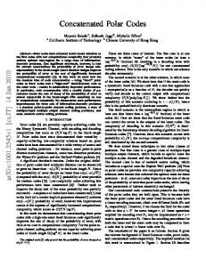
δ1 and δ2 , with 0 < δ1 ≤ δ2 < 1, three sets of channels can be defined: � � (i) 1) good channels, Z WN ≤ δ1 � � (i) 2) intermediate channels, δ1 < Z WN ≤ δ2 , and � � (i) 3) bad channels, Z WN > δ2 .
� � (i) Bhattacharyya parameter Z WN
III. A PPLYING AN AUXILIARY P OLAR C ODE OVER S EMIPOLARIZED C HANNELS
1
δ2
0.8 Frozen bit channels Semipolarized channels Good bit channels
0.6 0.4
δ1
0.2 0
0
1 000
2 000
3 000
4 000
Channel index Figure 2: Sorted Bhattacharyya parameters for N = 4096.
+K2 , the The total encoding rate is given by Rtotal = K1N 1 auxiliary polar code has a rate Rpolar1 = K N1 and the inner +N1 polar code has a rate Rpolar2 = K2N . The corresponding decoder is shown in Fig. 3a. It is an extended version of the conventional BP decoding factor graph. The BP decoder (or the factor graph) of the auxiliary polar code is connected to the leftmost stage of the BP inner polar decoder. The decoder can be also seen in Fig. 3b in a more abstract form. The decoding process works as follows: 1) The inner BP polar decoder receives the channel output vector Lch , then the R2 -messages propagate from left to right, then the L2 -messages propagate from right to left until reaching stage 1, where R2 and L2 represent the R- and L-messages of the inner BP decoder. 2) LLR-messages L2i,1 are passed through the deinterleaver, and the output �is passed�to the BP polar decoder of the auxiliary code L1i,n1 +1 . F2 3) The BP decoder of the auxiliary polar code then per auxiliary inner forms one BP iteration (i.e., one L1 -messages propaga F1 N1 N1 N1 N N tion and one R1 -messages propagation), where R1 and G2 π G1 X N L represent the R- and L-messages of the auxiliary BP }K1 1 K decoder, respectively. K2 4) Next, the LLR-messages at the rightmost stage of the auxiliary BP decoder (R1i,n1 +1 ) are passed through the Figure 1: Proposed encoder. interleaver, and the output is passed � to �the BP polar decoder of the inner polar code R2i,1 . One inner The semipolarized channels, upon which the auxiliary polar code BP iteration is followed by one auxiliary code BP code is applied, are the channels with � � intermediate Bhatiteration until reaching a maximum number of iterations. (i) tacharyya parameter value Z WN as shown in Fig. 2 ˆ as 5) A hard decision is taken to estimate the message u following the basic setup of [6]. Although the Bhattacharyya follows parameter is an error probability measure under sequential a) The LLRs of the estimated message at the input of decoding [1], it turns out that, empirically, it is still a suitthe auxiliary polar code able measure for selecting semipolarized channels under BP L(ˆ u1i ) = L1i,1 + R1i,1 (5) decoding as proposed in [6]. For a specific set of thresholds
(6)
L(ˆ u2i ) = L2i,1 + R2i,1
Recall that, the computational complexity of a polar BP decoder is proportional to the number of PEs in the respective factor graph. The polar factor graph consists of log2 (N ) stages, with N/2 processing elements per stage. Thus, a total of log2 (N ) · N2 processing elements per factor graph. Throughout this paper, the channel used is an AWGN channel, the modulation is BPSK, the total code rate R = 0.5 and polar codes are constructed based on Arıkan’s Bhattacharyya bounds [1] of bit channels designed at SNR of Es /N0 = 0 dB. Frozen bit channel Semipolarized bit channel Good bit channel
π
chosen in the same manner as they were chosen in [6], using (i) the Bhattacharyya parameter value Z(WN ). The encoder of this new, extended setup is shown in Fig. 5. 10−3
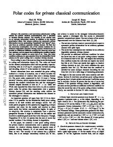
N = 4096 polar BP N = 4096 polar augmented with N1 = 256 polar
10−4 BER
b) The LLRs of the estimated message at the input of the inner polar code
10−5
10−6
10−7
2
2.2
2.4
2.6 Eb N0
Lch
2.8
3
3.2
[dB]
Figure 4: BER-curves of the different setups (N = 4096), compare to Tab. I. Table I: Simulation parameters used for different setups.
π −1
Setup
(a) Factor graph of the iterative decoder. R1i,n1 +1
N1
N
π
auxiliary polar 1 N1
1
R2i,1
inner polar 2 N
π −1
Fi
Ni
F1 = 128 F2 = 1920
N1 = 256 N2 = 4096 N = 4096
F1 = 128 F2 = 960 F3 = 448
N1 = 256 N2 = 2048 N3 = 1024 N = 3072
i
Lch
2
K1 = 128 K2 = 960 K �3 = 448 K = Ki = 1536 i
3 L1i,n1 +1
Ki K1 = 128 K� 2 = 1920 K = Ki = 2048
K1,2,3,4 = 64 K5,6,7,8 � = 448 K = Ki = 2048
N1,2,3,4 = 128 N5,6,7,8 = 1024 N = 4096
F1,2,3,4 = 64 F5,6,7,8 = 448
i
L2i,1
(b) Information flow, simplified (left) and detailed (right).
Figure 3: BP information flow of the combined inner and auxiliary polar decoder. One setup (setup 1) is proposed in this section, with code parameters given in Tab. I and structure described in Fig. 1. A BER performance comparison between the N = 4096 polar code under conventional BP decoding and setup 1 is shown in Fig. 4. A 0.3 dB coding gain is achieved at BER of 10−5 on the “small” expense of computational complexity as shown in Tab. II, due to the introduction of the auxiliary polar code. IV. C OUPLING F OR F LEXIBLE L ENGTH P OLAR C ODES The proposed setup of the previous section can be extended to accommodate an extra inner polar code. Thus, the new setup will consist of two inner polar codes connected, or coupled, through one short auxiliary polar code, which is also used to protect the information bits transmitted on the semipolarized bit channels of the two inner polar codes; this is what we refer to as “parallel” augmentation. The semipolarized channels are
Table II: Number of processing elements per setup. Setup N = 4096 polar BP 1 2 3
Number of PEs =
�
i
log2 (Ni ) ·
Ni 2
24576 (reference) 25600 17408 22272
Note that, the total number of transmitted bits is N = N2 + N3 , given that N2 , N3 > N1 , where N1 is the code length of the auxiliary polar code. The total number of information bits conveyed per codeword is K = K1 + K2 + K3 . Thus the total K1 + K2 + K3 encoding rate is Rtotal = , the auxiliary polar N2 + N3 K1 code has a rate Rpolar1 = , the first inner polar code has a N1 N1 K2 + 2 rate Rpolar2 = and the second inner polar code has N2 N1 K3 + 2 a rate Rpolar3 = . The decoding algorithm is similar N3 to that of the setup in the previous section, as depicted in Fig. 6.
Figure 5: Encoder of the proposed flexible length code. The proposed setup (setup 2) saves a noticeable computational complexity when compared to the conventional BP decoding of the N = 4096 polar code, as can be seen in Tab. II. The above setup can be used to produce modified polar codes with flexible codeword lengths N �= 2n , mitigating the code length constraint � � due to the used kernel (Arıkan’s 2 × 2 1 0 kernel F = [1]). This may prove to be useful when 1 1 proposing polar codes, or, more precisely, “polar-like” codes for communications standards. The same concept can be used to couple an arbitrary number of inner polar codes, which we refer to as “parallel augmentation”. Thus, large codes can be built based on small polar codes, e.g., four inner polar codes (5 ≤ i ≤ 8) are coupled with four short auxiliary polar codes (1 ≤ i ≤ 4) in a ring like structure, as shown in Fig. 8. Tab. I shows the full code parameters of this setup (setup 3). Finally, Fig. 9 shows a BER performance comparison between the N = 4096 polar code under conventional BP decoding and setup 3 (note that setup 3, also, has an effective codeword length of N = 4096). Although the BER performance of both setups is similar, setup 3 has lower overall computational complexity as shown in Tab. II. Thus, the performance of a polar code of length N = 4096 can be approached by four blocks of length N = 1024, saving in computational complexity. Again, the effect of the auxiliary polar codes on the BER is illustrated in Fig. 9 by the green (uncoupled, no auxiliary polar codes used) and red curves (coupled). Similar results and behavior is achieved in [15],
Frozen bit channel Semipolarized bit channel Good bit channel
Lch N2 π
π −1 Lch N3
(a) Iterative decoder of the proposed flexible length code. N1 /2
π
N2
N1
auxiliary polar 1 N1
N1
Lch
inner polar 3 N3
Lch
N2
N1 /2
N3
π
inner polar 2 N2 N1 /2
−1
N3
N1 N1 /2
(b) Information flow, simplified (left) and detailed (right).
Figure 6: BP information flow in the decoder of the flexible length code. N = 4096 polar BP N2 = 2048 and N3 = 1024 polar, not connected (N = 3072) N2 = 2048 and N3 = 1024 polar, connected through N1 = 256 polar (N = 3072)
10−3
10−4 BER
Finally, for N2 �= N3 , implementing flexible length codes become possible. Tab. I shows the full code parameters for one example of the proposed scheme (setup 2). The effective code length of setup 2 is N = 3072 bits. Fig. 7 shows that setup 2 outperforms the conventional polar code under BP decoding in terms of BER, even with a shorter code length N . The effect of the auxiliary polar code on the BER is shown in Fig. 7: keeping the individual polar codes of lengths N2 , N3 separate (green BER curve) is much worse than connecting them through the auxiliary polar code (dotted red curve), i.e., the information flow in the iterative decoder through coupling works. F2 inner N1/2 N2 N2 G2 auxiliary K2 F1 N1 N 1 � π N X G 1 }K1 F3 K inner N1/2 N3 N3 G3 K3
con
nec
10−5
10−6
BP
2
2.2
2.4
con
nec
ted
ted
2.6 Eb N0
not
2.8
3
3.2
[dB]
Figure 7: BER-curves of the different setups (compare to Tab. I).
where systematic polar codes are concatenated in parallel, akin to the structure of classic turbo-codes [16]. N5 N1
N8
R EFERENCES
N2 N6
N3 N4
N=
8 �
Ni
N7
i=5
Figure 8: Four inner polar codes of lengths N5,6,7,8 coupled, in a ring like structure, through four auxiliary polar codes of lengths N1,2,3,4 . N = 4096 polar BP Four Ni = 1024 polar, not connected (N = 4096) Four Ni = 1024 polar, connected through four Ni = 128 polar (N = 4096)
10−2
BER
10−3
10
not
con
nec
ted
−4
con
nec
10−5
10−6
BP
2
2.2
2.4
2.6 Eb N0
2.8
to better protect the semipolarized bit channels, leading to a coding gain of 0.3 dB at a BER of 10−5 under BP decoding. Moreover, several polar codes were connected through auxiliary polar codes, facilitating flexible length codes with similar BER performance at lower computational complexity when compared to the conventional BP decoder of a single, longer polar code. The successful coupling of short-length polar codes indicates that the more general concept of spatially coupling may be applicable to polar codes in the same sense as has been successfully applied to LDPC codes [17] and turbo-like codes [18] already.
ted
3
3.2
[dB]
Figure 9: BER-curves of the different setups (N = 4096), compare to Tab. I. V. C ONCLUSION We introduced the idea of augmenting a finite length “inner mother” polar code by a short auxiliary (or “outer”) polar code
[1] E. Arıkan, “Channel polarization: A method for constructing capacityachieving codes for symmetric binary-input memoryless channels,” IEEE Transactions on Information Theory, vol. 55, no. 7, pp. 3051–3073, July 2009. [2] K. Niu, K. Chen, J. Lin, and Q. T. Zhang, “Polar codes: Primary concepts and practical decoding algorithms,” IEEE Communications Magazine, vol. 52, no. 7, pp. 192–203, July 2014. [3] I. Tal and A. Vardy, “List decoding of polar codes,” IEEE Transactions on Information Theory, vol. 61, no. 5, pp. 2213–2226, May 2015. [4] E. Arıkan, “A performance comparison of polar codes and Reed-Muller codes,” IEEE Communications Letters, vol. 12, no. 6, pp. 447–449, June 2008. [5] J. Xu, T. Che, and G. Choi, “XJ-BP: Express journey belief propagation decoding for polar codes,” in IEEE Global Communications Conference (GLOBECOM), Dec 2014, pp. 1–6. [6] J. Guo, M. Qin, A. G. i Fàbregas, and P. H. Siegel, “Enhanced belief propagation decoding of polar codes through concatenation,” in IEEE International Symposium on Information Theory, June 2014, pp. 2987– 2991. [7] A. Elkelesh, M. Ebada, S. Cammerer, and S. ten Brink, “Improving belief propagation decoding of polar codes using scattered EXIT charts,” in IEEE Information Theory Workshop (ITW), September 2016. [8] L. Zhang, Z. Zhang, and X. Wang, “Polar code with block-length N = 3n ,” in International Conference on Wireless Communications Signal Processing (WCSP), Oct 2012, pp. 1–6. [9] K. Niu, K. Chen, and J. R. Lin, “Beyond turbo codes: Rate-compatible punctured polar codes,” in IEEE International Conference on Communications (ICC) 2013, June 2013, pp. 3423–3427. [10] V. Miloslavskaya, “Shortened polar codes,” IEEE Transactions on Information Theory, vol. 61, no. 9, pp. 4852–4865, Sept 2015. [11] I. Tal and A. Vardy, “How to construct polar codes,” IEEE Transactions on Information Theory, vol. 59, no. 10, pp. 6562–6582, Oct 2013. [12] P. Trifonov, “Efficient design and decoding of polar codes,” IEEE Transactions on Communications, vol. 60, no. 11, pp. 3221–3227, November 2012. [13] Y. S. Park, Y. Tao, S. Sun, and Z. Zhang, “A 4.68Gb/s belief propagation polar decoder with bit-splitting register file,” in Symposium on VLSI Circuits, June 2014, pp. 1–2. [14] A. Pamuk, “An FPGA implementation architecture for decoding of polar codes,” in 8th International Symposium on Wireless Communication Systems (ISWCS), Nov 2011, pp. 437–441. [15] D. Wu, A. Liu, Y. Zhang, and Q. Zhang, “Parallel concatenated systematic polar codes,” Electronics Letters, vol. 52, no. 1, pp. 43–45, 2016. [16] C. Berrou, A. Glavieux, and P. Thitimajshima, “Near shannon limit errorcorrecting coding and decoding: Turbo-codes. 1,” in IEEE International Conference on Communications (ICC), vol. 2, May 1993, pp. 1064–1070 vol.2. [17] A. J. Felstrom and K. S. Zigangirov, “Time-varying periodic convolutional codes with low-density parity-check matrix,” IEEE Transactions on Information Theory, vol. 45, no. 6, pp. 2181–2191, Sep 1999. [18] S. Moloudi, M. Lentmaier, and A. G. i Amat, “Spatially coupled turbo-like codes,” in 8th International Symposium on Turbo Codes and Iterative Information Processing (ISTC) 2014, August 2014.