FLEXIBLE ROUTE LOOKUP USING RANGE SEARCH Andreas Ehliar Dept. of Electrical Engineering Link¨oping University S-581 83 Link¨oping, Sweden
[email protected] ABSTRACT The rising number of entries in an Internet routing table is placing higher demands route lookup engines. This paper presents a hardware implementation of a route lookup engine based on a combination of range search and linear search. The route lookup engine is constructed using a pipeline of identical search units. The lookup engine can be configured with more than one routing table allowing for simultaneous searches in more than one table. The worst case memory usage is independent of the distribution of prefixes in the routing table. Updates to the routing tables are merged together to minimize the number of updating cycles. KEY WORDS High Speed Internet, Router, Route lookup, Hardware implementation
1
Introduction
One of the critical components in a high speed router is the route lookup engine. As the Internet is growing, higher demands are placed on this component. Specifically, the size of the routing tables and the number of lookups performed per second is increasing. The number of prefixes in routing tables on the Internet is increasing all the time. At the time of writing, a routing table for a typical Internet router can contain over 210000 IPv4 prefixes [1]. There is a clear trend that the number of prefixes will continue to increase in the future as well. The bandwidth of the Internet is also rapidly increasing placing higher demands on the route lookup engine. For each packet the route lookup engine has to do at least one lookup. For certain scenarios more than one lookup may have to be performed using different lookup tables. An example of this could be a multicast environment where the source address has to be validated as a valid sender before a packet is marked as valid to send.
1.1
Longest prefix match
A network prefix in an IPv4 routing table consists of 32 bits of address information and a length field indicating the number of significant bits in the address field. A network
Dake Liu Dept. of Electrical Engineering Link¨oping University S-581 83 Link¨oping, Sweden
[email protected] prefix is usually written in the form 10.5.3.0/24, where /24 indicates that only the first 24 bits in the IP address are significant. Associated with each network prefix is a destination port for packets with a destination address matching this network prefix. The route lookup is complicated by the fact that one destination address can match several prefixes. In this case, the lookup engine should select the matching network prefix with the highest number of significant bits. This is called longest prefix match. As an example, consider a routing table with two prefixes, 10.0.0.0/8 and 10.120.50.0/24. The first entry has 8 significant bits and the second entry has 24 significant bits. A packet destined for 10.120.50.34 will match both entries but since the second entry has more significant bits, that entry should be consulted for the destination port.
1.2
Previous work
There are many algorithms available for longest prefix match both in software and hardware. In software for example, Patricia tries [2] as used in BSD Unix may be used. Another trie based solution is LC-Tries [3]. A solution based on range trees is outlined in [4]. A thorough survey of algorithms for longest prefix match appears in [5]. In hardware one popular method is to use a ternary content addressable memory (TCAM) [6] for route lookup. The advantage of a TCAM is ease of use whereas the drawback is a high power consumption and a large chip area compared to a solution that uses SRAM or DRAM. The TCAM is also deterministic in the sense that the maximal number of entries that can be stored in a TCAM is known from the beginning and does not vary depending on the distribution of prefixes in the routing table. One hardware based solution utilizes the fact that most entries in a routing table have 24 significant bits and use one memory for all 24 bit long prefixes that can index into another memory if a certain prefix has more than 24 significant bits [7]. This will not work if the routing table has too many prefixes with more than 24 significant bits. Software based solutions based on trees can easily be adapted to a high performance hardware solution splitting the tree over several memories in different pipeline stages. The problem with this solution is that the memory requirements for each stage in the pipeline varies depending on the
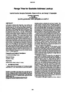
Normal prefix table 0.0.0.0/0 10.0.0.0/8 10.10.1.0/24 10.10.2.0/24 Range table 9.255.255.255 10.10.0.255 10.10.1.255 10.10.2.255 10.255.255.255 255.255.255.255
→ → → →
Port 1 Port 2 Port 3 Port 4
→ → → → → →
Port 1 Port 2 Port 3 Port 4 Port 2 Port 1
Prefix bits 0 8 16 16 Prefix bits 0 8 24 24 8 0
Range table 9.255.255.255 10.9.255.255 10.10.0.255 10.10.1.255 10.10.2.255 10.10.255.255 10.255.255.255 255.255.255.255
→ Port 1 → Port 2 → Port 5 → Port 3 → Port 4 → Port 5 → Port 2 → Port 1
Prefix bits 0 8 16 24 24 16 8 0
Remarks New Modified
New
Figure 3. The range table from figure 1 after the addition of the prefix 10.0.0.0/16 with a destination port of 5.
Figure 1. Prefix table and range table.
2 > 10.10.1.255
> 10.10.0.255
> 10.255.255.255
3
1
> 9.255.255.255
1
2
> 10.10.2.255
4
2
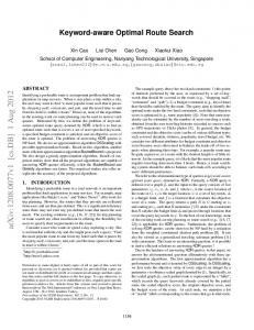
Figure 2. A binary range search tree for the prefix table.
distribution of prefixes in the routing table. There are a number of different solutions to this problem. The easiest is to accept the problem and analyze the memory sizes required in the different stages and dimension them appropriately for typical routing tables [8]. Another promising solution is to dynamically allocate memory via a crossbar to each pipeline stage as proposed in [9].
The basic idea behind the range search algorithm is to divide the routing table into ranges. For example, a prefix 10.0.0.0/8 can be represented as the range of addresses between 10.0.0.0 and 10.255.255.255, including the start and end points. An example of how to transform a table with prefixes into a range table is given in figure 1. Each entry in the range table consists of the last address of that range, the number of significant bits for the prefix responsible for that particular range, and the destination port. The starting point of each range is implicit as the next address after the previous range. The main idea behind this transformation is that it is possible to sort the entries in a range table since all bits in the address field of a range table are always significant. After this transformation is done, a binary search can be conducted on the table as illustrated in figure 2. In the rest of this paper, an entry refers to one line in the range table whereas a prefix refers to the network prefix which may correspond to many entries in the range table.
2.1 1.3
Longest prefix match using range search
Adding a prefix to the table
Our solution
In this paper we propose a solution based on range search with a performance limited by the cycle time of SRAM. An advantage of our scheme is that the maximum number of prefixes that can be stored in the routing table is known beforehand and it is not dependant upon the distribution of prefixes in the routing table. Another advantage of our approach is that the solution allows for more than one search table that can be searched simultaneously. In order to balance the range tree quickly, hardware is used in order to facilitate memory copying. The rest of this paper is organized as follows, section 2 describes how to perform the longest prefix match using range search, section 3 describes our hardware based lookup engine, section 4 describes how to manage the routing table in our solution, section 5 describes a proof of concept implementation, section 6 describes the performance of the lookup engine, section 7 describes possible future improvements, and section 8 provides concluding remarks.
If an IPv4 prefix is added to the routing table a maximum of two entries has to be added to the range table. One entry represents the first address in the IPv4 prefix and one entry represents the last address in the IPv4 prefix. It is therefore always possible to store N IPv4 prefixes in a range table with 2N entries. (This means that the capacity of the routing table can be specified without any reservations based on the distribution of prefixes.) However, after adding the start and end address, some entries located between the start and end of the new prefix might have to be changed. For example, if we want to add a prefix 10.10.0.0/16 to the routing table with a destination port of 5, the routing table will be updated as shown in figure 3. If a prefix with L significant bits is added to the routing table, all entries between the start of the range and the end of the range need to be updated with a new destination port if the prefix they belong to have less than L prefix bits. At the same time, the prefix bits of the updated entries are
Range table 10.9.255.255 10.10.0.255 10.10.1.255 10.10.2.255 10.10.255.255 255.255.255.255
Prefix bits → → Port 1 → Port 5 → Port 3 → Port 4 → Port 5 → → Port 1
0 16 24 24 16
Remarks Deleted Modified
Range Search
Search Unit
Search Unit
Search Unit
Figure 5. An illustration of the search pipeline. The range search unit narrows the search and the search units perform the linear search. Deleted
0
SearchIP
Figure 4. The range table after deleting 10.0.0.0/8. Index Range Table Memory
set to L. If a prefix (with L significant bits) is updated with a new destination, all entries between the the first and last entry of this prefix, including the last entry has to be updated if the prefix bits of this entry is set to L. Similarly, the deletion of a prefix is managed by removing the start and end of the range (unless they are in use by another prefix) and modifying the prefix length and destination port of all entries inbetween to correspond to the correct prefix. This is illustrated in figure 4.
3
Hardware solution
Searching for the destination port for a given address is just a matter of finding the first entry in the table where the address is larger than or equal to the given address. However, a linear search is not feasible for anything but the smallest routing table. To increase performance it is possible to perform a binary range search as illustrated in figure 2. The drawback of this approach is that larger and larger memories are needed for each stage in the pipeline making the floorplanning cumbersome. In this paper we propose a solution that utilize at first a small binary range search to narrow the search unit and after that perform a linear search in a number of identical search units. The basic idea is illustrated in figure 5 and the contents of a search unit is shown in figure 6. In practice, the search unit memory is synchronuous and for performance reasons flip flops might be added after the memory and before the comparator. For clarity, these details are omitted in this paper but they are present in our RTL implementation. The search units responsible for the pipelined linear search contain a small memory with a number of routing entries in it. The unit responsible for the initial range search will pass an index to the linear search unit which points to one entry in the linear search unit’s memory. Suppose that an application need to perform not only one but two types of searches per packet. For example a router that need to perform some sort of QoS depending on the source address. This could be solved by constructing two pipelines as described above. However, the requirements on the amount of entries in the source address table and the destination address table is likely to vary widely
DestPort
Destination
>
SearchIP < IP
IP
0 1
Found
Figure 6. Outline of a search unit. The found signal is set to 1 once a valid destination has been found. (The parts that are responsible for updates of the range table has been omitted for clarity.)
depending on where the application is installed. It would be desirable to be able to allocate memory for each pipeline from a common pool. One way to allow this dynamic memory allocation is shown in figure 7. The idea is to construct another range search unit and install muxes in the search unit pipeline so that each search unit can be allocated to any pipeline. This can of course be generalized to more than two search pipelines as well.
4
Management of the range table
The linear search part of the combined search pipeline is logically a matrix with M columns and R rows. Each element of the matrix contains a range entry. A row corresponds to one of the search units in figure 6 and a column corresponds to one memory position in the search units. Each search unit has a hard coded number that contains its position in the pipeline. These commands are used to manage the range table: • WRITE(m,j,ENTRY) Write ENTRY to memory position m if the search unit number is j. • READ(m,j) Read out the entry stored in memory position m if the search unit number is j. • NEWRANGE(m,ENTRY) Update the binary range search table in position m with ENTRY.
Data
Range Search
Search Unit
Search Unit
Search Unit
Data feedback from next stage
Search Unit Memory Mux
Range Search
Memory
Output Mux
Figure 7. The architecture as extended to two parallel searches with a pipeline dynamically partitioned to different search units. Commands
An ENTRY consists of three fields, an IP address, a prefix length and the destination port for destination addresses that are less than or equal to the IP address. The prefix length field is not required for searching the table but it will make management of the table easier. In addition, the linear search pipeline will not function correctly unless all entries in one column are sorted with the smallest value located in row 1. This represent a problem once the routing table has to be updated. In order to insert an entry, a potentially very large number of entries have to be rearranged. To improve the situation, five new commands are added to the search units to improve update performance.
Figure 8. An outline of the updating logic of a search unit.
2. tmp2 = READ(i,R-1) Read out new range limit in column i. 3. READCOL(i+1) Prepare for the FORWARD command. 4. FORWARD(i+1,1,R) Shift column i+1 forward one step. 5. WRITE(i+1,1,tmp) Update first entry of column i+1 with this value.
• READCOL(m) Read out memory position m to the output flip flops of the search unit.
6. NEWRANGE(i,tmp2) Update the binary range search table with the new end of column i.
• FORWARD(m,j,k) Write the data from the output flip flops of the previous search unit to memory position m if the search unit number is greater than or equal to j and less than or equal to k.
7. READCOL(i) Prepare for the FORWARD command. 8. FORWARD(i,j,R) Insert space for the entry in column i at row j. 9. WRITE(i,j,ENTRY) Insert the entry at position j in column i.
• BACKWARD(m,j,k) Write the data from the output flip flops of the next search unit to memory position m if the search unit number is greater than or equal to j and less than or equal to k.
Other examples of these commands are illustrated in figure 9.
• WRITECOL(m) Write the data from the output flip flops of this search unit to memory position m.
4.1
• CHANGECOL(m,j,k,len,newlen,p) If len is equal to the prefix length in the output flip flops of the search unit, change the destination port in memory position m to p and the prefix length to newlen. The search unit number has to be larger than or equal to j and smaller than or equal to k. The logic necessary to support these commands is outlined in figure 8. By combining READCOL with the other commands it is possible to shift an entire column forward or backward using only two commands or move the entire contents of one column to another column. For example, if an entry is supposed to be inserted into column i, row j, and the nearest free slots are located at the end of column i+1, the following commands have to be executed: 1. tmp = READ(i,R) Read out the last entry in column i.
Changing entries in the range table
In order to update the range table efficiently it is better to update the range table with a large number of prefixes simultaneously. In this way the number of cycles used for updating is reduced. The main idea is also to perform updates in an incremental fashion so that it is possible to temporarily halt an update if a search request is issued to the lookup engine. As a first example we will consider only the case where destination ports for prefixes are changed. As outlined in section 2.1, it is necessary to search the range table between the first address of the network prefix and the end address of the prefix address and change the destination port of all entries with the same prefix length as that of the updated prefix. This can be accomplished using a combination of READCOL and CHANGECOL commands Assume that the first address of the prefix has been added at memory position m in search unit j and that the
1
2
3
4
5
6
7
8
M
1
4.2
Removing prefixes from the table
Deleting an entry is not a problem, it is only a matter of shifting the entries below the removed entry one step backward with READCOL/BACKWARD and possibly issuing a NEWRANGE command if the last entry in a column was removed. Since all ranges belonging to the deleted prefix now belong to another prefix, the prefix length and destination ports must be changed accordingly. This is done using READCOL and CHANGECOL as described in the previous section.
2
3
4
4.3 5
Figure 9. The data movements as a result of the following commands: READCOL(1);FORWARD(1,3), READCOL(3);BACKWARD(3,3), READCOL(5);WRITECOL(8).
end address is added to memory position n in search unit k. 1. READCOL(m) Prepare for CHANGECOL. 2. CHANGECOL(m,j+1,R,len,len,p) Change all entries below the first address. 3. For every column, i = m + 1, m + 2, . . . , n − 1, between the start address and the end address: • READCOL(i) Prepare for CHANGECOL. • CHANGECOL(i,1,R,len,len,p) 4. READCOL(m) Prepare for CHANGECOL. 5. CHANGECOL(m,1,k,len,len,p) Change all entries above the end address. In the worst case, we need to consider every column. By updating several prefixes at once we can drastically reduce the impact of the worst case since we can avoid overlapping CHANGECOL commands. If for example the destination port of 10.0.0.0/8 and 10.10.0.0/16 are modified, it is not necessary to perform the CHANGECOL responsible for 10.0.0.0/8 on the columns located between the start and end of 10.10.0.0/16 because those columns cannot contain any entries belonging to 10.0.0.0/8. Each modification can introduce a maximum of two regions with change commands. A region can span several columns but the maximum number of such spans is limited by the number of columns. The maximum number of CHANGECOL commands required by n prefix updates is thus 2n+2M where M is the number of memory positions in a search unit.
Adding prefixes to the table
Inserting entries is a problem however. The worst case for inserting one entry involves shifting a large number of entries around. For example, if an entry has to be added in column 1 and the nearest free slot is located in column M , up to M READCOL/FORWARD/WRITE commands has to be inserted into the pipeline. If we want to add up to R − 1 entries, a maximum of (M ) · (R − 1) READCOL/FORWARD/WRITE commands have to be executed. However, as soon as R FORWARD commands have to be executed on one column, this means that the entire column is supposed to be moved to the next column. It is now possible to replace the READCOL/FORWARD/WRITE commands with a single READCOL/WRITECOL pair. This means that there will never be a need for more than R − 1 READCOL/FORWARD/WRITE commands per column. This will drastically reduce the worst case for additions to the table. The worst case behavior using these commands are still not very good and if an update approaching worst case behavior is encountered it might make sense to simply rewrite the entire routing table.
5
Implementation
We have implemented a C model of this system to verify that the concept works. We also implemented an RTL model of the lookup engine described in this paper and tested it on an FPGA board with a Virtex-II 4000. The maximum clock frequency obtained on the FPGA was 100 MHz but an ASIC based solution based on a modern process should be much faster.
6
Performance
One search or update command can be inserted into each pipeline at each clock cycle. This means that the performance of our proposed solution will be similar to other SRAM based solutions that are limited by the frequency of on-chip SRAM. As an example, if a clock frequency of 500 MHz is used, a router with 16 x 10 gigabit ports can be managed by our lookup engine (assuming a minimum packet length of 40 bytes).
However, since the architecture is intended for an application where several searches are issued simultaneously to the lookup engine a straightforward comparison with other solutions supporting only one search at a time is somewhat misleading. The memory consumption for a routing table capable of storing 250000 IPv4 prefixes with a destination port field of 12 bits will be 25 Mbit. If the memory in the search unit contains 8192 entries, 61 search units will be required to store this table. The total latency of this lookup engine will be 61 cycles plus approximately 26 cycles for the initial binary range search.
7
Discussion and Future Work
There is a tradeoff between the search unit memory size and the length of the pipeline that has to be decided upon. If the pipeline is longer, updates are typically cheaper whereas the area and power consumption will increase as more memories are added. Smaller memories also mean that the partitioning of memory to each search pipeline can be done with a finer granularity. Smaller memories are also faster than larger memories. As a comparison to CAM memories that are commonly used in commercial solutions, our solution has longer latency for lookups but smaller power consumption due to the usage of SRAM instead of specialized CAM memories. A drawback of this architecture as compared to a CAM memory is that it is expensive to add prefixes to the routing table one prefix at a time. This is mitigated by merging requests and adding them simultaneously. The worst case performance of additions to the routing table can still be quite low because the entire routing table has to be rewritten. The architecture can be extended to allow other address formats than IPv4. IPv6 could be supported either by increasing the width of the memories or by storing the IPv6 addresses in several consecutive pipeline stages. Other address formats like MPLS or Ethernet addresses could easily be added by allowing for routing tables with exact matches only. Finally, a more flexible architecture for interconnection than the mux based interconnection in figure 7 should be investigated. Another thing that would be interesting to investigate is if other lookup engines could benefit from specialized hardware to ease routing table updates. We also propose that a specialized small CPU should be added to this system that handles the updates to the routing table in order to offload the main CPU in the router.
8
Conclusions
The architecture has a number of important features. It is SRAM based and limited by the speed of embedded SRAMs.
The main advantages are the usage of specialized hardware to reduce the cost of keeping the range tree balanced and the possibility of issuing more than one search request simultaneously to this table. The address format can be extended to support both IPv4, IPv6, Ethernet addresses, and MPLS although only IPv4 has been tested in an RTL model. The memory usage of the architecture is deterministic regardless of the distribution of the routing prefixes. The execution time for updates to the routing table is limited to a reasonable upper bound by merging updates and performing them simultaneously. The design can be scaled by adding more search units or increasing the memory size of a search units. Finally, the design is suitable for a system with several lookup tables where it is important to be able to perform searches in parallel without having to waste memory.
References [1] Growth of the BGP table - 1994 to Present http://bgp.potaroo.net/ [2] Sklower, K, A Tree-Based Packet Routing Table for Berkeley UNIX, USENIX Conference Proceedings, Dallas, TX, 1991, 93-104 [3] Nilsson, S.; Karlsson, G., IP-address lookup using LCtries, Selected Areas in Communications, IEEE Journal on, Vol.17, Iss.6, Jun 1999, 1083-1092 [4] Subhash Suri; Varghese, G.; Warkhede, P.R., Multiway range trees: scalable IP lookup with fast updates Global Telecommunications Conference, 2001. GLOBECOM ’01. IEEE, Vol.3, 2001, 1610-1614 [5] Ruiz-Sanchez, M.A.; Biersack, E.W.; Dabbous, W., Survey and taxonomy of IP address lookup algorithms Network, IEEE, Vol.15, Iss.2, 2001, 8-23 [6] Fast routing table lookup using CAMs McAuley, A.J.; Francis, P. INFOCOM ’93. Proceedings.Twelfth Annual Joint Conference of the IEEE Computer and Communications Societies. Networking: Foundation for the Future. IEEE, Vol. 3, 1993, 1382-1391 [7] Gupta, P.; Lin, S.; McKeown, N., Routing lookups in hardware at memory access speeds, INFOCOM ’98. Seventeenth Annual Joint Conference of the IEEE Computer and Communications Societies. Proceedings. IEEE, Vol.3,1998,1240-1247 [8] Tomas Henriksson and Ingrid Verbauwhede, Fast IP address lookup engine for SoC integration, Proceedings of Design and Diagnostics of Electronics, Circuits and Systems, Brno, Czeck Republic, 2002, 200-210 [9] Florin, B.; Rajgopal, S.; Lun-Bin, H.; Richardsson, N., A scalable IP lookup ASIC for OC-768 links, 3rd Workshop on Application Specific Processors,Stockholm, Sweden, 2004, 35-40