th
The 14 World Conference on Earthquake Engineering October 12-17, 2008, Beijing, China
FLEXURAL ENHANCEMENT OF RC COLUMNS WITH FRP 1
2
M.Sarafraz and F.Danesh 1
2
Phd student, Dept. of Civil Engineering ,KNT University of Technology, Tehran. IRAN Assistant Professor, Dept. of Civil Engineering ,KNT University of Technology, Tehran. IRAN Email:
[email protected],
[email protected]
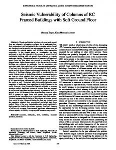
ABSTRACT : The application of composite materials has been developed in strengthening and retrofitting of concrete structures through recent years, so that many of concrete structures would be strengthened by these materials. one of theses applications are FRP material used in strengthening and retrofitting of reinforced concrete columns. Results of studies have shown that wrapping of reinforced concrete columns with FRP caused increasing of ductility and compressive strength of RC columns. Since, almost all RC columns are affected by axial force and moment bending. Studies of interaction curve of wrapped RC columns with FRP shows that just compressive control region in interaction curve enhance and wrapping of columns with FRP has no affected on tension control region of RC columns. The objective of this research program is to enhancement flexural strength of RC columns with high and low axial steel content when retrofitted by FRP system that oriented in the direction of applied axial load. one reinforced concrete column designed and modeled under lateral cyclic loading and constant axial load. it is demonstrated analytically that it is possible to strengthen the flexural resistance of RC columns.
KEYWORDS:
FRP, Strengthening, Column,NSM
1. INTRODUCTION Failure of concrete columns may result from crushing of the concrete due to either a lack of confinement or the fracture of the transverse hoop reinforcement, and buckling of the longitudinal reinforcement [1]. For columns, the maximum moments and strains occur at the ends of the column. In the event of an earthquake, all elements outside the plastic hinge zone of column may remain elastic. Damage is limited within the plastic hinge zone. Fiber reinforced polymer (FRP) reinforcement stands today as a viable alternative to conventional types of reinforcement and the use of FRP is gaining interest in the construction practice worldwide. The seismic retrofitting of chimneys, bridge piers, and columns using light, high strength and high durability continuous fiber reinforcement such as aramid, glass, and carbon FRP has been developed and is now entering the stage of practical use[2]. This study proposes a column retrofit technique for strengthening of columns using composite materials systems. To achieve this objective, a strengthening technology called near surface mounted rods is combined with the application of FRP jacketing for providing column end region confinement, increased strength and ductility, and collapse prevention. To increase flexural capacity of columns, the technique referred to as Near-Surface Mounted (NSM) FRP rods is proposed. Embedment of the rods is achieved by grooving the surface of the member to be strengthened along the desired direction. Continuity with foundation, slab or cap beam is obtained by drilling a hole into such member. The groove is filled half way with epoxy paste. The FRP rod is then placed in the groove and lightly pressed, so forcing the paste to flow around the bar and fill completely between the bar and the sides of the groove. The groove is then filled with more paste and the surface is leveled. Details of the final product are shown in Figure 1 [2]After completing the installation of NSM reinforcement, an FRP jacket is provided with the purpose of confining both concrete and rods.
th
The 14 World Conference on Earthquake Engineering October 12-17, 2008, Beijing, China
Figure 1: Installation of Near Surface Mounted Rods Followed by FRP Jacketing[2]
2. HISTORY OF THE TECHNOLOGY The use of NSM reinforcement was developed in Europe for strengthening of RC structures in the early 1950s. In 1948, an RC bridge deck in Sweden needed to be upgraded in its negative moment region due to an excessive settlement of the steel cage during construction [3]. This was accomplished by inserting steel reinforcement bars in grooves made in the concrete surface and filling it with cement mortar (Asplund 1949). More recently, NSM reinforcement has been used to upgrade masonry structures to increase their tensile strength and ductility (Atkinsosn and Schuller 1992).This technology is an effective and economical means of repairing and strengthening low-rise masonry buildings and arch bridges (Garrity 1995). Stainless steel has replaced the original black steel adopted at the onset of the development, while the cementitious grout used for embedding the reinforcement has been partially replaced by epoxy-based grouts. 3.NEAR SURFACE MOUNTED FRP ROD The use of NSM FRP rods increases the flexural and the shear strength of deficient column and can be more convenient than using externally bonded FRP laminates in the negative moment regions of a deck. In this case, the externally bonded reinforcement would be subjected to mechanical and environmental damage and would require protective cover which could interfere with the presence of floor finishes. In Figure 2, the load-moment interaction diagram (P-M diagram) of a rectangular column is shown. In the region between A and B, failure initiates by crushing of the concrete on the compression side of the member; between points B and C, failure initiate by yielding of the tension steel. After the NSM rods are installed, the P-M diagram expands rightward in proportion to the increase of vertical reinforcement ratio (Figure 3) in the tension controlled region. Conversely, with the application of a composite jacket, the capacity of concrete to carry axial load increases as the composite jacket contributes confinement to the cross section (Figure 4). Figure 5 shows that the combination of NSM rods and externally bonded reinforcement enhances the strength of a member, in both compression and tension controlled regions. In addition, the presence of the jacket contributes to the stability of the rods and controls epoxy paste cracking[2].
th
The 14 World Conference on Earthquake Engineering October 12-17, 2008, Beijing, China
Figure 2: P-M Diagram before Strengthening
Figure 4:Installation of Composite Jacket
Figure 3:P-M Diagram after Installation of NSM Rods
Figure 5: Combination of NSM Rods and Composite Jacket
4. OUTLINE OF FE ANALYSIS 4.1.FE Model For analysis, a column was three-dimensionally modeled with respect to the two symmetrical axes. Main rebar and FRP sheet were modeled using eight-node solid elements and concrete was modeled using eight-node and/or six-node solid elements. Stirrups were modeled using embedded rebar elements assuming perfectly bonded between stirrup and concrete and FRP rebar were modeled with two-node truss element(DIANA)[6]. The column has been strengthened with FRP wrap and FRP NSM rod at its side. 4.2.Modeling of Geometrical Discontinuities In order to consider the effects of the geometrical discontinuities such as opening of cracks, slipping of rebar and debonding of FRP sheet and FRP rebar, interface elements were applied, which is in pairs of overlapping nodes with a zero thickness. Failure of the interface element is considered by applying a stress-relative displacement relation to the interface element. In this study, two stress-relative displacement models named as, bond-slip model, and FRP sheet debonding model as shown in Fig6.a were adopted to consider the effects of the opening of dominant cracks, the slipping of rebar, and the peel-off of FRP sheet and FRP rebar ,respectively [4].
th
The 14 World Conference on Earthquake Engineering October 12-17, 2008, Beijing, China
(a) Bond-slip model
(b) FRP sheet and rod debonding model
Figure 6: Stress-relative displacement relations for interface elements Bond-slip model was applied to the interface elements arranged around the main rebar elements along the whole span to consider the slippage between rebar and concrete. The relationship between bonding stress τb and relative displacement S for this model was defined with reference to the CEB-FIP model code [5], 1990, as shown in Fig. 5(a). Relationship between normal stress and normal relative displacement is defined to be linear with a stiffness of 100 MPa/mm, which is the same value as that of the discrete cracking model. FRP debonding model used to simulate debonding behavior of FRP sheet is the model proposed based on the Coulomb friction concept [4]. The criteria for FRP sheet debonding in the normal and plane shear directions are independently defined as follows[4]: σ d > σ d ,max (4.1)
τ d = τ d2− a + τ d2−t > τ d . max
(4.2)
where, σ d ,max is interfacial tensile strength, σ d is applied normal stress, τ d . max is interfacial shear strength,
τ d − a and τ d −t are applied plane shear stress in axial and transverse direction, respectively. Interfacial tensile strength σ d , max was assumed to be equal to the tensile strength of concrete ft because of bonding strength is stronger than the tensile strength of concrete, and normal stiffness k n ,d was set to be 100 MPa/mm similarly to that for the discrete cracking model mentioned above. Shear stiffness k t ,d is assumed to be equal to the normal stiffness k n ,d and interfacial shear strength τ d . max was estimated using the following equation :
τ d . max = 0.92 f c′ ( MPa)
(4.3)
4.3. Modeling of Materials For the compression region of concrete, a parabola-rectangle model was adopted up to 0.35% strain. In the post peak region, soften branch was defined as linearly declining with 5% of initial stiffness until stress reaching to 0.2 f'c. The von Mises yield criterion with an associated flow rule was adopted. In the tensile region, a linear tension-softening model was applied. The smeared crack model was applied to the concrete elements to incorporate the effects of cracking of concrete into the numerical analysis. Shear modulus of the concrete element after crack opening was assumed to be 1% of the initial shear modulus G of concrete. The stress-strain relation for main rebar and stirrup was assumed as following a bilinear isotropic-hardening model. Here, plastic hardening coefficient was assumed to be 1% of the Young's modulus. Yield of rebar and stirrup was controlled following the von Mises yield criterion. FRP sheet and rod was assumed to be linear elastic material until rupture. Here, unidirectional FRP sheet and FRP rod assumed to be an isotropic and homogeneous body, because influence of the stiffness in the transverse direction on the flexural behavior of beams is negligible
th
The 14 World Conference on Earthquake Engineering October 12-17, 2008, Beijing, China
5. ANALYSIS PROGRAM A total of 2 specimens of column with height of 1.5m have been modeled. The details and cross-section of the specimens are illustrated in Fig 7 , concrete with compressive strength of 24 MPa at 28 days has been used. Steel reinforcements D14 (φ14mm) of S400 have been arranged with steel ratio of 0.019. Shear reinforcements of D10 have been located every 10 cm to avoid shear failure. Table 1 summarizes the material properties used for the test beams.
Figure7: Details and cross-section of the specimen (cm) Table 1: Summary of material properties Material Concrete Steel reinforcement
CFRP Sheet
CFRP rod
Property Compressive strength(MPa)
24
Yield strength (MPa)
4000
Tensile strength (MPa)
5000
Diameter(mm)
14
Tensile strength (MPa)
3800
Elastic modulus (GPa)
240
Ultimate strain (%)
1.5
thickness (mm)
0.176
Tensile strength (MPa)
2000
Elastic modulus (GPa)
200
Ultimate strain (%)
1.5
Diameter (mm)
10
th
The 14 World Conference on Earthquake Engineering October 12-17, 2008, Beijing, China
6. ANALYSIS RESULTS Before failure, all the strengthened specimens exhibited bending behavior similar to the unstrengthened specimen. This shows that the FRP reinforcement is unable to contribute to the increase of the stiffness and strength in the elastic domain. However, after cracking, the bending stiffness and strength of the strengthened specimens were seen to increase significantly until failure compared to the unstrengthened specimens. Examining the final failure, the unstrengthened control specimen presented a typical bending failure mode which is proceeded by yielding of the steel reinforcement followed by compression failure of concrete (Figure 8). Failure NSM specimens, occurred through the simultaneous separation of the CFRP reinforcement from the concrete .
Figure 8: result of analysis Fig 9 Shows the compare between forced- displacement curve for before and after retrofitting of column with FRP. This figure shows that retrofitting of column with FRP cause to enhancement of flexural capacity of reinforced concrete column.
Figure 9: Comparison of load-deflection curve
th
The 14 World Conference on Earthquake Engineering October 12-17, 2008, Beijing, China
7. CONCLUSIONS Performance analysis have been carried out on RC column strengthened with NSM systems. The following conclusions were derived from the experimental results. 1. It has been seen that the NSM rod can increased the flexural capacity of RC column. 2. It has been seen that the NSM specimens utilized the CFRP reinforcement more efficiently than the externally bonded strengthening specimens. 3. Combination of FRP jacketing and NSm rods could be used for improving the flexural capacity of damaged or undamaged columns.
REFERENCES 1. M. J. N. Priestley; F. Seible; G.M. Calvi,” Seismic Design and Retrofit of Bridges,” Wiley, 1996, pp. 586-589. 2. Huang, P.C, Y. Hsu, and A. Nanni, “Assessment and Proposed Structural Repair Strategies for Bridge Piers in Taiwan Damaged by the Ji-Ji Earthquake,” Proc., 3rd Inter. Conf. on Advanced Composite Materials in Bridges and Structures, Ottawa, Canada,. 2000, pp. 593-600. 3. R.Parretti and A. Nanni,(2004). Strengthening of RC Members Using Near-Surface Mounted FRP Composites: Design Overview. dvances in Structural Engineering Vol. 7 No. 5 2004 4. G.F. Zhang , N. Kishi 1, H. Mikami , and M. Komuro.(2005). A NUMERICAL PREDICTION METHOD FOR FLEXURAL BEHAVIOR OF RC BEAMS REINFORCED WITH FRP SHEET. Proceedings of the International Symposium on Bond Behaviour of FRP in Structures (BBFS 2005). 5. CEB-FIP model code 1990, design code. (1993). Thomas Telford, Lausanne, Switzerland. 6. DIANA, release 8.1. (2006). Division of Engineering Mechanics and Information Technology, TNO Buildingand Construction Research, Delft, The Netherlands.