2017 Devices for Integrated Circuit (DevIC), 23-24 March, 2017, Kalyani, India
311
Flipped Voltage Follower based High Dynamic Range Current Mirror 1
G. Kalyana Chakravarthy, 2Naushad Manzoor Laskar, 3Sourav Nath, 4*Saurav Chanda, 5K.L Baishnab 1,2,3,4,5
Department of Electronics & Communication Engineering National Institute of Technology Silchar Silchar, India 1
[email protected],
[email protected],
[email protected], 4*
[email protected],
[email protected] Abstract— For enhancing the performance of any analog circuit, a good current mirror must be designed for copying the current from one active device to other. In this proposed work, we have come up with a modified current mirror structure based on the Flipped Voltage Follower Cell, which improves dynamic range without trading off on other performance parameters. Simulations were performed in Cadence Spectre using UMC 180nm technology files and specifications were compared with reported high performance current mirrors. Comparative analysis shows that the proposed current mirror has a very high dynamic range as compared to other reported current mirrors, while keeping other parameters such as input and output impedances, bandwidth comparable which demonstrates the effectiveness of the proposed design. Keywords—Current Mirror, Flipped Voltage Follower, Dynamic Range, High Bandwidth.
I.
INTRODUCTION
In the vast majority of cutting edge versatile electronic equipment’s Current Mode approach at lower supply voltages Toumazou et al. [1] is essential for which current mirror is an adroit candidate. A current mirror is a circuit in which the output current is a multiple of input current and desired current gain. For unity gain, the input and output current are identical, giving rise to the name Current Mirror Gray et al. [2]. In an ideal current-mirror, there exists no definite relations between the parameters such as current gain, input frequency etc. However in practical current mirrors, numerous deviations from ideal behaviour can be observed. The deviations includes output current with variation in output voltage, gain error which is defined by the variation of the current mirror gain from its ideal value. Some of the early modifications to the basic current mirror includes the works of Sackinger et al. [3], where they proposed a current mirror with regulated cascode at the output section, which provides high output resistance and good voltage swing. Other major modifications to the basic current mirror structure includes a PMOS based Low Voltage Current mirror (LVCM) with level shifter Rajput et al. [4]. In order to improve the output resistance of a basic Current Mirror, the Wilson Current Mirror was proposed by Wilson [5]. The Modified Wilson Current Mirror Gregorian et al. [6] adds another transistor to the Wilson current mirror and realizes it to a symmetrical structure from an unsymmetrical one, leading to an increase in the dynamic range of the circuit. Some of the other 978-1-5090-4724-6/17/$31.00 ©2017 IEEE
prominent works includes Cascode Current Mirror Gray et al. [2], Cascode Current Mirror with Level Shifter Choi et al. [7], Flipped Voltage Follower based Current Mirror by Ramirez et al. [8]. Other prominent recent design of high performance current mirrors includes Self Cascode Current Mirrors for Low voltage Applications Dhanoa et al. [9], Current Mirror using Floating Gate MOS for Low Voltage Application Singh et al. [10], Advanced CMOS Current Mirrors by Tzschoppe et al. [11] etc. The Table (1) presents a comparative analysis of the prominent works on modified current mirror designs proposed in literature and Fig. (1) shows the block diagram of a conventional current mirror. In this work, we have designed a high performance current mirror having a high dynamic range as compared to the other works reported in literature. Dynamic range of a current mirror is the range of input current which can be copied at the output efficiently with high accuracy. From Table (1), it can be concluded that Flipped Voltage Follower (FVF) is most suitable for application in low voltage analog or mixed mode circuits. Despite the fact that FVF based CM has many advantages, alongside them certain disadvantages are also associated. Its main disadvantage includes poor dynamic range and current transfer accuracy, which arises because of its asymmetrical structure considering the input and output current points. The proposed design consists of a simple output stage which aims at overcoming these problems by improving the dynamic range for the most part and is validated by simulations in Cadence Spectra environment using UMC 180nm technology and by comparative analysis with current mirror designs reported in literature, which demonstrates the viability of the proposed work. The rest of the paper is organized as follows. Section-II gives a brief introduction to the Flipped Voltage Follower Cell. Section-III projects to the modelling and analysis of the proposed model. In Section-IV, the simulation results, analysis and comparative analysis with existing model is done and finally in Section-V, conclusions are drawn.
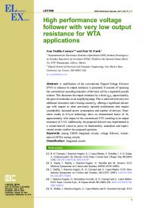
Fig. 1. Current Mirror Block Diagram (a) with reference to ground (b) with reference to positive supply
2017 Devices for Integrated Circuit (DevIC), 23-24 March, 2017, Kalyani, India
312
Table 1 A Comparative Analysis of Current Mirror Structures proposed in literature Structure
Advantages
Disadvantages
Cascode Current Mirror [2]
High Output Resistance
Very High Input and Output Voltage
Wilson Current Mirror [5]
Significant increase in output resistance which is attained by adding only one MOS transistor to the simple current mirror Symmetrical structure leading to high dynamic range and less Current Transfer Error Input, output voltages low, Input impedance low and output impedance high
Higher Input and Output Voltage, Asymmetrical biasing, which causes rather large DC matching errors Higher Input and Output Voltages, High Input resistance
Low Input and Output Voltage, High Bandwidth
Low Dynamic range, high input resistance
Low Input, Output Voltages. Low Power Consumption
Poor dynamic range
Modified Wilson Current Mirror [6] Flipped Voltage Follower based Current Mirror (FVFCM) [8]
Self Cascode Current Mirrors for low voltage applications [9] Floating Gate MOS based Current Mirrors for low voltage application [10]
Fig. 2. Flipped Voltage Follower Cell
Poor dynamic range and poor current transfer error
Fig. 3. Small Signal Model of Flipped Voltage Follower Cell And Output Resistance calculation
III. II.
FLIPPED VOLTAGE FOLLOWER
A Flipped Voltage Follower (FVF) is a fundamental cell used for low power and low voltage analog circuits such as Current Mirrors, OTA’s, OPAMP’s etc. Ramirez et al. [12]. Due to limitation in sinking capability of bias current in Common Drain Amplifier and to achieve a small impedance at the output node, a local shunt feedback is used, by connecting a wire between Gate and Drain of the MOSFET, which forms the basis of the FVF Circuit and is shown in Fig. (2) below. As opposed to a traditional voltage follower, the circuit can source a large amount of current, however there is a limitation on its sinking capability as controlled by the biasing current source Ib. The large source capability is because of low impedance at the output node, which is given by Eqn. (1).
=
(1)
The Small Signal Model of the FVF Cell is shown in Fig. (3) below. Eqn. (2) gives the Small Signal Output resistance of the FVF circuit. This low impedance results in less voltage variation for the applied input current range, which is required for maintaining good current copying accuracy. As a result of its low impedance node, it has widely been utilized as of late in designing high performance and low voltage current mirrors.
MODELLING AND ANALYSIS OF PROPOSED FVF BASED CURRENT MIRROR WITH NEW OUTPUT STAGE
The Flipped Voltage Follower based Current Mirror is best one suitable for low voltage Analog and mixed mode applications Ramirez et al. [12]. From Table (1), we see that although the FVF based Current Mirror has many advantages for low voltage applications, its main disadvantage is its poor dynamic range and current transfer accuracy due to its unsymmetrical structure with respect to the input and output current points. To improve this design aspect of the FVF based Current Mirror, we have proposed a new simple output stage. The basic requirement for a current mirror to be considered as a better performing is that it can provide definite copy of current along with a large output impedance. It should also operate at a high frequency with low supply voltage and low input/output voltage requirements Sackinger et al. [3]. The proposed circuit used inverters as amplifiers connected in negative feedback to ensure that very less current transfer error exists. To this section new output stage is included additionally to split the output current component (Iout) from the bias current component (Ib). The actual motivation about this new output stage is splitting output current via another path to increase dynamic range. Figure (4) below shows the architecture and transistor schematic of the proposed FVF based Current Mirror with new output stage. For calculating the input resistance of the proposed current mirror, the small signal model is shown in Fig. (5). Resistance analysis has been done by considering rob resistance also. Applying nodal analysis at node Y,
2017 Devices for Integrated Circuit (DevIC), 23-24 March, 2017, Kalyani, India
+
(
+
−
+ 1) +
=
313
(2)
Applying nodal analysis at node X,
+
−
(
=
+ 1) (3)
By rearranging the above Eqn. (5) we get +(
=
)
(
+ 1)
+
Fig. 6. Small Signal Equivalent of the proposed circuit for output impedance calculations
(4)
Substituting Eqn. (3) in Eqn. (1) +
(
=
+ 1) (7)
= ( (
)
(
)
)
)
(
(
)
(5) ) >> 1, A1 >> 1 & Assuming ( ≈ ( as a cascode Current source simplifies to,
)
>> 1 and Rob , the Eqn. (5)
≈
(6)
The above Eqn. (6) is for input resistance of the proposed current mirror. The small signal model for calculating output resistance is shown in Fig. (6). Applying nodal analysis at node Z,
Simplifying Eqn. (7), (
=
At node Y,
=
At node A,
=−
)(
)
(8) (9) (10)
Applying KVL at the outer loop,
=
(
−
)
−
+
(11)
Substituting Eqn. (9) & Eqn. (10) in Eqn. (11) we get, =
=
+ (
)
(
+ )(
Assuming A1 & A2 >> 1,
)
(
>> 1,
)
≫
(12)
,
>> 1 Eqn. (12) will be simplified as, ≈ Fig. 4. Proposed Current Mirror Transistor Schematic
IV.
(
)
(
)
(13)
SIMULATION AND COMPARATIVE ANALYSIS OF THE PROPOSED CURRENT MIRROR
In order to evaluate the performance of our proposed Current Mirror design, simulations were performed in Cadence Spectre using UMC 180nm model files with level 49 equations. The results obtained were then compared with those of the existing current mirror structures, which shows the superiority of our proposed current mirror design. Figures (7)-(9) shows the simulation results for the designed Flipped Voltage Follower based Current Mirror structure. Fig. 5. Small Signal Model of Proposed Structure for input impedance calculations
2017 Devices for Integrated Circuit (DevIC), 23-24 March, 2017, Kalyani, India
314
Fig. 7. Input Current versus Output Current of the FVF based Current Mirror
The DC analysis of the proposed flipped voltage follower based current mirror is performed which includes the input, output characteristics and input voltage variation with respect to input current of the proposed FVF based current mirror circuit. To perform the respective analysis, the aspect ratio of the MOS transistors and other parameters which have been used are shown in Table (2). The frequency response of the proposed current mirror is shown in Fig. (8). The -3 dB Bandwidth is found out to be around 75MHz, which is quite low as compared to recently reported high performance current mirrors. The reduction in Bandwidth is due to more number of poles in the circuit. Compensation capacitors are also used to ensure stability of the circuit. The transient response of the proposed circuit is shown in Fig. (9) which projects that the circuit has a peak overshoot of 40 to 50%, which can be a major concern. Furthermore, the proposed circuit won’t have the capacity to raise for larger values of input currents as a result of large number of capacitances created by CMOS Inverter in feedback loop.
Fig. 9. Transient Response of the proposed FVF based Current Mirror Table 2 Component Values used in Proposed Structure Parameter
Values used (W/L)
M1, M2
0.75 µm /0.18 µm
M3,M4
1.5 µm /0.18 µm
M5
30 µm /0.18 µm
M6
15 µm /0.18 µm
MP1,MP2
240 nm /0.18 µm
MN1,MN2
200 µm /0.18 µm
Ibias
2 µA
Ibias1
100 µA
RL
0.5KΏ
VDD
1V
Table (3) below presents a comparative analysis of the proposed FVF based current mirror with that of the existing improved current mirrors proposed in literature. From the table it can be seen that the proposed structure exhibits a very high dynamic range of 1 mA, a high output resistance of 3 GΩ and a moderately low output voltage of 178mV. V. CONCLUSION
Fig. 8. Frequency Response of the proposed FVF based Current Mirror
In this paper, a Current Mirror structure using flipped voltage follower cell at the input section and a new output stage is designed. Simulations were performed in Cadence Spectre
2017 Devices for Integrated Circuit (DevIC), 23-24 March, 2017, Kalyani, India
315
Table 3 Comparative Results of Proposed Current Mirror structures with existing literature Parameters
[1]
[2]
[3]
[4]
[5]
[9]
[10]
Proposed
Supply (V)
1.8
3
1
1.2
1.5
0.5
1.2
1
Vin (min)
NA
0.2
0.245
0.3
0.51
0.3
NA
0.175
Vout (min)
.2-.4
0.15
0.17
0.18
NA
0.38
NA
0.177
Rin (Ώ)
0.75
0.01
0.014
240
0.07
1.3
NA
0.65
Rout (Ώ)
200M
10G
3G
20-45K
55.76G
89K
NA
3G
Bandwidth (Hz)
620M
200M
52M
1G
NA
1.4G
NA
75M
Operating/Dyna mic Range
0 to 80 µA
0 to > 200 µA
0 to 550 µA
0 to 800 µA
0 to 500 µA
0 to 500 µA
0 to 700 µA
0 to 1 mA
using UMC 180nm technology files. The proposed design is then compared with other high performance current mirror structures proposed in literature. Based on simulation results and the comparative analysis, it can be observed that the proposed current mirror with flipped voltage follower cell at the input and a new output stage, has a very high dynamic range of 0 to 1 mA which is higher as compared to the other reported design. Additionally the proposed current mirror has less input impedance, high output impedance, moderate input and output voltages. But, the bandwidth of the current mirror is not as high as compared to some of the other structures proposed in literature. However, this can be overcome by the use of composite MOS transistors instead of single MOS Transistors, in designing the current mirror, which can be considered as a future enhancement to this work. ACKNOWLEDGMENT The authors are thankful to the Ministry of Electronics Information Technology (MeitY), Govt. of India for providing necessary grants and EDA Tools for the smooth functioning of the work.
REFERENCES [1]
C. Toumazou, F.J.Lidgey, D.G.Haigh, “Analogue IC Design: The Current Mode Approach,” Stevenge, U.K.: Peregrines Ltd., 1990. [2] P.Gray,P.Hurst, GM.Robert, S. Lewis, “Analysis and design of analog integrated circuits,” Wiley, 2001. [3] E.Sackinger, W.Guggenbuhl, “ A high-swing, high impedance MOS cascade circuit.,” IEEE J. Solid State Circuits, Vol. 25, pp. 289-298, 1990. [4] S.S.Rajput, S.S.Jamuar, “ Low Voltage, Low Power High Performance Current Mirror for Portable Analogue and Mixed Mode Applications,” Proceedings of IEEE—Circuits Devices and Systems, Vol. 148, No.5, pp.273-278, 2001. [5] G.R.Wilson, “ A monolithic junction FET-NPN operational amplifier,” ISSCC Digest Tech. Papers, 1968. [6] R.Gregorian,G.C.Temes, “ Analog MOS integrated circuits for signal processing,” John Wiley & Sons, New York, USA, 1st edn, 1986. [7] T.C.Choi, R.T.Kaneshiro, R.W.Bodersen, P.Gray, W.B.Jett, M.Wilcox, “ High-frequency CMOS switched-capacitor filters for communication application,” IEEE J. Solid-state Circuits, Vol. 18, pp.652-663, 1983. [8] J.Ramirez-Angulo, R.G.Carvajal, A.Torralba, J.Galan, A.P.Vega-Leal, J.Tombs, “ The Flipped Voltage Follower: A useful cell for low-voltage low-power circuit design,” in Proc. Int. Symp. Circuits and Systems, ISCAS, Vol.3, pp.615-618, 2002. [9] J.Dhanoa, N.Prakash, S.S.Rajput, “ Self Cascode Current Mirrors for low voltage analog circuits,” 5th International Conference on Sciences of Electronic, Technologies of Information and Telecommunication (SETIT), Tunisia, 2009. [10] Neha Singh, Richa Srivastava, “ Improved performance in current mirror suitable in low voltage application,” International Journal of Advanced Research in Electronics and Communication Engineering, Vol. 5, No.6, 2016. [11] C. Tzschoppe, U. Jörges, A. Richter, B. Lindner, F. Ellinger, “Theory and design of advanced CMOS current mirrors,” SBMO/IEEE MTT-S International Microwave and Optoelectronics Conference (IMOC), Porto de Galinhas, 2015. [12] J.Ramirez-Angulo, R.C.Gonzalez, A.L.Lopez-Martin, “ Techniques for very low-voltage operation of continuous-time analog CMOS circuits,” IEEE Proceedings of the 17th International Conference on VLSI Design pp.39-43, 2004.