In recent years we introduced a number of enhancements to the spaceâtime techniques we ..... descent speed of 16 ft/s and a length scale of 21.1 ft, is 2.1 Ã 106.
S. Sathe, R. Benney, R. Charles, E. Doucette, J. Miletti, M. Senga, K. Stein, and T.E. Prepared for Computers & Fluids Prepared for Tezduyar, “Fluid–structure interaction modeling of complex parachute designs with the space– Computers & Fluids time finite element techniques”, Computers & Fluids, 36 (2007) 127–135, http://dx.doi.org/10.1016/j.compfluid.2005.07.010
Fluid–Structure Interaction Modeling of Complex Parachute Designs with the Space–Time Finite Element Techniques
S. Sathe1 , R. Benney2 , R. Charles2 , E. Doucette2 , J. Miletti2 , M. Senga1 , K. Stein3 and T.E. Tezduyar1 1
Mechanical Engineering, Rice University – MS 321 6100 Main Street, Houston, Texas 77005, USA
2
U.S. Army Natick Soldier Center Kansas Street, Natick, MA, 10760, USA
3
Department of Physics, Bethel University 3900 Bethel Drive, St. Paul, MN 55112, USA
Key words: Fluid–structure interactions, FSI, Space–time finite elements, Quasi-direct coupling technique, Light structures. Abstract In recent years we introduced a number of enhancements to the space–time techniques we developed for computer modeling of fluid–structure interaction (FSI) problems. These enhancements, which include more sophisticated fluid–structure coupling and improved mesh generation, are enabling us to address more of the computational challenges involved. Our objective here is to demonstrate the robustness of these techniques in FSI modeling of parachutes involving complex designs. As a numerical example, we have selected a conceptual parachute design with geometric complexities resembling those seen in some of the advanced parachute designs proposed and tested in recent times. We describe our FSI modeling techniques and how we compute the descent and glide performance of this conceptual parachute design.
1
S. Sathe, R. Benney, R. Charles, E. Doucette, J. Miletti, M. Senga, K. Stein and T.E. Tezduyar
1
INTRODUCTION
Computer modeling of the fluid–structure interactions (FSI) involved in parachute aerodynamics has always been challenging especially because a parachute is a light structure very sensitive to the unsteadiness of the aerodynamical forces. The FSI modeling techniques we developed to address those challenges are based on a stabilized space–time formulation. We have recently augmented these techniques with a number of enhancements to increase the robustness and scope of our FSI modeling. These enhancements include more sophisticated fluid–structure coupling techniques and improved mesh generation methods. With these enhancements, we are able to address more of the computational challenges involved in parachute FSI modeling. The challenges we can now address include the type of geometric complexities seen in some of the advanced parachute designs proposed and tested. In our FSI modeling we prefer to use an interface-tracking technique. In this category of techniques, as the structure moves and the spatial domain occupied by the fluid changes its shape, the mesh moves to accommodate this shape change and to follow (i.e. “track”) the fluid–structure interface. Moving the fluid mesh to track the interface enables us to control the mesh resolution near that interface and obtain more accurate solutions in such critical flow regions. One of the most well known examples of the interface-tracking techniques is the Arbitrary Lagrangian– Eulerian (ALE) finite element formulation [1]. The interface-tracking technique we use for discretizing the fluid dynamics equations is the Deforming-Spatial-Domain/Stabilized Space–Time (DSD/SST) formulation [2, 3, 4]. The stabilization is based on the Streamline-Upwind/PetrovGalerkin (SUPG) [5, 6] and Pressure-Stabilizing/Petrov-Galerkin (PSPG) [2] formulations. The SUPG formulation prevents numerical instabilities that might be encountered when we have high Reynolds number and strong boundary layers. With the PSPG formulation, we can use, without numerical instabilities, equal-order interpolation functions for velocity and pressure. An earlier version of the pressure stabilization, for Stokes flows, was introduced in [7]. The DSD/SST formulation was originally developed as a general purpose interface-tracking technique for simulation of problems involving moving boundaries or interfaces, whether fluid– solid or fluid–fluid. Updating the mesh is based on moving it for as many time steps as we can and remeshing it only as frequently as we need to. The mesh moving algorithm is essentially based on the one introduced in [8], where the motion of the nodal points is governed by the equations of elasticity. The Jacobian of the transformation from the element domain to the physical domain is dropped in the finite element formulation of the elasticity equations. This is equivalent to dividing the elastic modulus by the element Jacobian and results in an increase in the stiffness of the smaller elements, which are typically placed near the fluid–structure interfaces. Mesh moving techniques with comparable features were later introduced in [9]. The DSD/SST formulation was first applied to FSI problems in [10] for 2D computation of vortex-induced vibrations of a cylinder, and in [11] for 3D computation of flow in a flexible, cantilevered pipe. In our FSI modeling of parachutes, the structural deformation is governed by the momentum equations for membranes and cables. They are solved using a semi-discrete, finite element formulation in a total Lagrangian framework (see [12]). We see no compelling reason to use a space–time formulation for the structural mechanics equations. The earliest applications
2
Prepared for Computers & Fluids
of the DSD/SST formulation to FSI modeling of parachutes were reported in [13, 14, 15, 16, 17, 18, 19, 20]. In modeling of FSI problems with the DSD/SST formulation (or any other interface-tracking technique), at each time step, we need to solve the fully-discretized, coupled fluid and structural mechanics and mesh-moving equations. What technique to use for the solution of these equations should, to some extent, depend on the nature of the application problem. With that in mind, we have developed block-iterative [11, 13, 16], quasi-direct [21, 22, 23], and direct coupling techniques [21, 22, 23]. The block-iterative technique gives us more flexibility in terms of algorithmic modularity and independence of the fluid and structural mechanics solvers and also better parallel efficiency. The quasi-direct and direct coupling techniques give us more robust algorithms for FSI computations where the structure is light. Various aspects of FSI modeling, including the coupling between the equations governing the fluid and structural mechanics and mesh motion, have also been addressed by many other researchers (see [24, 25, 26, 27, 28, 29, 30, 31]) in recent years. Our objective here is to demonstrate how we are addressing the computational challenges involved in FSI modeling of conceptual parachute designs with geometric complexities similar to those seen in some of the recently-proposed parachute designs. When the objective is to be able to quickly respond to the FSI modeling requirements of a newly-proposed parachute system, algorithmic robustness becomes the primary consideration instead of algorithmic modularity or parallel efficiency. In this paper, for FSI modeling of the conceptual parachute design we are targeting, we employ the quasi-direct coupling technique. The governing equations are reviewed in Section 2. The finite element formulations are given in Section 3. In Section 4, we describe the modeling setup for the conceptual parachute design and present the computed results, including the descent and glide performance. We end with concluding remarks in Section 5.
2 2.1
GOVERNING EQUATIONS Fluid mechanics
Let Ωt ⊂ IRnsd be the spatial domain with boundary Γt at time t ∈ (0, T ). The subscript t indicates the time-dependence of the domain. The Navier–Stokes equations of incompressible flows are written on Ωt and ∀t ∈ (0, T ) as � � ∂u + u · ∇u − f − ∇ · σ = 0 , (1) ρ ∂t ∇·u = 0 , (2) where ρ, u and f are the density, velocity and the external force, respectively. The stress tensor � T ∇u) + (∇ ∇u) /2. Here p is the pressure, σ is defined as σ (p, u) = −pI + 2µεε(u), with ε(u) = (∇ I is the identity tensor, µ = ρν is the viscosity, ν is the kinematic viscosity, and ε(u) is the strain-rate tensor. The essential and natural boundary conditions for Eq. (1) are represented as
3
S. Sathe, R. Benney, R. Charles, E. Doucette, J. Miletti, M. Senga, K. Stein and T.E. Tezduyar
u = g on (Γt )g and n · σ = h on (Γt )h , where (Γt )g and (Γt )h are complementary subsets of the boundary Γt , n is the unit normal vector, and g and h are given functions. A divergence-free velocity field u0 (x) is specified as the initial condition. 2.2
Structural mechanics
Let Ωst ⊂ IRnxd be the spatial domain with boundary Γst , where nxd = 2 for membranes and nxd = 1 for cables. The parts of Γst corresponding to the essential and natural boundary conditions are represented by (Γst )g and (Γst )h . The superscript “s” indicates the structure. The equations of motion are written as � � 2 dy s s d y (3) +η − f − ∇ · σs = 0 , ρ dt2 dt where ρs , y, f s and σ s are the material density, structural displacement, external force and the Cauchy stress tensor [32, 33], respectively. Here η is the mass-proportional damping coefficient. The damping provides additional stability and can be used where time-accuracy is not required, such as in determining the deformed shape of the structure for specified fluid mechanics forces acting on it. The stresses are expressed in terms of the 2nd Piola–Kirchoff stress tensor S, which is related to the Cauchy stress tensor through a kinematic transformation. Under the assumption of large displacements and rotations, small strains, and no material damping, the membranes and cables are treated as Hookean materials with linear elastic properties. For membranes, under the assumption of plane stress, S becomes (see [12]): h � i� ij kl il jk ik jl ij ¯ S = λm G G + µ m G G + G G Ekl , (4) ¯ m = 2λm µm /(λm + 2µm ). Here, Ekl are the comwhere for the case of isotropic plane stress λ ponents of the Cauchy–Green strain tensor, Gij are the components of the contravariant metric tensor in the original configuration, and λm and µm are the Lam´e constants. For cables, under the assumption of uniaxial tension, S becomes S 11 = Ec G11 G11 E11 , where Ec is the Young’s modulus for the cable.
3 3.1
FINITE ELEMENT FORMULATIONS DSD/SST formulation of fluid mechanics
The DSD/SST formulation [2, 3, 4], which was originally based on a Galerkin/least-squares method, is written over a sequence of N space–time slabs Qn , where Qn is the slice of the space–time domain between the time levels tn and tn+1 . At each time step, the integrations are performed over Qn . The space–time finite element interpolation functions are continuous within a space–time slab, but discontinuous from one space–time slab to another. The notation (·)− n and (·)+ n denotes the function values at tn as approached from below and above. Each Qn is decomposed into elements Qen , where e = 1, 2, . . . , (nel )n . The subscript n used with nel is for the general case in which the number of space–time elements may change from one space–time slab
4
Prepared for Computers & Fluids
to another. The essential and natural boundary conditions are imposed over (Pn )g and (Pn )h , the complementary subsets of the lateral boundary of the space–time slab. The finite element trial function spaces (Suh )n� for velocity and (Sph )n for pressure, and the test function spaces (Vuh )n and (Vph )n = (Sph )n are defined by using, over Qn , first-order polynomials in space and time. The version of the DSD/SST formulation introduced in [34] is based on SUPG/PSPG h h h h stabilization and can be written as follows: given (uh )− n , find u ∈ (Su )n and p ∈ (Sp )n such that ∀wh ∈ (Vuh )n and ∀q h ∈ (Vph )n : � Z ∂uh h h h dQ + + u · ∇u − f ε(wh ) : σ (ph , uh )dQ w ·ρ ∂t Qn Qn Z Z Z � � h + h − (wh )+ · ρ (u ) − (u ) q h∇ · uh dQ + wh · hh dP + − n n n dΩ Z
h
�
(Pn )h
+
(nel )n Z
X
Qen
X
Qen
e=1
+
(nel )n Z e=1
Ωn
Qn
� � � � h i 1 ∂wh h h h ∇ ∇ + u · w + τPSPG q · L(ph , uh ) − ρf h dQ τSUPG ρ ρ ∂t ∇ · uh dQ = 0 , νLSIC∇ · wh ρ∇
(5)
where h
h
L(q , w ) = ρ
�
� ∂wh h h + u · ∇ w − ∇ · σ (q h , wh ) . ∂t
(6)
Here τSUPG , τPSPG and νLSIC are the SUPG, PSPG and LSIC (least-squares on incompressibility constraint) stabilization parameters. This formulation is applied to all space–time slabs Q0 , Q1 , Q2 , . . . , QN −1 , starting with (uh )− 0 = u0 . There are various ways of defining the stabilization parameters. The definitions given in [34] are used in the computations reported in this paper:
τSUPG = τSUGN12
hRGN
�
1
+
�− 1
1
2
, 2 2 τSUGN12 τSUGN3 !−1 nen X ∂Na h2RGN h , τ = + u · ∇ N , = SUGN3 a ∂t 4ν a=1 !−1 nen X ∇kuh k , r= = 2 |r · ∇Na | , k ∇kuh k k
(7) (8)
(9)
a=1
τPSPG = τSUPG ,
h 2
νLSIC = τSUPG ku k .
(10) (11)
For more ways of calculating τSUPG , τPSPG and νLSIC, see [35, 34, 36].
5
S. Sathe, R. Benney, R. Charles, E. Doucette, J. Miletti, M. Senga, K. Stein and T.E. Tezduyar
3.2
Semi-discrete formulation and time-integration of structural mechanics
With yh and wh coming from appropriately defined trial and test function spaces, respectively, the semi-discrete finite element formulation of the structural mechanics equations are written as Z
h
w ·
Ωs0
d2 yh ρs 2 dΩs dt
+
Z
s dy
h
w · ηρ Ωs0
h
dt
s
dΩ +
Z
h
h
s
δE : S dΩ =
Ωs0
Z
Ωst
� � wh · th + ρs f s dΩs . (12)
The fluid mechanics forces acting on the structure are represented by vector th . This term is geometrically nonlinear and thus increases the overall nonlinearity of the formulation. The left-hand-side terms of Eq. (12) are referred to in the original configuration and the right-handside terms in the deformed configuration at time t. From this formulation, at each time step, we obtain a nonlinear system of equations. In solving that nonlinear system with an iterative method, we use the following incremental form: � � (1 − α) γC M + + (1 − α) K ∆di = Ri , (13) β∆t2 β∆t where C = ηM. Here M is the mass matrix, K is the consistent tangent stiffness matrix associated with the internal elastic forces, C is a damping matrix, Ri is the residual vector at the ith iteration, and ∆di is the ith increment in the nodal displacements vector d. The damping matrix C is used only in stand-alone structural mechanics computations with specified fluid mechanics forces, while establishing a starting shape for the FSI computations. In Eq. (13), all of the terms known from the previous iteration are collected into the residual vector Ri . The parameters α, β, γ are part of the Hilber–Hughes–Taylor [37] time-integration scheme used here. 3.3
Quasi-direct coupling
The formulation for the quasi-direct coupling approach [21, 22, 23] is written as follows: � Z Z ∂uh h h h h h h dQ + + u · ∇u − f ε(w1E ) : σ (p , u )dQ − w1hE · hh1E dP ·ρ ∂t Qn (Pn )h Qn Z Z � � h h h + h − + q1E∇ · u dQ + (w1hE )+ n · ρ (u )n − (u )n dΩ Z
w1hE
�
Ωn
Qn
+
(nel )n Z
X
Qen
X
Qen
e=1
+
(nel )n Z e=1
Z
� � � � h i ∂w1hE 1 + uh · ∇w1hE + τPSPG∇q1hE · L(ph , uh ) − ρf h dQ τSUPG ρ ρ ∂t ∇ · uh dQ = 0 , νLSIC ∇ · w1hE ρ∇
(nel )n Qn
q1hI∇ · uh dQ
+
X Z e=1
Qen
(14)
i h i 1h τPSPG∇q1hI · L(ph , uh ) − ρf h dQ = 0 , ρ 6
(15)
Prepared for Computers & Fluids
Z
Γ1I
Z
Qn
(w1hI )− n+1
−
Z
+
(nel )n Z
(Pn )h
(16)
� Z ∂uh h h h h h dQ + + u · ∇u − f ε((w1hI )− n+1 ) : σ (p , u )dQ ∂t Qn
h (w1hI )− n+1 · h1I dP
X
Qen
X
Qen
e=1
+
·ρ
�
� � h − h (w1hI )− · (u ) − u 1I n+1 2I dΓ = 0 , n+1
(nel )n Z e=1
" 1 τSUPG ρ ρ
∂(w1hI )− n+1 + uh · ∇(w1hI )− n+1 ∂t
!#
h i · L(ph , uh ) − ρf h dQ
∇ · uh dQ = 0 , νLSIC∇ · (w1hI )− n+1 ρ∇
(17)
Z Z dyh d2 yh h dΩ + w2 · ηρ2 δEh : Sh dΩ · ρ2 2 dΩ + dt dt (Ω2 )0 (Ω2 )0 (Ω2 )0 Z Z Z w2hI · hh1I dΩ . w2hE · hh2E dΩ − w2h · ρ2 f2h dΩ + = Z
Ω2
w2h
(18)
Ω2I
Ω2E
The notation used here is slightly different from that used in Eqs. (5) and (12). Here, subscripts 1 and 2 are used for fluid and structure respectively, and I and E indicate the “interface” and “elsewhere in the domain”, respectively. The traction force is denoted by h. In this formulation, h (uh1I )− n+1 and h1I (the fluid velocity and stress at the interface) are treated as separate unknowns, and Eqs. (16) and (17) can be seen as equations corresponding to these two unknowns, respectively. The structural displacement rate at the interface, uh2I , is derived from yh . This formulation allows for cases where the fluid and structure meshes at the interface are not identical. If they are identical, the same formulation can still be used, but one can also use its reduced version where Eq. (16) is no longer needed and hh1I is no longer treated as a separate unknown. Remark 1: Full discretizations of the quasi-direct formulation described by Eqs. (14)-(18) lead to coupled nonlinear equation systems that need to be solved at every time step. These coupled nonlinear equation systems can be written as follows: N1 (d1 , d2 ) = F1 ,
(19)
N2 (d1 , d2 ) = F2 ,
(20)
where subscripts 1 and 2, again, denote the fluid and structure, respectively. Solution of these equations with the Newton–Raphson method would necessitate at every Newton–Raphson step solution of the following linear equation system: A11 x1 + A12 x2 = b1 ,
(21)
A21 x1 + A22 x2 = b2 ,
(22)
7
S. Sathe, R. Benney, R. Charles, E. Doucette, J. Miletti, M. Senga, K. Stein and T.E. Tezduyar
where b1 and b2 are the residuals of the nonlinear equations, x1 and x2 are the correction increments for d1 and d2 , and Aβγ = ∂Nβ /∂dγ . Careful inspection of Eq. (17) reveals that we could have convergence difficulties when the stabilization terms, which only contribute to the off-diagonal entries of A, are dominant. In such cases, convergence of the iterative solution can be improved by activating the shortcut technique proposed in [36, 38]. In this technique, to reduce “over-correcting” (i.e. “over-incrementing”) the structural displacements, we increase the mass matrix contribution to A22 . This is achieved without altering b1 or b2 (i.e. F1 − N1 (d1 , d2 ) or F2 − N2 (d1 , d2 )), and therefore when the Newton–Raphson iterations converge, they converge to the solution of the problem with the correct structural mass. Remark 2: A slightly altered version of the formulation given by Eqs. (14)–(18) was introduced in [39] by suppressing the stabilization terms in Eq. (17): � � h Z Z ∂u h h h h h dQ + + u · ∇ u − f ε((w1hI )− · ρ (w1hI )− n+1 ) : σ (p , u )dQ n+1 ∂t Qn Qn Z h − (w1hI )− (23) n+1 · h1I dP = 0 . (Pn )h
Our recent experiences show that this leads to a more robust solution algorithm, and good convergence performance can be achieved without augmenting A22 as described in the earlier remark.
4 4.1
TEST COMPUTATIONS Model setup
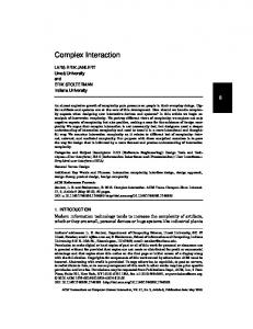
As the test case, we have selected a conceptual parachute design with geometric complexities similar to those seen in some of the advanced parachute designs proposed and tested in recent times. The shape and dimensions of the unstressed parachute are shown in Figure 1. It is in the shape of a cross formed by two bands that are each 46.9 ft long and 21.1 ft wide. The adjacent arms of the “cross” are stitched together along the edges marked with red color in Figure 1. The stitching forms four “vents” with edges marked with blue color. The edges of the skirt, marked with green color, are attached to 28 suspension lines, each 21.0 ft long. The suspension lines connect to 4 risers, each 4.0 ft long. The risers connect to the payload. The parachute is modeled with membranes and cables, and the payload is modeled with a point mass. The membrane stiffness, density, and thickness are set to 2.0 × 10⁵ lb/ft2 , 2.374 slugs/ft3 , and 1.0 × 10⁻⁴ ft, respectively. The cable stiffness, density, and cross-sectional area are set to 1.117 × 10⁷ lb/ft2 , 2.374 slugs/ft3 , and 3.358 × 10⁻⁵ ft2 . For air, as the density and kinematic-viscosity values we use 2.378 × 10⁻³ slugs/ft3 and 1.615 × 10⁻⁴ ft2 /s. The Reynolds number, based on a descent speed of 16 ft/s and a length scale of 21.1 ft, is 2.1 × 10⁶ . The parachute canopy structure is discretized using a finite element mesh with 10,973 nodes and 21,504 elements. A constant air pressure is applied to inflate the parachute to its initial
8
Prepared for Computers & Fluids
2.4 ft
12.9 ft
21.1 ft
20 ft
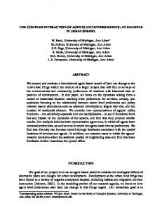
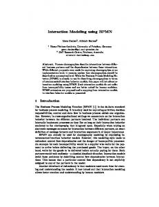
Figure 1: Shape and dimensions of unstressed parachute. The adjacent arms of the “cross” are stitched together along the edges marked with red color. shape, which is determined with a stand-alone structural mechanics computation. The inflationpressure is set to 1.3 times the stagnation pressure, calculated based on the descent speed of 16 ft/s. Figure 2 shows the inflated parachute. To limit the number of unknowns in the fluid mechanics part of the problem, we use a coarser fluid mechanics mesh at the fluid–structure interface. The interface mesh for the fluid has 2,797 nodes and 5,376 elements. Figure 3 shows the fluid and structure meshes at the interface. We note that the quasi-direct coupling approach described in Section 3.3 allows for incompatible fluid and structure meshes at the interface. The volume meshes generated for the fluid typically have approximately 100,000 nodes and 600,000 elements.
4.2
Computation of the descent
In this set of computations we test two different payload weights: 222 lb and 350 lb. We use the quasi-direct coupling approach described by Eqs. (14)–(18). To further improve the convergence of the iterative solution, we activate the shortcut technique described in Section 3.3. In doing that, the mass matrix contribution to A22 increased by a factor 3.0. Both computations were carried out without any remeshing. Figure 4 shows the payload and canopy descent speeds with payload weighing 222 lb and 350 lb. As seen from the plots, the parachute system reaches a near steady descent speed of 15.7 ft/s with payload weighing 222 lb and 18.3 ft/s with payload weighing 350 lb.
9
S. Sathe, R. Benney, R. Charles, E. Doucette, J. Miletti, M. Senga, K. Stein and T.E. Tezduyar
Figure 2: Inflated parachute. 4.3
Computation of the gliding
We compute the gliding performance of the parachute system with the payload weighing 222 lb. We attain gliding in the intended direction (x1 direction) by pulling one of the risers by 2.0 ft and affecting a canopy shape change that generates a force in the x1 direction. The parachute is descending in the x3 direction. The riser is pulled rather quickly, within a period less than 0.3 seconds. In this FSI computation, we use the quasi-direct coupling approach described a by Eqs. (14)–(16), Eq. (23), and Eq. (18). The ∂N ∂t term is dropped from the definition of τSUGN12 given by Eq. (8). For fluid mechanics volume-mesh generation, we use an advanced automatic mesh generator [40] with improved mesh generation capabilities critical to parachute FSI computations. The computation was carried out without any remeshing. Figure 5 shows the payload position along the x1 direction, denoted by the symbol Y1 , as a function of time. We also see, even before the riser is pulled, a glide in an unintended direction (x2 direction). We believe that this unintended glide direction is selected somewhat randomly, very much like what typically happens in a bifurcation problem, from among the possible directions. The payload position along the x2 direction, denoted by the symbol Y2 , is also shown in Figure 5 as a function of time. Figure 6 shows the payload trajectory in the Y1 − Y2 plane. Figure 7 shows the payload velocity, as a function time, in the x1 and x2 directions. We clearly see an increase in the glide velocity in the intended direction after the riser is pulled. Figure 8 shows the flow conditions just before and just after the riser is pulled, as well as at two instants during the subsequent period.
10
Prepared for Computers & Fluids
Figure 3: Fluid (top) and structure (bottom) meshes at the interface.
5
CONCLUDING REMARKS
We have described how we are addressing the computational challenges involved in FSI modeling of conceptual parachute designs with geometric complexities similar to those seen in some of the recently-proposed parachute designs. The core method in our FSI modeling is the DeformingSpatial-Domain/Stabilized Space–Time (DSD/SST) formulation, developed originally for flow problems with moving boundaries and interfaces. A mesh moving method that reduces the need for remeshing is also an important component of our overall computational strategy. In recent
11
S. Sathe, R. Benney, R. Charles, E. Doucette, J. Miletti, M. Senga, K. Stein and T.E. Tezduyar
Descent speed (ft/s)
20
Payload (222 lb) Canopy
19 18 17 16 15 14 0
1
2
Descent speed (ft/s)
20
3 Time (s)
4
5
6
5
6
Payload (350 lb) Canopy
19 18 17 16 15 14 0
1
2
3 Time (s)
4
Figure 4: Payload and canopy descent speeds with payload weighing 222 lb (top) and 350 lb (bottom). years we added a number of enhancements to this computational strategy, including more sophisticated fluid–structure coupling techniques and improved mesh generation. The quasi-direct coupling technique we used for the numerical examples of this paper gives us more algorithmic robustness. This is particularly important for better convergence of the iterative solution process when the structure is light and very sensitive to the unsteadiness of the aerodynamical forces. The improved mesh generation capability is playing an important role in addressing the challenges involved in representing the geometrically complex parachute canopies. As test cases with the conceptual parachute design we considered in this paper, we computed its decent for two different payload weights, as well as its glide, which was induced by pulling one of the risers. In addition to the glide in the intended direction, we also observed, even before the riser was
12
Prepared for Computers & Fluids
40
Y1 Y2
35 30 Y (ft)
25 20 15 10 5 0
Riser pulled
-5 0
2
4
6
8 10 12 Time (s)
14
16
18
Figure 5: Payload position as a function of time. The symbols Y1 and Y2 denote the payload position along the x1 and x2 directions. The intended glide direction is the x1 direction.
35 30
Y2 (ft)
25 20 15 10 Riser pulled
5 0 0
5
10 15 20 25 30 35 Y1 (ft)
Figure 6: Payload trajectory in the Y1 − Y2 plane.
pulled, a glide in an unintended direction. At this time, we believe that this unintended glide direction is selected somewhat randomly from among a set of possible directions. Better understanding of that unintended glide and its interaction with the intended glide will be among the topics we plan to study further in the future. We believe that such “physical explorations” will be more and more within our reach, because we are continuously increasing the robustness and scope of our FSI modeling and we are now able to address more of the computational challenges involved.
13
S. Sathe, R. Benney, R. Charles, E. Doucette, J. Miletti, M. Senga, K. Stein and T.E. Tezduyar
6
V1 V2
5
V (ft/s)
4 3 2 1 0 -1
Riser pulled
-2 0
2
4
6
8 10 12 Time (s)
14
16
18
Figure 7: Payload velocity as a function of time. The symbols V1 and V2 denote the payload velocity in the x1 and x2 directions. The intended glide direction is the x1 direction.
ACKNOWLEDGMENTS This work was supported by the US Army Natick Soldier Center (Contract No. DAAD16-03C-0051), NSF (Grant No. EIA-0116289), and NASA Johnson Space Center (Grant No. NAG91435). We are grateful to Professor Genki Yagawa (Toyo University, Japan) and Mr. Masakazu Inaba for their help in using the advanced automatic mesh generator [40] mentioned in Section 4.3.
References [1] T.J.R Hughes, W.K. Liu, and T.K. Zimmermann, “Lagrangian–Eulerian finite element formulation for incompressible viscous flows”, Computer Methods in Applied Mechanics and Engineering, 29 (1981) 329–349. [2] T.E. Tezduyar, “Stabilized finite element formulations for incompressible flow computations”, Advances in Applied Mechanics, 28 (1992) 1–44. [3] T.E. Tezduyar, M. Behr, and J. Liou, “A new strategy for finite element computations involving moving boundaries and interfaces – the deforming-spatial-domain/space–time procedure: I. The concept and the preliminary numerical tests”, Computer Methods in Applied Mechanics and Engineering, 94 (1992) 339–351. [4] T.E. Tezduyar, M. Behr, S. Mittal, and J. Liou, “A new strategy for finite element computations involving moving boundaries and interfaces – the deforming-spatial-domain/space– time procedure: II. Computation of free-surface flows, two-liquid flows, and flows with drift-
14
Prepared for Computers & Fluids
Figure 8: Flow conditions just before (top-left) and just after (top-right) the riser is pulled, as well as at two instants (bottom-left and bottom-right) during the subsequent period. In each frame, the left, right, and bottom planes show, respectively, the velocity vectors colored with their magnitudes, vorticity, and pressure. ing cylinders”, Computer Methods in Applied Mechanics and Engineering, 94 (1992) 353– 371. [5] T.J.R. Hughes and A.N. Brooks, “A multi-dimensional upwind scheme with no crosswind diffusion”, in T.J.R. Hughes, editor, Finite Element Methods for Convection Dominated Flows, AMD-Vol.34, 19–35, ASME, New York, 1979. [6] A.N. Brooks and T.J.R. Hughes, “Streamline upwind/Petrov-Galerkin formulations for convection dominated flows with particular emphasis on the incompressible Navier-Stokes equations”, Computer Methods in Applied Mechanics and Engineering, 32 (1982) 199–259. [7] T.J.R. Hughes, L.P. Franca, and M. Balestra, “A new finite element formulation for computational fluid dynamics: V. Circumventing the Babuˇska–Brezzi condition: A stable Petrov–
15
S. Sathe, R. Benney, R. Charles, E. Doucette, J. Miletti, M. Senga, K. Stein and T.E. Tezduyar
Galerkin formulation of the Stokes problem accommodating equal-order interpolations”, Computer Methods in Applied Mechanics and Engineering, 59 (1986) 85–99. [8] T.E. Tezduyar, M. Behr, S. Mittal, and A.A. Johnson, “Computation of unsteady incompressible flows with the finite element methods – space–time formulations, iterative strategies and massively parallel implementations”, in New Methods in Transient Analysis, PVP-Vol.246/AMD-Vol.143, ASME, New York, (1992) 7–24. [9] A. Masud and T.J.R. Hughes, “A space–time Galerkin/least-squares finite element formulation of the Navier-Stokes equations for moving domain problems”, Computer Methods in Applied Mechanics and Engineering, 146 (1997) 91–126. [10] S. Mittal and T.E. Tezduyar, “A finite element study of incompressible flows past oscillating cylinders and aerofoils”, International Journal for Numerical Methods in Fluids, 15 (1992) 1073–1118. [11] S. Mittal and T.E. Tezduyar, “Parallel finite element simulation of 3D incompressible flows – Fluid-structure interactions”, International Journal for Numerical Methods in Fluids, 21 (1995) 933–953. [12] M.L. Accorsi, J.W. Leonard, R. Benney, and K. Stein, “Structural modeling of parachute dynamics”, AIAA Journal, 38 (2000) 139–146. [13] K.R. Stein, R.J. Benney, V. Kalro, A.A. Johnson, and T.E. Tezduyar, “Parallel computation of parachute fluid–structure interactions”, in Proceedings of AIAA 14th Aerodynamic Decelerator Systems Technology Conference, AIAA Paper 97-1505, San Francisco, California, (1997). [14] K. Stein, R. Benney, T. Tezduyar, V. Kalro, J. Leonard, and M. Accorsi, “3-d computation of parachute fluid–structure interactions: Performance and control”, in Proceedings of CEAS/AIAA 15th Aerodynamic Decelerator Systems Technology Conference, AIAA Paper 99-1714, Toulouse, France, (1999). [15] K. Stein, R. Benney, T. Tezduyar, V. Kalro, J. Potvin, and T. Bretl, “3-d computation of parachute fluid–structure interactions: Performance and control”, in Proceedings of CEAS/AIAA 15th Aerodynamic Decelerator Systems Technology Conference, AIAA Paper 99-1725, Toulouse, France, (1999). [16] K. Stein, R. Benney, V. Kalro, T.E. Tezduyar, J. Leonard, and M. Accorsi, “Parachute fluid–structure interactions: 3-D Computation”, Computer Methods in Applied Mechanics and Engineering, 190 (2000) 373–386. [17] V. Kalro and T.E. Tezduyar, “A parallel 3D computational method for fluid–structure interactions in parachute systems”, Computer Methods in Applied Mechanics and Engineering, 190 (2000) 321–332.
16
Prepared for Computers & Fluids
[18] K. Stein, R. Benney, T. Tezduyar, and J. Potvin, “Fluid–structure interactions of a cross parachute: Numerical simulation”, Computer Methods in Applied Mechanics and Engineering, 191 (2001) 673–687. [19] T. Tezduyar and Y. Osawa, “The Multi-Domain Method for computation of the aerodynamics of a parachute crossing the far wake of an aircraft”, Computer Methods in Applied Mechanics and Engineering, 191 (2001) 705–716. [20] K.R. Stein, R.J. Benney, T.E. Tezduyar, J.W. Leonard, and M.L. Accorsi, “Fluid–structure interactions of a round parachute: Modeling and simulation techniques”, Journal of Aircraft, 38 (2001) 800–808. [21] T.E. Tezduyar, S. Sathe, R. Keedy, and K. Stein, “Space-time techniques for finite element computation of flows with moving boundaries and interfaces”, in S. Gallegos, I. Herrera, S. Botello, F. Zarate, and G. Ayala, editors, Proceedings of the III International Congress on Numerical Methods in Engineering and Applied Science, CD-ROM, 2004. [22] T.E. Tezduyar, S. Sathe, R. Keedy, and K. Stein, “Space-time finite element techniques for computation of fluid-structure interactions”, to appear in Computer Methods in Applied Mechanics and Engineering, 2005. [23] S. Sathe, Enhanced-Discretization and Solution Techniques in Flow Simulations and Parachute Fluid–Structure Interactions, Ph.D. thesis, Rice University, 2004. [24] R. Ohayon, “Reduced symmetric models for modal analysis of internal structural-acoustic and hydroelastic-sloshing systems”, Computer Methods in Applied Mechanics and Engineering, 190 (2001) 3009–3019. [25] W. Wall, Fluid–Structure Interaction with Stabilized Finite Elements, Ph.D. thesis, University of Stuttgart, 1999. [26] A. Sameh and V. Sarin, “Hybrid parallel linear solvers”, International Journal of Computational Fluid Dynamics, 12 (1999) 213–223. [27] A. Sameh and V. Sarin, “Parallel algorithms for indefinite linear systems”, Parallel Computing, 28 (2002) 285–299. [28] M. Heil, “An efficient solver for the fully coupled solution of large-displacement fluid– structure interaction problems”, Computer Methods in Applied Mechanics and Engineering, 193 (2004) 1–23. [29] B. Hubner, E. Walhorn, and D. Dinkler, “A monolithic approach to fluid–structure interaction using space–time finite elements”, Computer Methods in Applied Mechanics and Engineering, 193 (2004) 2087–2104. [30] W. Dettmer, Finite Element Modeling of Fluid Flow with Moving Free Surfaces and Interfaces Including Fluid–Solid Interaction, Ph.D. thesis, University of Wales Swansea, 2004.
17
S. Sathe, R. Benney, R. Charles, E. Doucette, J. Miletti, M. Senga, K. Stein and T.E. Tezduyar
[31] W. Dettmer and D. Peric, “A computational framework for fluid–rigid body interaction: finite element formulation and applications”, to appear in Computer Methods in Applied Mechanics and Engineering, 2005. [32] A.E. Green and J.E. Adkins, Large Elastic Deformations. Oxford Clarendon Press, Amen House, London, U.K., 1960. [33] A.E. Green and W. Zerna, Theoretical Elasticity. Oxford Clarendon Press, Ely House, London, U.K., 1968. [34] T.E. Tezduyar, “Computation of moving boundaries and interfaces and stabilization parameters”, International Journal for Numerical Methods in Fluids, 43 (2003) 555–575. [35] T.E. Tezduyar and Y. Osawa, “Finite element stabilization parameters computed from element matrices and vectors”, Computer Methods in Applied Mechanics and Engineering, 190 (2000) 411–430. [36] T.E. Tezduyar, “Finite element methods for fluid dynamics with moving boundaries and interfaces”, in E. Stein, R. De Borst, and T.J.R. Hughes, editors, Encyclopedia of Computational Mechanics, Volume 3: Fluids, Chapter 17, John Wiley & Sons, 2004. [37] H.M. Hilber, T.J.R. Hughes, and R.L. Taylor, “Improved numerical dissipation for time integration algorithms in structural dynamics”, Earthquake Engineering and Structural Dynamics, 5 (1977) 283–292. [38] T.E. Tezduyar, “Stabilized finite element methods for computation of flows with moving boundaries and interfaces”, in Lecture Notes on Finite Element Simulation of Flow Problems (Basic - Advanced Course), Japan Society of Computational Engineering and Sciences, Tokyo, Japan, (2003). [39] T.E. Tezduyar, S. Sathe, M. Senga, and K. Stein, “Solution techniques for the fullydiscretized equations in computation of fluid–structure interactions with the space–time formulations”, submitted to Computer Methods in Applied Mechanics and Engineering, 2005. [40] T. Fujisawa, M. Inaba, and G. Yagawa, “Parallel computing of high-speed compressible flows using a node-based finite element method”, International Journal for Numerical Methods in Fluids, 58 (2003) 481–511.
18