... references, such as for motor/servo drive applications as discussed in [7]. .... especially for thyristor-based front-end loads, which require. Authorized licensed ...
IEEE TRANSACTIONS ON INDUSTRY APPLICATIONS, VOL. 32, NO. 3, MAYIJUNE 1996
49 1
Flux-Based Active Filter Controller Subhashish Bhattacharya, Student Member, IEEE, Andre Veltman, 174ember, IEEE, Deepakraj M . Divan, Senior Member, IEEE, and Robert D. Lorenz, Senior Member, IEEE
Abstract- This paper presents a synchronous frame fluxbased control method for a parallel active filter application. The flux-based controller directly implements the inverter switchings in the synchronous reference frame by a hysteresis rule-based carrier-less pulse-width modulation (PWM) strategy to achieve high current bandwidth. This paper addresses the issues and impact on parallel active filtering requirements for utility interface of commonly used harmonic front-ends. The synchronous frame flux-based controller provides additional insights for harmonic current compensation requirements. Simulation results provide the validation of the flux-based active filter controller to meet IEEE Standard 519 recommended harmonic standards for large rated nonlinear loads under balanced and unbalanced supply conditions.
Parallel Active Filter
I. INTRODUCTION
A
CTIVE filtering as a means for harmonic compensation is becoming a cost effective solution for realizing a harmonic free utility interface for large nonlinear power electronic loads such as adjustable speed drives (ASD). Proliferation of power electronics loads, a prerequisite for realizing energy efficiency and productivity benefits, has brought utilities to crossroads. Utilities more frequently encounter harmonic related problems such as substantially higher system losses, required derating of distribution equipment, harmonic interactions between customers or between the utility and load, reduced system stability, and safe operating margins. Utilities are beginning to implement harmonic “standards” such as IEEE Standard 5 19 to alleviate harmonic related problems. It is important to note, however, that IEEE Standard 519 is only applicable at the point of common coupling (PCC) at a plant [ 11. The parallel active filter approach as shown in Fig. 1 is based on the principle of injection of load harmonic currents and hence is characterized by nonsinusoidal current tracking and high current bandwidth requirements [2]-[3]. The achieved harmonic compensation characteristics are dependent on the filtering algorithm employed for the extraction of load current harmonics. It has been shown in [4] and [5] that synchronous frame-based compensators achieve better performance under all supply and load conditions, and without any assumptions on supply voltage ad‘current waveform quality Paper IPCSD 95-77, approved by the Industrial Power Converter Committee of the IEEE Industry Applications Society for presentation at the 1995 IEEE Industry Applications Society Annual Meeting, Lake Buena Vista, FL, October 8-12. Manuscript released for publication November 6, 1995. S. Bhattacharya, D. M. Divan, and R. D. Lorenz are with the Department of Electrical and Computer Engineering, University of Wisconsin, Madison WI 53706-1691 USA. A. Veltman is with the Department of Electrical Engineering, Eindhoven University of Technology, Eindhoven, 5600 MB, The Netherlands. Publisher Item Identifier S 0093-9994(96)02965-9.
Fig. 1. Parallel active filter system diagram.
than state of the art compensators, such as instantaneous reactive power (IRP) or “p-q” theory-based compensators [6] and notch filter-based compensators. Control requirements and implementation issues of parallel active filters are discussed in Section 11. The flux-based controller utilizes the linear relation between the flux and current in a linear inductor and facilitates direct implementation of a current regulator without explicit generation of voltage references. Concept and implementation of the synchronous frame flux-based controller is discussed in Section 111. Experimental measurements and discussion of various commonly used harmonic front-ends and their impact on active filtering requirements are given in Section IV. Sequencing and start-up issues of the parallel active filter are given in Section V. Simulation results for a commonly used utility interface front-end for large rated ASD load is given in Section VI. The flux-based inverter controller achieves implementation of a general current regulator which is well suited for both nonsinusoidal current tracking, such as for active filters, and sinusoidal current references, such as for motor/servo drive applications as discussed in [7].
11. CONTROL REQUIREMENTS FOR PARALLEL ACTIVEFILTERS
The parallel active filter is controlled as a harmonic current source to inject load current harmonics into the supply, and hence the supply line impedance does not influence its compensation characteristics. This requires implementation of a suitable current regulator for the parallel active filter inverter.
0093-9994/96$05.00 0 1996 IEEE
Authorized licensed use limited to: Eindhoven University of Technology. Downloaded on December 10, 2008 at 03:53 from IEEE Xplore. Restrictions apply.
492
IEEE TRANSACTIONS ON INDUSTRY APPLICATIONS, VOL. 32, NO. 3, MAYLJUNE 1996
Complex dy vector-based current regulators-for both carRealization of harmonic free utility interface applications by parallel active filters are in general characterized by the rier and carrier-less modulation schemes-are imperative to alleviate the problems of per phase-based current regulators following: nonsinusoidal multiple frequency current tracking by the [lo]. Their implementation implicitly decouples the phases and hence prevents phase interactions and facilitates prescribed current regulator of the parallel active filter inverter; ability to operate with low inverter output filter induc- adjacent state switching vectors to enable minimization of low frequency current errors and current ripple. tances ( Qziv - Ad) and leading, switch to the active vector which lags the present vector by -60". 3) If the tangential inverter flux error exceeds +A,, switch to the zero vector that involves one switch transition. 4) If the tangential inverter flux error is smaller than -A,, switch back to the same active vector before the zero vector. In this way a tangential inverter flux ripple with constant peak to peak amplitude of &A, is realized, yielding a minimal q-axis inverter current ripple, or an equivalent torque ripple for a machine drive application. The radial inverter flux ripple with an amplitude of ? r a d corresponds to the d-axis inverter current ripple or equivalent magnetizing current ripple for a machine drive application. These rules constrain the inverter flux vector error to a rectangular "box" of dimensions f a d and *Aq in the synchronous deqe frame. For small traclung errors of the inverter flux in both de and qe directions, a square "box" is optimal. For single frequency inverter flux/ current tracking, such as for motor drive applications, the tangential inverter flux/current ripple [18]-[19] has much more impact on the generated torque ripple, thus effectively reducing the simultaneous need for a small radial ripple. The implementation of the flux-based controller in the synchronous de qe frame achieves implicit decoupling of the phases and prevents adverse effects of phase interactions and undesirable limit-cycles in the current. The motivation for carrying out the above inverter switching rules in the synchronous deqe frame as opposed to the stationary d S q Sframe are simple implementation and the fact that the load harmonic current extraction is already performed in the synchronous d"q" frame by the synchronous frame-based controller [4]. The above rule-based hysteresis (or carrier-less) inverter switching strategy implemented in the synchronous deqe frame
Authorized licensed use limited to: Eindhoven University of Technology. Downloaded on December 10, 2008 at 03:53 from IEEE Xplore. Restrictions apply.
BHATTACHARYA et al.: FLUX-BASED ACTIVE FILTER CONTROLLER
495
... ... ... . 1 .
,..
THD=109.6 %; C.F.d.073
0.005 0.01 0.015 0.0% 0.025 0.03 0.035
t -+[SI
I
0.b 0.045
Oh5
(b)
stop (nearest zero vector)
-F*
t
0
JBV
switch +60°
i;d
* EA]
(c)
switch -60
I
.I go ahead (previous active vector) (b) Fig. 4. (a) Principle of switching rules in the synchronous frame and the 8 possible switching states. (b) The four switching rules.
i& * FA] (4
Fig. 5. Case A. (a) Utility interface. (b) Measured line currents by flux controller. (c) In stationary frame. (d) In synchronous frame.
IV. HARMONIC PRODUCING LOADS AND ACTIVEFILTERING REQUIREMENTS
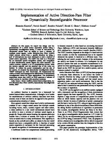
Diode and thyristor bridges constitute common utility interface front-ends. The IEEE Standard 5 19 recommended harmonic standard is a PCC specification and its short circuit ratio (SCR) determines the allowable total harmonic distortion (THD) supply current limits at the PCC. The utility interface characteristics depend on the PCC transformer percentage leakage inductance and on the filtering elements used in the harmonic front-end system. The PCC transformer usually supplies diverse loads in an industrial plant and active filtering solutions should be applied at the PCC in such cases. A simple classification of harmonic performance of various utility interface systems is given below. The experimental waveforms are given for 115 V, 34, 60 Hz system with 25 pH PCC transformer leakage inductance and a dc bus capacitor Cd, = 1340pF. The utility transformer is considered as the PCC, as shown in Figs. 5-8. Implementation issues for parallel active filter system for various commonly used utility interface front-ends are discussed below.
achieves disturbance rejection of dc-link fluctuations, nonsinusoidal voltages on the rectifier input due to commutation, unbalanced supply and load conditions, turn-on and turn-off delays and voltage drops are automatically compensated for, due to the integration of the actual inverter output voltages. This disturbance rejection feature is desirable since it does not require implementation of additional feedforward compensators for disturbance rejection. The flux-based active filter controller is amenable to analogdigital hardware implementation. Hardware implementation of the controller is desirable since it circumvents the sampling and computation delay problems associated with any digital signal processor-based (DSP) implementation, which are the major limitations for high frequency inverter flux/current tracking. Analog controller implementation also effectively alleviates the high-frequency tracking issues A. Diode Reclijier with DC Side Capacitor System related to high-frequency reference change of the inverter Fig. 5(a) shows the most common topology for ASD utility fludcurrent, compared to a sampled current regulator interface front-ends. The supply current i s is discontinuous implementation. with very high peak currents. The supply current THD's are Suppression of the inverter switching frequency ripple by typically around 60% to greater than 130%. The supply peak a capacitive filter and other related issues have not been current, THD and d i / d t significantly increase for stiff ac addressed in this paper. supply systems. Fig. 5(b) shows experimental stationary dSqS
Authorized licensed use limited to: Eindhoven University of Technology. Downloaded on December 10, 2008 at 03:53 from IEEE Xplore. Restrictions apply.
IEEE TR ANSACTIONS ON INDUSTRY APPLICATIONS, VOL. 32, NO. 3, MAYIJUNE 1996
496
the dq stationary frame. The vertices of the hexagon represent whereas, the lines joining two locations of almost constant vertices represent the commutation process from one phase to another in the diode/thyristor rectifier. The distance (from the origin) between the highest and the lowest amplitude is indicated by h in Fig. 6(c). The fundamental component of + this “jumping” supply current vector i i is depicted by the dotted circle in Fig. 6(c). Transformation of the supply current from the stationary dsqs to the’ synchronous deqe frame yields $. as shown in Fig. 6(d). Just after a commutation, the supply current vector reaches the left most point in Fig. 6(d). Since the supply current $ in the stationary d S q S frame is almost constant between commutations, the corresponding supply current vector in the synchronous deqe frame turns in the negative direction (clock-wise) with an angular speed w e t . After the supply current vector has turned by almost 60”, it reaches the right most point, where the next commutation starts. During the commutation period, the supply current vector “jumps” from the right (30” lagging) back to the left (30” leading). Hence the supply current vector $ transitions from one vertex of the hexagon in Fig. 6(c) to the next, and completes one full revolution after six such “jumps” over a fundamental period of the supply frequency. In the synchronous deqe frame these six “jumps” all appear at the same position and this implies that it is sufficient to consider just one 60” sector. The time average+of the supply current vector in the synchronous deqe frame 25 [indicated by I 1 in Fig. 6(d)] represents the fundamental component of the supply current vector $ in the stationary d S q S frame. The vertical size h relates to the supply current amplitude ripple and the width w relates to the angular deviations with respect to the fundamental component as shown in Fig. 6(d). Note that the dc side inductor L d c has the effect of increasing the angular deviation of the supply current vector $ (increase in width w)and reduces the supply current amplitude ripple (decrease in height h). This results in a reduction of the peak harmonic current value and increase in the bandwidth requirement of the active filter for harmonic compensation in order to meet IEEE Standard 519. Note the change in the supply current vectors i i in Figs. 5(d) and 6(d). The supply voltage unbalance effect on the supply current can be compared between Figs. 6(d) and 7(d). The significant decrease in peak supply current value is clearly from a much smaller h-value. The supply current THD depends on the dc side inductor L d c value and the operating point of the load. These front-ends are beset with very high d i / d t problems for stiff ac systems and hence require a high bandwidth active filter for harmonic compensation, particularly in order to meet IEEE Standard 519 higher harmonic limits. The dc side inductor smooths the dc link current, minimizes supply voltage unbalance effects and enables the application of cost-effective parallel active filters, albeit, with the concomitant penalty of high active filter bandwidth requirement. Hence they do not offer an optimal front-end for harmonic compensation if they are required to
&
(a)
THD=28.98 %: C.F.=1.603
20,
I
&
? $-200I
,
,
,
,
,
,
,
,
,
1
0.005 0.01 0.015 0.02 0.025 0.03 0.035 0.04 0.045 0.05
t
--t [SI
6
(b)
s
%
t
6
P
?)2 i&
--t
CAI
(4
(c)
Fig. 6 . Case B. (a) Utility interface. (b) Measured line currents by flux controller. (c) In stationary frame. (d) In synchronous frame.
frame supply current components i2d and waveforms with THD value of 109.6% and crest factor (CF) of 4.0 at 1.1 kW load. Fig. 5(c) shows supply current vector and its extracted fundamental component in the stationary d S q Sframe. Fig. 5(d) shows the supply current vector d’lq; and the affect of supply voltage V, unbalance in the synchronous deqe frame. The markers w.h, and I1 indicate the width (d-component ripple), height (q-component ripple), and fundamental component of the supply current respectively. From Fig. 5(d) it is inferred that harmonic compensation for such diode-capacitor frontends without any ac or dc side filtering elements requires high tangential flux/cun-ent excursions (indicated by h). Hence a cost-effective parallel active filter cannot be implemented for harmonic compensation of such harmonic producing front ends to meet IEEE Standard 519.
&
B. Diode or Thyristor RectiJier with DC Side Inductor System Fig. 6(a) shows another common topology for diode- and thyristor-based ASD utility interface front-ends. In this case the supply current tends to be quasi-square and continuous with THD’s of approximately 3040% and substantially reduced peak values compared to Case A. Fig. 6(b) shows experimental stationary d” qs frame supply current components i& and i;q waveforms with THD of 29% and CF of 1.6 at 1.1 kW load and dc side inductor L d c = 8 mH. The supply current components iid and i i q are the horizontal (real) and vertical (imaginary) component respectively of the supply current + vector i g in the stationary dsq” frame. The supply current vector is shown in Fig. 6(c) and has a hexagonal shape in
&
4
Authorized licensed use limited to: Eindhoven University of Technology. Downloaded on December 10, 2008 at 03:53 from IEEE Xplore. Restrictions apply.
%
BHA'ITACHARYA et al.: FLUX-BASED ACTIVE FILTER CONTROLLER
H
497
vsz
C&$ L
0.005 0.01 0.015 0.02 0.025 0.03 0.035 0.b 0.045 0.b5 t -+ [SI (b)
loEj 5
40
20
0
, -20
0
20
iba + [AI (C)
(d)
(C)
(d)
Fig. 7. Case C. (a) Utility interface. (b) Measured line currents by flux controller. (c) In stationary frame. (d) In synchronous frame.
Fig. 8. Case D. (a) Utility interface. (b) Measured line currents by flux controller. (c) In stationary frame. (d) In synchronous frame.
meet IEEE Standard 5 19. Thyristor front-ends require reactive power compensation depending on their operating point. The flux-based active filter controller can meet reactive power demands with slightly higher active filter rating as explained in Section 111.
dc side inductor Case B as shown in the synchronous deqe frame. AC side line inductors result in significant peak supply current and THD reduction compared to Case A and thus enable the application of cost-effective parallel active filters without the penalty of high bandwidth requirement as required in Case B. However this utility interface front-end has higher cost.
C. AC Supply Side Line Inductor and Diode Rectijkr with DC Side Capacitor System Fig. 7(a) shows a similar utility interface front-end topology to that shown in Case A, but has supply side ac line inductors Ls with the intention of reducing the peak supply current and THD value (typically limited to 40%). Fig. 7(b) shows experimental stationary d" q" frame supply current components i& and i& waveforms with THD of 32.6% and CF of 2.0 at 1.1 kW load and Ls = 1.25 mH. Fig. 7(c) shows supply current vector and its extracted fundamental component in the stationary dsq" frame. Fig. 7(d) shows the supply current vector and the effect of supply voltage unbalance in the synchronous deqe frame. Fig. 7(d) shows that the supply + current vector i;, d-component i;d (w) is significantly reduced compared to Case B, whereas the q-component i'& (h) is increased compared to Case B. Supply-side ac line inductor LS increases the commutation overlap angle, consequently reducing the di/dt and bandwidth requirement of the active filter for harmonic compensation to meet IEEE Standard 5 19 harmonic limits. Note that the ac side inductor LS has the effect 0 : reducing the angular deviation of the supply current vector i; (reduces w) and increases the supply current amplitude ripple (increases h), compared to the
&
D. AC Supply Side Line Inductor, Diode RectiJer with DC Side Inductor, and DC Side Capacitor System Fig. 8(a) shows the most desirable utility interface front-end topology for ASD's and other loads such as dc power supplies. This front-end combines the advantages and eliminates the disadvantages of Cases B and C. Fig. 8(b) shows experimental stationary dSq" frame supply current components i& and i& waveforms with THD of 44% and CF of 2.13 at 3 kW with LS = 125pH and Ldc = 250pH. Fig. 8(c) shows supply current vector and its extracted fundamental component in the stationary dSqSframe and Fig. 8(d) shows the d-axis and qaxis supply current components i& and i>q in the synchronous deqe frame with the effect of supply voltage unbalance, which are slightly higher compared to Fig. 6(d) due to smaller dc ( L d c ) and ac side line inductors ( L s ) used in the laboratory experiment. Supply-side ac line inductors Ls reduce the peak value, THD and the d i / d t of the supply current. The dc side inductor L d c results in continuous supply currents and helps reduce supply voltage unbalance effects on the supply side as can be
%
Authorized licensed use limited to: Eindhoven University of Technology. Downloaded on December 10, 2008 at 03:53 from IEEE Xplore. Restrictions apply.
IEEE TRANSACTIONS ON INDUSTRY APPLICATIONS, VOL. 32, NO. 3, MAYIJUNE 1996
498
seen from Figs. 8(d) and 6(d). This utility interface front-end has the highest cost.
v.
SEQUENCING AND START-UP
The active filter sequencing and protection functions are provided by a sequencer hardware. The active filter sequencer is implemented as a state machine. The start-up process has three states; viz. precharging state, charging state, and compensation state. During the precharging state, the active filter dc bus capacitor Cbus is charged through a diode and resistor to the peak of the supply voltage (650 V). The antiparallel diodes provide a three phase rectifier operation when the active filter contactor is closed. During the charging state, the dc bus PI controller regulates Vbus to its nominal value of 750 V and the harmonic references are isolated by analog switches. This mode allows the lowpass filters of the synchronous frame controller to achieve steady-state values. Harmonic references are enabled during the compensation state. This facilitates a transient-free start-up process. The sequencing and start-up of the active filter is shown in the simulation results in Section VI.
650A
div 650A
div 0
001
5
-9
8
8
003
004
t Fig. 9.
--j
005
0.06
0.07
0.08
[SI
Active filter start-up for 310-kW ASD; balanced supply.
I
-1000
VI. PARALLEL ACTIVEFILTERIMPLEMENTATION FOR ASD LOADS:SIMULATION RESULTS The validation of the flux-based active filter controller is provided by simulation results of a 34, 460-V, 60-Hz, 310-kW ASD load with diode rectifier front-end and a dc side inductor. The PCC transformer percentage leakage inductance is 3.0% ( L s = 50pH) and constitutes the total ac side supply line inductance, which results in a commutation duration of 600 ps at rated load condition. The dc link capacitance is Cd, = 30 mF and the dc side inductor value is L d c = 340kH. The dc side L d c - C d c filter is tuned to 50 Hz. The simulated parallel active filter inverter has a filter inductance of L F = 100 pH, nominal dc bus voltage Vbus = 750 V and dc bus capacitance C,,,, = 10 mF. Figs. 9-1 1 show the simulation results of the active filter operating under balanced supply and load conditions. The supply (and load) current THD of the ASD utility interface front-end is 27% ahd hence, a parallel active filter is viable for such an application. The synchronous dese frame representation of the load current vector in Fig. 10(a) still contains the fundamental component, which is given by the time average + of i;. The harmonic current reference for the active filter is extracted from the load current vector i; by means of synchronous frame-based active filter controller given in Fig. 2, which subtracts the average-low-pass filtered-value of % (representing the fundamental component in the stationary d s q s frame) from the actual itself. This dc removal can be graphically interpreted as moving the load current vector to the origin. During the first 0.04 s as shown in Fig. 9 the dc bus (&us) of the active filter inverter is charged up to 750 V. The active power needed to charge up the dc bus capacitor C,,, of the
002
0
i>i+ [A]
1om
-1000
0
ii + [A]
(a)
9
500
t
0
(b)
-9
1'
800
600
O.
mO.
*
1000
500
- 1000
0
i;
+ [A]
1000
-200
0 i?3d
(C)
200
+ [AI
(4
Fig. 10. Balanced supply. (a) Load current. (b) Supply current before t = 0.04 s. (c) Supply current after t = 0.04 s. (d) Synchronous frame supply current around 0.04 s.
active filter inverter is controlled by the dc bus controller. The dc bus controller generates active filter fundamental current components i$d and i$q in phase with the active filter terminal voltage VF to regulate active power flow. During the charging of the dc bus voltage, supply current vector is very close to + the load current vector ,:z except for the additional switching ripple of the active filter inverter. At t = 0.04 s, the active filter is switched on and provides harmonic compensation of the load current. The active filter reference current components in the stationary d'q' frame ,are given by a& and zgq as shown in Fig. 9. The active filter reference current vector 2; in the synchronous deqe frame is shown in the center of Fig. 10(b). Fig. 10(b)-(c) shows the supply current in the stationary d s q s frame before and after the active filter is started, respectively. Tracking of active filter current reference vector
Authorized licensed use limited to: Eindhoven University of Technology. Downloaded on December 10, 2008 at 03:53 from IEEE Xplore. Restrictions apply.
&
BHATTACHARYA et al.: FLUX-BASED ACTIVE FILTER CONTROLLER
499
XI0-3
1
-10
A*&
0 3 [VS]
Load current: Odb=358 Arms, THD=27.29 %
,
I
Supply current: Odb=361 Arms, THD=1.43%, fsw=8765 Hz
1
do-3
W
Q =-60
Tmin=lO us fsw=8864 Hz I 1 1 1 1 1 1 1 1
I 1 1 1 1 1 1 1 1
I 1 1 1 1 1 1 1 1
I 1 1 1 1 1
0
1
2
4
6
8
1
0
1
2
1
4
f + [kHz1
I-
(b) Fig. 12. Balanced supply, compensation state: load current and supply current frequency spectra.
Fig. 12(a) shows the spectrum of the simulated load current i i . Fig. 12(b) shows that the synchronous deqe frame flux controlled active filter reduces the supply current THD from 27.3-1.4%. The resultant supply current spectrum with this carrier-less flux controller does not show any dominant peaks around the switching frequency of fsw = 8.8 kHz when a T,, = 10 ps is applied. +
10-6
10-5
10-4
At
+ [SI
10-3
10-2
(b)
Fig. 1 1 .
(At,,,
(a) Error flux synchronous frame. (b) Switching time distribution = l o p s , Atmax = 1 9 7 5 ~ s ) .
6
@ in Fig.
A. Unbalanced Supply
10(b) by the actual current vector in Fig. lO(c) is clearly shown in Fig. 10(d), which also shows the supply current vector around the point of transition of switching “ON’ of the active filter inverter. Before the transition,+ the + supply current vector i; follows the load current vector i: in Fig. 10(a). The transition occurs just after the start of a rectifier + commutation. Supply current vector 2; quickly moves to a “steady” position, which is indicated by the “black box” after the active filter is started. Because the supply current vector is slightly lagging the supply voltage vector due to supply side PCC transformer leakage inductance LS , the fundamental + component of the supply current vector i; is displaced to the right of the vertical axis. The synchronous deqe frame in this simulation is attached to the active filter terminal flux
In practice, a balanced supply is an exceptional case and utility supplies usually have small (up to 10%)supply voltage unbalances. The simulation results in Figs. 13 and 14 are given for the same system as for the balanced case, with a supply voltage unbalance of f 5 % in phases A and C, respectively. The effects of such supply voltage unbalance can be seen by comparing the stationary dSqSframe load current component iid in Fig. 13 with the corresponding load current component iid in Fig. 9. Since the synchronous deqe frame controller low pass filters (see Fig. 2) have a cross over frequency of 30 Hz and due to the implementation of a three-legged inverter for the active filter, the supply current is forced to be symmetrical for all three phases, regardless of the unbalance in the supply voltage. This results in a 120-Hz dc bus current ripple which 5$. has to be absorbed by the dc bus capacitor “bus. As a result, Fig. 1l(a) shows that the error flux A62 is constrained to a the ripple voltage on Vbus ini Fig. 13 is much larger compared “box” with size f 1 / 2 . 460 . T,, = 2.3 mVs for T,,, = 10 ps. to that in the balanced case of Fig. 9. However, the ripple The large error on the left indicates the instant when the active voltage on V,,, in Fig. 13 is within acceptable voltage bounds. In Fig. 14(a) the unbalance in the load current vector filter is started at t = 0.04 s. Fig. 10(d) shows the supply in the synchronous deqe frame just before in the stationary dsqs frame is clear from its distorted shape current vector and after this transition. The given dimensions of the “box” compared to that for the balanced supply voltage case as shown Fig. 10(a). The load current in the synchronous deqe frame result in an average switching frequency of f,, = 8.8 kHz. in -+ An important fact is that no pulses shorter than 10 ps occur, 2; shows three distinct orbits instead of just one as for the balanced case in Fig. 10(a>. Fig. 14(b) shows the required as verified from the Fig. 11(b).
G,
Authorized licensed use limited to: Eindhoven University of Technology. Downloaded on December 10, 2008 at 03:53 from IEEE Xplore. Restrictions apply.
&
IEEE TRANSACTIONS ON INDUSTRY APPLICATIONS, VOL. 32, NO. 3, MAYIJUNE 1996
500
unbalanced conditions (in the stationary d S q S frame 355 A peak current versus 285 A peak current for the balanced case). If correction for unbalanced load currents is not required, the cross-over frequency of the low pass filters in the synchronous frame controller as shown in Fig. 2 can be increased from 30 Hz to over 120 Hz. Unbalance can be regarded as a negative sequence of -60 Hz in the stationary dSqS frame, which transforms to -120 Hz in the synchronous deqe frame. Because the 5th and 7th harmonics in the stationary $4' frame (corresponding 360 Hz in the synchronous deqe frame) should not be attenuated by the low pass filters, a higher order low pass filter structure is required.
650A
div 650A
-div
650A
div 650A
div 0
0.01
0.02
0.03
0.04
0.05
006
007
008
t -+ [SI Fig. 13. Active filter start-up for 310-kW ASD; unbalanced supply
t P
-500
0
-1000 iid
-+ [AI
I 1000
I
I ,
-1000
0
ii -+ [A]
-1000
0
i;
1000
(b)
(a)
-+ [A]
0
1000
[AI
i?3d
(c)
(d)
Fig. 14. Unbalanced supply. (a) Load current. (b) Supply current before t = 0.04 s. (c) Supply current after t = 0.04 s. (d) Synchronous frame supply current around 0.04 s.
._ 500
-
The waveform shape of the load harmonic current vector i i highly depends on the rectifier load and the values of dc side capacitors cdcand dc side inductors L d c . Fig. 15 shows how the load current vectors in both the stationary dsqs and synchronous deqe frame depend on the load power operating point (rated 300 kW) without any ac side line inductance ( L s = 0). In practice the dc side C d c - L d c filter resonant frequency is below the supply fundamental frequency. In this case Se = 60 Hz and f f t l t = 1/27r1,/= = 50 Hz. Given this constraint a higher Cdc value will reduce the value of Ldc. However, a higher Cd, value will increase the ripple current and the load current THD, just as a lower load does in Fig. 15. In the simulated case chosen, the rectifier load currents become discontinuous for loads smaller than 0.1 p.u. (10% load rating). As can be seen from Fig. 15, despite the reduction in the load current THD with increasing load, the active filter rating depends on the largest harmonic current peak which happens at rated load. i
0
o
B. Input Harmonics as a Function of Load
600-
400-
200
~
-500 -
0-
CF=3 3
Fig. 15. Supply current waveforms as a function of dc loading. mF, LdL = 340pH.
e
cdc =
30
active filter reference current vector in the stationary d+ S q Sframe for harmonic compensation of load current vector 2;. The compensated supply current THD is 1.64%. Note that slightly larger peak active filter currents result under
VII. CONCLUSIONS This paper demonstrates the validation of the synchronous frame flux-based controller for a parallel active filter application. The synchronous frame flux-based controller implements a hysteresis rule-based carrier-less PWM strategy directly in the complex deqe synchronous frame. This method realizes the full potential of a hysteresis-based current regulator by effectively addressing the limitations of a conventional and other state of the art hysteresis-based current regulators. Direct control of the inverter flux (a continuous variable) enables implementation of the current regulator without explicit generation of voltage references. Simple rules ensure prescribed adjacent state inverter switching vectors and prescribes equal duration zero vectors. This paper emphasizes the need for a systems approach to active filtering. Distinct harmonic compensation requirements and related issues, such as load current THD, peak value of the harmonic current and the required active filter bandwidth, have been identified and addressed for various commonly used utility interface front-ends for ASD loads.
Authorized licensed use limited to: Eindhoven University of Technology. Downloaded on December 10, 2008 at 03:53 from IEEE Xplore. Restrictions apply.
BHATTACHARYA et al.: FLUX-BASED ACTIVE FILTER CONTROLLER
501
It has been shown that for large rated ASD loads, the
-1161 - A. Veltman, P. P. J. van den1 Bosch, and R. J. A. Gorter, “On-line
most desirable utility interface front-end for application of parallel active filters is the diode rectifier front-end with ac and dc side inductors. Transformation of the load current into the synehronous deqe frame directly shows the harmonic compensation required by the parallel active filter in the radial (width w) and tangentia1 (height h) directions. The flux-based regulator tracks the tangential ripple by means of zero of adjacent state vectors and the radial fipple by vectors. The synchronous deqe frame-based controller ensures extraction of harmonic components without any phase shift sensitivity. Simulation results for a utility interface of a large (310 kW) ASD load by a parallel active filter shows compliance with IEEE Standard 519 recommended harmonic standards (THD