Sensors 2012, 12, 9884-9912; doi:10.3390/s120709884 OPEN ACCESS
sensors ISSN 1424-8220 www.mdpi.com/journal/sensors Review
Foot Plantar Pressure Measurement System: A Review Abdul Hadi Abdul Razak 1,2,*, Aladin Zayegh 1, Rezaul K. Begg 3 and Yufridin Wahab 4 1
2 3
4
School of Engineering and Science, Victoria University, Melbourne, VIC 3032, Australia; E-Mail:
[email protected] Faculty of Electrical Engineering, Universiti Teknologi MARA, Shah Alam 40000, Malaysia School of Sport and Exercise Science (SES) and Institute of Sport, Exercise and Active Living (ISEAL), Victoria University, Melbourne, VIC 3032, Australia; E-Mail:
[email protected] Centre for Industrial Collaboration, School of Microelectronic Engineering, Universiti Malaysia Perlis, Arau 02600, Malaysia; E-Mail:
[email protected]
* Author to whom correspondence should be addressed; E-Mail:
[email protected]; Tel.: +61-3-9919-5047; Fax: +61-3-9919-4908. Received: 15 May 2012; in revised form: 27 June 2012 / Accepted: 3 July 2012 / Published: 23 July 2012
Abstract: Foot plantar pressure is the pressure field that acts between the foot and the support surface during everyday locomotor activities. Information derived from such pressure measures is important in gait and posture research for diagnosing lower limb problems, footwear design, sport biomechanics, injury prevention and other applications. This paper reviews foot plantar sensors characteristics as reported in the literature in addition to foot plantar pressure measurement systems applied to a variety of research problems. Strengths and limitations of current systems are discussed and a wireless foot plantar pressure system is proposed suitable for measuring high pressure distributions under the foot with high accuracy and reliability. The novel system is based on highly linear pressure sensors with no hysteresis. Keywords: foot plantar pressure; pressure sensor; wireless system
Sensors 2012, 12
9885
1. Introduction The development of miniature, lightweight, and energy efficient circuit solutions for healthcare sensor applications is an increasingly important research focus given the rapid technological advances in healthcare monitoring equipment, microfabrication processes and wireless communication. One area that has attracted considerable attention by researchers in biomedical and sport related applications is the analysis of foot plantar pressure distributions to reveal the interface pressure between the foot plantar surface and the shoe sole. Typical applications are footwear design [1], sports performance analysis and injury prevention [2], improvement in balance control [3], and diagnosing disease [4]. More recently innovative applications have also been made to human identification [5], biometric [6], monitoring posture allocation [7] and rehabilitation support systems [8–10]. Based on this research it is clear that techniques capable of accurately and efficiently measuring foot pressure are crucial to further developments. The plantar pressure systems available on the market or in research laboratories vary in sensor configuration to meet different application requirements. Typically the configuration is one of three types: pressure distribution platforms, imaging technologies with sophisticated image processing software and in-shoe systems. In designing plantar pressure measurement devices the key requirements are spatial resolution, sampling frequency, accuracy, sensitivity and calibration [11]. These requirements will be discussed in detail later. In-shoe foot plantar sensors have paved the way to better efficiency, flexibility, mobility and reduced cost measurement systems. For the system to be mobile and wearable for monitoring activities of daily life, the system should be wireless with low power consumption. Wireless in-shoe foot plantar measurement systems have potential application to data transfer communication systems, miniaturized biomedical sensors and other uses. For compact, low cost devices for short-range wireless applications an on-chip antenna is a practical solution. On-chip antenna implementation is feasible with the assistance of rapid scaling of low cost complementary metal-oxide-semiconductor (CMOS) technology. The feasibility of creating circuits and systems to operate at lower frequency bands and subsequently reducing the antenna size using on-chip antennas has been discussed [12,13]. This review will first summarize the existing methods for measuring foot plantar pressure and the advantages and disadvantages of a range of commercial pressure sensors used in published research. Subsequently, the discussion will introduce a micro-electromechanical (MEMS) pressure sensor that has considerably enhanced performance characteristics. Finally various solutions presented by researchers to measure foot plantar pressure using in-shoe system will be reviewed. The review critically examines the devices used in measuring systems, such as sensors, processing units and wireless transmitters. The paper compares the compactness, power consumption, number of sensors and placements of sensors used in published systems and we propose a new system, the MEMS sensor. The MEMS sensor will interface with a wireless data acquisition (DAQ) unit, which is a full-custom design using CMOS technology. This novel solution will be on a single chip making it highly compact and low in power consumption. The paper is divided into eight sections. Section 2 presents the requirements for plantar pressure measurement systems. The foot plantar pressure measurement environment will be discussed in Section 3. Section 4 will describe the application requirements of foot plantar sensors. Section 5
Sensors 2012, 12
9886
documents the commercial foot plantar pressure measurement sensors in detail. The wireless foot plantar pressure systems will be reviewed in Section 6. Section 7 presents our proposed new approach to recording foot plantar pressure and the system‟s design. Finally, Section 8 discusses the suitability of the proposed system and conclusions. 2. Needs for Plantar Pressure Measurement Feet provide the primary surface of interaction with the environment during locomotion. Thus, it is important to diagnose foot problems at an early stage for injury prevention, risk management and general wellbeing. One approach to measuring foot health, widely used in various applications, is examining foot plantar pressure characteristics. It is, therefore, important that accurate and reliable foot plantar pressure measurement systems are developed. One of the earliest applications of plantar pressure was the evaluation of footwear. Lavery et al. [14] in 1997 determined the effectiveness of therapeutic and athletic shoes with and without viscoelastic insoles using the mean peak plantar pressure as the evaluation parameter. Since then there have been many other studies of foot pressure measurement; for example, Mueller [15] applied plantar pressure to the design of footwear for people without impairments (i.e., the general public). Furthermore, Praet and Louwerens [16] and Queen et al. [17] found that the most effective method for reducing the pressure beneath a neuropathic forefoot is using rocker bottom shoes and claimed the rocker would decrease pressure under the first and fifth ray (metatarsal head). The metatarsal heads are often the site of ulceration in patients with cavovarus deformity. Queen et al. indicated that future shoe design for the prevention of metatarsal stress fractures should be gender specific due to differences in plantar loading between men and women. With regard to applications involving disease diagnosis, many researchers have focused on foot ulceration problems due to diabetes that can result in excessive foot plantar pressures in specific areas under the foot. It is estimated that diabetes mellitus accounts for over $1 billion per year in medical expenses in the United States alone [18]. Diabetes is now considered an epidemic and, according to some reports, the number of affected patients is expected to increase from 171 million in 2000 to 366 million in 2030 [19]. Improvement in balance is considered important both in sports and biomedical applications. Notable applications in sport are soccer balance training [20] and forefoot loading during running [21]. With respect to healthcare, pressure distributions can be related to gait instability in the elderly and other balance impaired individuals and foot plantar pressure information can be used for improving balance in the elderly [22]. Based on the above discussion, it is crucial to devise techniques capable of accurately and efficiently measuring foot pressure. 3. Foot Plantar Pressure Measurement Environments There are a variety of plantar pressure measurement systems but in general they can be classified into one of two types: platform systems and in-shoe systems. 3.1. Platform Systems Platform systems are constructed from a flat, rigid array of pressure sensing elements arranged in a matrix configuration and embedded in the floor to allow normal gait. Platform systems can be used for
Sensors 2012, 12
9887
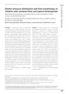
both static and dynamic studies but are generally restricted to research laboratories. One advantage is that a platform is easy to use because it is stationary and flat but has the disadvantage that the patient requires familiarization to ensure natural gait. Furthermore, it is important for the foot to contact the centre of the sensing area for an accurate reading [23]. Limitations include: space, indoor measurement, and patient‟s ability to make contact with the platform, Figures 1 and 2 show a platform-based sensor [24,25]. Figure 1. A platform-based foot plantar pressure sensor emed® by Novel [24].
Figure 2. A platform based foot plantar pressure sensor by Zebris Medical GmbH [25].
3.2. In-Shoe Systems In-shoe sensors are flexible and embedded in the shoe such that measurements reflect the interface between the foot and the shoe. The system is flexible making it portable which allows a wider variety of studies with different gait tasks, footwear designs, and terrains [23]. Figure 3. An in-shoe based foot plantar pressure sensor by Pedar© Novel [24].
Sensors 2012, 12
9888
Figure 4. An in-shoe based foot plantar pressure sensor F-Scan® System by Tekscan [26].
They are, therefore, highly recommended [11,23] for studying orthotics and footwear design but there is the possibility of the sensor slipping. Sensors should be suitably secured to prevent slippage and ensure reliable results. A further limitation is that the spatial resolution of the data is low compared to platform systems due to fewer sensors [11,23]. Figures 3 and 4 illustrate in-shoe based systems [24,26]. 4. Requirement of Foot Plantar Sensors In taking any biomechanical measurements, devices must be optimized for the specific application to ensure that readings are accurate. Detailed analysis must be thoroughly undertaken prior to any measurements and for foot plantar system two main considerations must be met; the target implementation requirements and the sensor requirements. 4.1. Target Implementation Requirements Real-time measurement of natural gait parameters requires that sensors should be mobile, untethered, can be placed in the shoe sole, and can sample effectively in the target environment. The main requirements of such sensors are as follows: (1) Very Mobile: To make a sensor mobile, it must be light and of small overall size [27,28], the suggested shoe mounted device should be 300 g or less. (2) Limited Cabling: A foot plantar system should have limited wiring, wireless is ideal. This is to ensure comfortable, safe and natural gait [28]. (3) Shoe and Sensor Placement: To be located in the shoe sole the sensor must be thin, flexible [29] and light [27]. It is reported that a shoe attachment of mass 300 g or less does not affect gait significantly [27]. Shu et al. [30] mentioned that the sole of foot can be divided into 15 areas: heel (area 1–3), midfoot (area 4–5), metatarsal (area 6–10), and toe (area 11–15), as illustrated in Figure 5. These areas support most of the body weight and are adjusted by the body‟s balance; therefore, ideally the 15 sensors are necessary to cover most of the body weight changes based on the Figure 5 anatomy. (4) Low Cost: The sensor must be affordable for general application [28] to benefit from inexpensive, mass-produced electronics components combined with novel sensor solutions. (5) Low Power Consumption: It should exhibit low power consumption such that energy from a small battery is sufficient for collecting and recording the required data.
Sensors 2012, 12
9889 Figure 5. Foot anatomical areas [30].
4.2. Plantar Pressure Sensor Requirements The key specifications for sensor performance include: linearity, hysteresis, sensing size, pressure range and temperature sensitivity [27,29,31]. Brief discussion of these is important as a basis for the selection of a sensor for specific applications. (1) Hysteresis: Hysteresis can be determined by observing the output signal when the sensor is loaded and unloaded. When the applied pressure is increased by loading or decreased by unloading, two different responses are observed (Figures 6 and 7). Figure 6. Hysteresis caused by loading and unloading a pressure sensor usually measured at the 50% pressure range. Adopted from [32].
F.S.
Sensor Output Midscale Hysteresis
Pressure 50%
100%
Sensors 2012, 12
9890
Figure 7. Negligible hysteresis of MEMS-based pressure sensor [29].
(2) Linearity: The response of the sensor to the applied pressure, when plotted, will show the linearity figure of merit, i.e., how straight the plotted line is. Linearity indicates how simple or complicated the signal processing circuitry will be, a highly linear response requires very simple signal processing circuitry and vice versa, a linear pressure sensor is, therefore, preferred. (3) Temperature Sensitivity: Sensors may produce different pressure readings as the ambient temperature changes. This may be due to the materials that are part of the sensor body as they respond differently to temperature change. A sensor with low temperature sensitivity in the 20 °C to 37 °C range is preferred [29]. (4) Pressure Range: The pressure range is the key specification for a pressure sensor. As different applications require different operating pressures application-specific sensor development is normally adopted in the design. Maximum pressure is the upper limit that the pressure sensor can measure and vice versa. It is also important to note that burst pressure is the maximum pressure that the sensor can withstand before breakage as opposed to maximum pressure. Foot plantar pressure values of up to 1,900 kPa are typically reported in the literature but an extreme pressure of up to 3 MPa has been documented by Urry [31]. One of the foot plantar pressure sensor designs considers 3 MPa as burst pressure value, for comparison when a healthy person of 75 kg body mass is standing on only one forefoot, if pressure is evenly distributed, the interfacial pressure for every 31.2 mm2 foot plantar area approximates 2.3 MPa [33]. (5) Sensing Area of the Sensor: Size and placement of the sensor are also critical, as shown in Figure 8. As a large sensor may underestimate the peak pressure and it is suggested that a minimum sensor of 5 mm × 5 mm should be used, whereas sensors smaller than this must be designed as array sensors. (6) Operating Frequency: It is recommended [31] that to measure foot plantar pressure precisely for running activities the sensors must be capable of sampling at 200 Hz. This frequency is generally considered sufficient for sampling most everyday gait activities. (7) Creep and Repeatability: Creep is the deformation of material under elevated temperature and static stress. It directly relates to the time dependent permanent deformation of materials when
Sensors 2012, 12
9891
subjected to a constant load or stress [34], as in Figure 9. Low creep sensors are one of the key requirements in foot pressure measurement. Repeatability refers to the ability to produce reliable result even after long period of time [29]. High cyclic loads may cause deformation or fatigue [34]. Repeatability problems can be eliminated if the sensor exhibits no creep or deformation over repetitive or high cyclic loads. Figure 8. Effect of sensor sizing and placement. The area of least pressure The best placement of sensor (M)
A wrong placement of sensor
M
The area of maximum pressure
A bigger sensor that may underestimate pressure due to averaging effect
Figure 9. Example of erroneous readings due to sensor creep of Pedar® Insole. The curve is the error reading by the sensor and plotted line is the correct pressure values. Modified from [35].
1400 1300 Total Force (N) 1200 1100
0
1
2
3
Time (hours)
5. Commercial Foot Plantar Pressure Measurement Sensors There are several pressure sensors available on the market. Such sensor technologies utilize capacitive sensors, resistive sensors, piezoelectric sensors and piezoresistive sensors. These sensors provide electrical signal output (either voltage or current) that is proportional to the measured pressure. The required key specifications for a pressure sensor in terms of sensor performance include linearity, hysteresis, temperature sensitivity, sensing size and pressure range. The most common pressure sensors are capacitive sensors, resistive sensors, piezoelectric sensor and piezoresistive sensor.
Sensors 2012, 12
9892
5.1. Capacitive Sensors The sensor consists of two conductive electrically charged plates separated by a dielectric elastic layer. Once a pressure is applied the dielectric elastic layer bends, which shortens the distance between the two plates resulting in a voltage change proportional to the applied pressure [11,31]. Figure 10 shows the capacitive sensor construction. Commercial products based on this system are the emed® platform systems (Novel, Germany) [24] and Pedar® in-shoe systems (Novel, Germany) [24]. Figure 10. Capacitive pressure sensor construction [36].
5.2. Resistive Sensors Force-Sensing Resistor (FSR) is a good example of the resistive sensor. When pressure is applied the sensor measures the resistance of conductive foam between two electrodes. The current through the resistive sensor increases as the conductive layer changes (i.e., decreases resistance) under pressure. FSRs are made of a conductive polymer that changes resistance with force, applying force causes conductive particles to touch increasing the current through the sensors [11,31]. Figure 11 shows the resistive sensor construction and commercial products based on this principle are MatScan® platform systems (Tekscan, USA) [26] and F-Scan® in-shoe systems (Tekscan, USA) [26]. Figure 11. Resistive pressure sensor construction [37].
5.3. Piezoelectric Sensors The sensor produces an electric field (voltage) in response to pressure. Piezoelectric devices have high impedance and therefore susceptible to excessive electrical interference that leads to an unacceptable signal-to-noise ratio.
Sensors 2012, 12
9893
The most suitable material for clinically oriented body pressure measurement is polyvinylidene fluoride (PVDF) because it is flexible, thin and deformable [11,31]. Figure 12 shows the piezoelectric sensor construction. Commercial products based on this system are Measurement Specialties, USA [38] and PCB Piezotronics, Inc., USA [39]. Figure 12. Piezoelectric pressure sensor construction [39]. Applied Pressure
Piezoelectric Element
Electrodes
Output Voltage
5.4. Piezoresistive Sensors This sensor is made of semiconductor material. In Piezoresistive material the bulk resistivity is influenced by the force or pressure applied, when the sensor is unloaded resistivity is high and when force is applied resistance decreases [11]. Figure 13 shows the piezoresistive sensor construction. When there is pressure on the piezoelectric element (quartz crystal) it produces electric charges from its surface. These charges create voltage proportional to the applied force. Commercial products based on this system are FlexiForce® (Tekscan, USA) [26] and ParoTec (Paromed, Germany) [40]. Figure 13. Piezoresistive pressure sensor construction [41].
The requirements of the pressure sensor for the specific application are low hysteresis, linearity of output, and pressure range [27,29,31]. A recommended pressure range for gait analysis (walking) is approximately 1,000 kPa [31] but for sports the pressure range should be larger due to the nature of the movements. There are a number of commercially available foot-pressure sensors on the market but they generally do not fulfil the requirements of many biomechanical applications due to specification and performance limitations. The limitations include but not limited to, the specified hysteresis [29], pressure span and physical sensor dimensions [42].
Sensors 2012, 12
9894
In comparison with traditional foot plantar pressure sensors such as capacitive sensors, resistive sensors, piezoelectric sensors and piezoresistive sensors the MEMS pressure sensors have many advantages. For example, easy communication with electrical elements in semiconductor chips, small size, lower power consumption, low cost, increased reliability and higher precision. To provide a better alternative developments of a specifically designed miniature foot pressure sensor based on MEMS technology have been explored. In response to the needs of such sensors, Wahab et al. [43] successfully designed, fabricated and tested a miniature foot pressure sensor based on MEMS technology that can be inserted in the insole of a shoe [43]. As reported by Wahab et al. [43] significant performance enhancements have been achieved, for example, the sensor is small, has high-pressure range measurement capability, and excellent linearity both at low and high pressures and possesses negligible hysteresis. Currently available in-shoe pressure sensor parameters are compared to Wahab et al. [43] in Table 1. Sensors from Vista Medical, Novel and Tekscan show some performance limitations as they are made of sheets of polymer or elastomer leading to issues such as repeatability, hysteresis, creep and non-linearity of the sensor output [29]. In addition to the above limitations some sensors (e.g., Parotec) have limited pressure range and relatively large dimensions. Figure 14 demonstrates the linearity of the MEMS based pressure sensor and the fabricated sensor as displayed in Figure 15. Table 1. Commercially available in-shoe pressure sensors compared to Wahab et al. sensor. Vista Medical [44] Sensor Size Number of Sensor Range (kPa) Frequency (Hz) Hysteresis
2 mm thick
Tekscan [26]
Novel [24]
0.15 mm thick 1.9 mm thick
Parotec Textile Sensor Wahab et al. [45] [30] [43] 2 ~4 cm Not Specified 2 mm thick (hydrocell)
128 (in shoe)
960 (insole)
99 (insole)
24 (insole)
6 (insole)
15 (insole)
260
1,034
1,200
625
800
3,000
Not Specified
500
Not Specified
250
100
200
Not Specified
24%