516
IEEE TRANSACTIONS ON CONTROL SYSTEMS TECHNOLOGY, VOL. 18, NO. 2, MARCH 2010
A Fractional Order Proportional and Derivative (FOPD) Motion Controller: Tuning Rule and Experiments HongSheng Li, Ying Luo, and YangQuan Chen
Abstract—In recent years, it is remarkable to see the increasing number of studies related to the theory and application of fraccontroller, in tional order controller (FOC), specially many areas of science and engineering. Research activities are focused on developing new analysis and design methods for fractional order controllers as an extension of classical control theory. In this paper, a new tuning method for fractional order proportional and derivative ( ) or FO-PD controller is proposed for a class of typical second-order plants. The tuned FO-PD controller can ensure that the given gain crossover frequency and phase margin are fulfilled, and furthermore, the phase derivative w. r. t. the frequency is zero, i.e., the phase Bode plot is flat at the given gain crossover frequency. Consequently, the closed-loop system is robust to gain variations. The FOC design method proposed in the paper is practical and simple to apply. Simulation and experimental results show that the closed-loop system can achieve favorable dynamic performance and robustness. Index Terms—Fractional calculus, fractional order concontroller, troller (FOC), gain variations, iso-damping, second-order plant.
we may be able to get practical and simple FOC parameters tuning methods for certain specific plants. In this paper, design for typical second-order plant method of fractional order is discussed. Aiming at the specific class of second-order plants, the major contributions of this paper are that the new FO-PD tuning method proposed is simple, practical, systematic, and can achieve favorable dynamic performance as well as robustness. The fractional order proportional and derivative controller FO-PD has the following form of transfer function: (1) . Clearly, this is a specific form of the most where controller which involves an integrator of common , in this paper) and a differentiator of order . order ( The typical second-order plant discussed in this paper is (2)
I. INTRODUCTION
T
HE APPLICATION of fractional order controller (FOC) attracts increasing attention in recent years [1]–[5]. In control practice, it is useful to consider the FOC design for an integer order plant [6]. This is due to the fact that the plant model may have already been obtained as an integer order model in classical sense. In most cases, our objective of using fractional calculus is to apply the FOC to enhance the system control performance. For example, the fractional order controllers are realized by the analogue circuits in [7]; the controller was proposed in [2], where a better control performance was demonstrated in comparison with the classical proportional–integral–differential (PID) controller because of extra real parameters and involved. In general, there is no systematic way for setting the fractional order parameters and presently because of the complexity [6], [8]–[10]. However, Manuscript received May 14, 2008. Manuscript received in final form March 18, 2009. First published June 30, 2009; current version published February 24, 2010. Recommended by Associate Editor F. Chowdhury. The work of Y. Luo was supported by the China Scholarship Council. H. Li is with the Department of Automation Engineering, Nanjing Institute of Technology, Jiangsu 211167, P.R. China (e-mail:
[email protected]). Y. Luo was with the Department of Electrical and Computer Engineering, Utah State University, Logan, UT, 84322, USA. He is now with the Department of Automation Science and Engineering, South China University of Technology, Guangzhou, 510640, China (e-mail:
[email protected]). Y. Chen is with the Electrical and Computer Engineering Department, Utah State University, Logan, UT 84322 USA (e-mail:
[email protected];
[email protected]). Color versions of one or more of the figures in this paper are available online at http://ieeexplore.ieee.org. Digital Object Identifier 10.1109/TCST.2009.2019120
which can approximately model a dc motor position servo system. Note that, the plant gain is normalized to 1 without loss of generality since the proportional factor in the transfer . function (2) can be incorporated in The remaining part of this paper is organized as follows. In design is proSection II, a new tuning method for FOC can enposed for a class of second-order plants. The FOC sure that the given gain crossover frequency and phase margin are achieved and the phase derivative w.r.t. the frequency is zero, i.e., phase Bode plot is flat, at the gain crossover frequency. In Section III, the FO-PD controller design procedures are summarized briefly. Experimental validation are presented in Section IV. Finally, conclusions are presented in Section V. II. FRACTIONAL ORDER PD CONTROLLER DESIGN FOR A CLASS OF SECOND-ORDER PLANTS In this paper, we restrict our attention to a class of seconddescribed by (2). The transfer function of fracorder plants tional order controller has the form of (1). The phase and gain of the plant in frequency domain can be given from (2) by (3) (4) FOC described by (1) can be written as
1063-6536/$26.00 © 2009 IEEE
(5)
LI et al.: FOPD MOTION CONTROLLER: TUNING RULE AND EXPERIMENTS
517
The phase and gain are as follows: (6)
(7) The open-loop transfer function is that and from (3) and (6), the phase of is as follows:
(8) Here, three interesting specifications to be met by the FOC are proposed. From the basic definition of gain crossover frequency and phase margin, we get the following: (i) phase margin specification
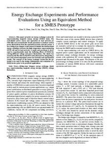
Fig. 1. Dynamometer setup.
that is (10) where
(ii) robustness to variation in the gain of the plant
with the condition that the phase derivative w.r.t. the frequency is zero, i.e., the phase Bode plot is flat, at the gain crossover frequency; it means that the system is more robust to gain changes and the overshoots of the response are almost the same; (iii) gain crossover frequency specification
According to Specification (iii), we can establish an equation about :
(11) Clearly, we can solve (9)–(11) to get , A. For General PD Controller [
.
III. DESIGN PROCEDURES
in (1)]
From (8) and according to Specification (ii):
we arrive at
, and
, and
that means the Specifications (i) and (ii) cannot be satisfied simultaneously for traditional PD controller. B. For Fractional Order Controller According to Specification (i) about the phase of , the and can be established as follows: relationship between
(9) According to Specification (ii) about the robustness to gain variations in the plant, we can establish an equation about in the following form:
It can be observed from (9) and (10) that , can be obtained jointly. Fortunately, a graphical method can be used as a because of the plain practical and simple way to get and fracforms about (9) and (10). The procedures to tune the tional order controller are as follows: 1) given , the gain crossover frequency; , the desired phase margin; 2) given w.r.t , according to (9); 3) plot the curve 1, w.r.t. , according to (10); 4) plot the curve 2, from the intersection point on the 5) obtain the and above two curves; from (11). 6) calculate the IV. EXPERIMENTS A. Introduction of the Experimental Platform A fractional horsepower dynamometer was developed as a general purpose experiment platform [11]. The architecture of the dynamometer control system is shown in Fig. 1. The dynamometer includes the dc motor to be tested, a hysteresis brake for applying torque load to the motor, a load cell to provide force feedback, an optical encoder for position feedback and a tachometer for velocity feedback. The dynamometer was modified to connect to a Quanser MultiQ4 terminal board in order to control the system through MATLAB/Simulink
518
IEEE TRANSACTIONS ON CONTROL SYSTEMS TECHNOLOGY, VOL. 18, NO. 2, MARCH 2010
Real-Time Workshop (RTW)-based software. This terminal board connects with the Quanser MultiQ4 data acquisition card. Then, use the MATLAB/Simulink environment, which uses the WinCon application from Quanser, to communicate with the data acquisition card. Thus complex nonlinear control schemes can be tested since the programmable load can be used to emulate nonlinear relationships. This enables rapid prototyping and experiment capabilities to many nonlinear models of arbitrary form. Without loss of generality, consider the servo control system modeled by (12) (13)
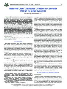
Fig. 2. Dynamometer simulation model. Step position responses with the ITAE optimal proportional controller.
where is the position state, is the velocity, and is the control and are positive coefficients. input, Through simple system identification process, the position control system on the dynamometer and the Quanser MultiQ4 Hardware-in-the-loop can be approximately modeled by a . transfer function B. Experimental Model Simulation Since we already have experimental modeled the position control system with a transfer function , so we can test the simulation effect in Simulink firstly, then the simulation results can be compared with the real-time experiments on the dynamometer. Thus, the verification of our proposed method is more effective. fractional order controller itself is an inActually, the finite dimensional linear filter due to the fractional order differentiator . A band-limit implementation is important in practice. Finite dimensional approximation of the FOC should be utilized in a proper range of frequency of practical interest. The approximation method in this paper is the Oustaloup Recursive Algorithm [12]. Assuming the frequency range to fit is selected . The approximate transfer function of a continuous as with Oustaloup Algorithm is as follows: filter for (14) where the zeros, poles and the gain can be evaluated from
(15) In this experimental model simulation, the frequency range of practical interest is set to be from 1 to 100 Hz for the apcontroller. The gain proximation of the fractional order rad/s , and the desired crossover frequency is set as phase margin is set as . Moreover, the robustness to
Fig. 3. Dynamometer simulation model. Step position responses with controller.
PD
gain variations is required. According to the numerical method , , and in Section III, we can obtain that, . First, the unit step responses are tested to compare the ITAE optimum controller with the FO-PD controller, the ITAE op[13]. In Fig. 2, aptimum parameter is plying the ITAE optimal P controller, the unit step responses are plotted with open-loop gain varying from 1 to 1.5 ( 20% variafractions from the desired value 1.25). In Fig. 3, applying tional order controller, the unit step responses are plotted with open-loop gains varying from 11.088 to 16.632 ( 20% variations from the desired value 13.86). From Figs. 2 and 3, it is obvious that, with the designed controller, faster unit step responses are achieved, the overshoots remain almost constant under gain variations and are much lower than that with the optimal controller, demoncontroller is strating that the controlled system using more robust to gain changes in the loop. Next, the unit ramp responses are tested to compare the ITAE optimum PI controller with the FO-PD controller. The ITAE and optimum PI parameters are designed as [13]. In Fig. 4, applying the ITAE optimal PI controller, the unit ramp responses are plotted with open-loop gain varying from 1.8531 to 3.1837 ( 20% variations from the desired value fractional order controller, the 2.6531). In Fig. 5, applying unit ramp responses are plotted with open-loop gains changing from 11.088 to 16.632 ( 20% variations from the desired value 13.86).
LI et al.: FOPD MOTION CONTROLLER: TUNING RULE AND EXPERIMENTS
519
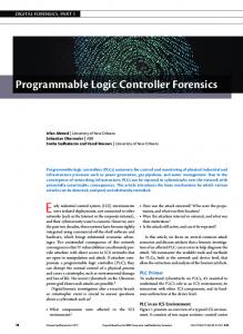
Fig. 7. Dynamometer real-time experiment. Step position responses with P D controller. Fig. 4. Dynamometer simulation model. Ramp position responses with the ITAE optimal PI controller.
Fig. 5. Dynamometer simulation model. Ramp position responses with P D controller.
Fig. 6. Dynamometer real-time experiment. Step position responses with ITAE optimal proportional controller.
It can be seen from Figs. 4 and 5 that the fractional order controller designed by the proposed tuning method is effective. C. Experiments on the Dynamometer Substituting the real dynamometer platform for the DC motor simulation model, the proposed FO-PD controller is tested in a hardware-in-the-loop manner. Figs. 6 and 8 show the ITAE optimal P controller for unit step position responses and the ITAE optimal PI controller for the unit ramp position responses, respectively, Figs. 7 and 9
Fig. 8. Dynamometer real-time experiment. Ramp position responses with ITAE optimal PI controller.
Fig. 9. Dynamometer real-time experiment. Ramp position response with P D controller.
present the fractional order controller designed by the proposed tuning method in this paper for the unit step and ramp position responses, respectively. It is obvious that, with the decontroller, faster responses are achieved and the signed overshoots remain almost constant under gain variations. The overshoots are much lower than those with the ITAE optimal P or PI controllers. V. CONCLUSION In this paper, we have presented a new tuning method for fractional order proportional and derivative controller for a
520
IEEE TRANSACTIONS ON CONTROL SYSTEMS TECHNOLOGY, VOL. 18, NO. 2, MARCH 2010
class of second-order plants. The controller is tuned to ensure that the given gain crossover frequency and the phase margin are achieved and the phase derivative w. r. t. the gain crossover frequency is zero, i.e., the phase Bode plot is flat, at the gain crossover frequency so that the closed-loop system is robust to gain variations and the step/ramp response exhibits an controller tuning method proiso-damping property. The posed in the paper, aiming at typical second-order plant, is practical and simple. Simulation and experimental results show that the closed-loop system can achieve favorable dynamic performance and robustness. ACKNOWLEDGMENT The authors would like to thank the reviewers and the Associate Editor for their useful comments that have improved the presentation of this paper. REFERENCES [1] K. S. Miller and B. Ross, An Introduction to the Fractional Calculus and Fractional Differential Equations. New York: Wiley, 1993. [2] I. Podlubny, “Fractional-order systems and P I D controller,” IEEE Trans. Autom. Control, vol. 44, no. 1, pp. 208–214, Jan. 1999.
[3] B. J. Lurie, “Three-parameter tunable tilt-integral-derivative (TID) controller,” U.S. Patent US5371670, Dec. 6, 1994. [4] A. Oustaloup, X. Moreau, and M. Nouillant, “The CRONE suspension,” Control Eng. Practice, vol. 4, no. 8, pp. 1101–1108, 1996. [5] A. Oustaloup, P. Melchoir, P. Lanusse, C. Cois, and F. Dancla, “The CRONE toolbox for MATLAB,” presented at the 11th IEEE Int. Symp. Comput.-Aided Control Syst. Des., Anchorage, CA, Sep. 2000. [6] D. Xue, C. Zhao, and Y. Q. Chen, “Fractional order PID control of a dc-motor with elatic shaft: A case study,” in Proc. Amer. Control Conf. (ACC), 2006, pp. 3182–3187. [7] I. Podlubny, I. Petras, B. M. Vinagre, P. O’Leary, and L. Dorcak, “Modern control systems,” Analogue Realizations of Fractional-Order Controllers, vol. 29, no. 1–4, pp. 281–296, 2002. [8] J. G. Ziegler and N. B. Nichols, “Optimum settings for automatic controllers,” Trans. ASME, vol. 64, pp. 759–768, 1942. [9] C. A. Monje, B. M. Vinagre, Y. Q. Chen, and V. Feliu, “Proposals for fractional P I D -tuning,” presented at the 1st IFAC Symp. Fractional Differentiation Its Appl. (FDA), Bordeaux, France, 2004. [10] C. Zhao, D. Xue, and Y. Q. Chen, “A fractional order PID tuning algorithm for a class of fractional order plants,” in Proc. ICMA, Niagara, Canada, 2005, pp. 216–221. [11] Y. Tarte, Y. Chen, W. Ren, and K. Moore, “Fractional horsepower dynamometer—A general purpose hardware-in-the-loop real-time simulation platform for nonlinear control research and education,” in Proc. .IEEE Conf. Dec. Control, Dec. 2006, pp. 3912–3917. [12] A. Oustaloup, J. Sabatier, and P. Lanusse, “From fractional robustness to CRONE control,” Fractional Calculus Appl. Anal., vol. 2, no. 1, pp. 1–30, 1999. [13] R. C. Dorf and R. H. Bishop, Modern Control Systems. Upper Saddle River, NJ: Pearson Prentice Hall, 2005, pp. 270–278.