which we have named Omega (Andersen, 1994b; Andersen, 1994a). ..... Andersen, Hans H. K.: âClassification schemes: Supporting articulation work in ...
A ‘contrat sociale’ for CSCW systems: Supporting interoperability of computational coordination mechanisms Kjeld Schmidt, Carla Simone*, Monica Divitini*, Peter Carstensen, and Carsten Sørensen System Analysis Dept. Risø National Laboratory P. O. Box 49 DK-4000 Roskilde, Denmark {kschmidt, phc, carsten}@risoe.dk
*Dept. of Computer Sciences University of Milano Via Comelico, 39/41 I-20135 Milano, Italy {simone, divitini}@hermes.mc.dsi.unimi.it
Working Papers in Cognitive Science and HCI Roskilde University, DK-4000 Roskilde Denmark, 1995 WPCS-95-7
Working Papers in Cognitive Science and HCI Roskilde University DK-4000 Roskilde Denmark, 1995 [WPCS-95-7]
ii
Table of contents Abstract ................................................................................................................... v 1.
Introduction.................................................................................................... 1
2.
Three cases of interoperating coordination mechanisms ............................... 2 2.1. 2.2. 2.3.
The augmented Bill of Materials and its references to common repositories........................................................................ 2 The bug report and the project schedule .......................................... 5 The construction note and the classification scheme....................... 7
3.
The open-ended nature of organizational context ......................................... 9
4.
A general notation for coordination mechanisms ........................................ 11
5.
The interoperability language ...................................................................... 12
6.
Conclusions.................................................................................................. 16
Acknowledgments................................................................................................. 17 References ............................................................................................................. 18
iii
Abstract Evidence from field studies shows that CSCW facilities should be conceived of as specialized devices that must be able to interact with other CSCW facilities in a wider organizational field. Accordingly, it is crucial for a CSCW environment to provide means to ensure that coordination facilities incorporated in different applications can interact. As a solution, a strategy based on a general notation for constructing coordination mechanisms and a multi-agent approach is proposed.
v
1. Introduction In this paper we will show, based on evidence from field studies, that in any given setting multiple CSCW facilities will be used and that it thus is crucial for actors to be able to make the many CSCW facilities interact. First, for the sake of clarity let us introduce a distinction: A CSCW facility can be conceived of as an agglomeration of two specialized component parts: (1) a common data space accessible to multiple actors and (2) a coordination mechanism supporting the different actors in articulating their distributed activities with respect to this common data space. The simplest examples of such coordination mechanisms are, probably, access control mechanisms, floor control mechanisms, and the like. The conceptual structure required for multiple actors to navigate a common repository (e.g., the classification scheme of a data-base or the lattice of links of a hyper-media data-base), can be taken as a coordination mechanism regulating the interactions of multiple actors via this repository (where to put and find what). For multiple distributed actors to be able handle complex interdependencies such as intricate work flows etc., far more elaborate coordination mechanisms are required. Let us, for example, take a collaborative writing application. On one hand, of course, it will provide a common data space in the form of the usual data structures of a conventional word processor: text strings, formatting instructions, document components (paragraphs, sections, headlines, tables, headers, footnotes, etc.). On the other hand, in order to enable multiple actors to act in a concerted manner, the application will probably also provide access and/or floor control mechanisms, facilities for commenting on parts of the document and for creating links between comments, facilities for coordinating the flow of writing and editing the shared document, and so forth. We have called the common data space, as represented by the data structures of the application, the field of work of the cooperative work arrangement at hand; similarly, the coordination mechanism by means of which the actors articulate their distributed activities with respect to this common field of work has been termed the mechanism of interaction. We have developed the requirements for computational mechanisms of interaction elsewhere (Schmidt and Simone, 1995). What we want to do here is to illuminate and explore a crucial problem that so far has not been addressed systematically in CSCW, namely the problem posed by the fact that a given cooperative work arrangement will be working with multiple CSCW applications with different coordination mechanisms and that these are interrelated. The paper will first, based on field studies, demonstrate that multiple coordination mechanisms must be taken to be the norm in any given setting and identify a number of typical modalities of interoperation between mechanisms. Based on this analysis, we propose a strategy based on a general notation for constructing coordination mechanisms and a multi-agent approach.
1
2. Three cases of interoperating coordination mechanisms The evidence presented below has been extracted from findings from field studies that were conducted with a clear focus, namely to identify a number of coordination mechanisms, i.e., coordination protocols supported by symbolic artifacts, computational or paper-based, that serve as means for articulating distributed activities in real-world cooperative settings, in order to understand their inner workings, so to speak. The issue of their interactions on a wider scale were not at the fore. In the course of the field studies, however, instances of interlacing coordination mechanisms were noticed and reported — as a kind of side show to the investigation in focus: the inner workings of coordination mechanisms. Taken together these cases provide a useful starting point for some initial reflections.
2.1. The augmented Bill of Materials and its references to common repositories The first case has been extracted from findings from field studies at Foss Electric (Sørensen et al., 1994; Borstrøm et al., 1995). The company manufactures equipment for measuring quality parameters of agricultural products such as dairy products, grain and meat. The highly complex instruments are primarily sold to laboratories, dairies and slaughterhouses. Projects at Foss Electric involve a varying number of participants, each competent within a specialized area, such as mechanical engineering, electronics, software engineering, optics, chemistry, draughting, process planning, production planning, marketing, quality assurance, quality control, and assembly. The field study concentrated on the System 4000 project which aimed at designing a new instrument for analytical testing of raw milk. The instrument consists of approximately 8,000 mechanical and electronic components, and approximately 200,000 lines of software code. The S4000 project was one of the largest development efforts Foss Electric have undertaken. It involved up to 50 people at any given time and lasted for more than two years. Because Foss Electric produces prototypes as an integrated part of the design process, the designers need to plan and control the production of parts for these prototypes. The S4000 project was characterized by a relatively large number of different mechanical components and involved a large number of project participants. These circumstances led to the invention of an Augmented Bill of Materials (ABOM). The artifact itself is a form printed on a sheet of A4 paper, and a written procedure stipulates the ABOM-form and blue-print flow. A subset of the ABOM is the data on the conventional Bill of Materials (BOM), i.e., a hierarchical structure that describes the breakdown of products into sub-assemblies and parts and gives the identification code of each part type as well as the number of parts required for each part type. Bills of Materials are typically used for production scheduling and control in MRP systems. In addition to the BOM data, the
2
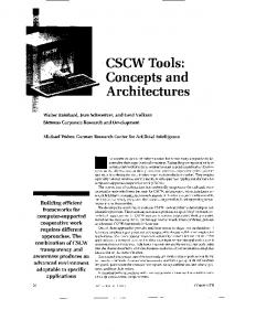
ABOM protocol stipulates who is responsible for which tasks in the production of components for experiments, functional models, and prototypes. Replacing the BOM with the ABOM reduced the need for a weekly coordination meeting. The case of the ABOM illustrates an aspect that can be observed in most if not all coordination mechanisms, namely that the protocol refers to various indices to resources, in this case for example available machining equipment (machines, CAM programs) and surface processes. The ABOM also refers to various roles which are defined and assigned beyond the jurisdiction of this particular protocol. The role definitions are, so to speak, subscribed to. The case also illustrates how one coordination mechanism in its execution interfaces with other coordination mechanisms. For example, let us look at how the ABOM interfaces with the product classification scheme. As an artifact, the product classification scheme is partly paper-based and partly computer supported. The classification of CAD models is normally determined by consulting an A3 size scheme which the draught-person has on the desk. The classification is then entered into the ‘data management system’, i.e., the repository of CAD models, by selecting from a list in a menu on the CAD system. Here, however, all classes and categories in the classification scheme are ordered alphabetically. While the paper-based scheme is a print-out of the classification scheme specified in the database, it is ordered as a tree-structure with classes, categories, sub-categories, and sub-sub-categories. There are 16 classes, and approximately 340 different categories at all levels. As an example, class number 5 is “Hydraulic and pneumatic components”, which has 11 categories. One of these is “Valves”, which has 6 sub-categories and no sub-sub-categories. At the lowest level, each category is specified in the CAD model repository according to a predefined format. Each new component is described in the ABOM, and its CAD model is then classified by means of a look-up in the product classification scheme and by filling in the indexation form. That is, from the point of view of the ABOM coordination mechanism, the ABOM updates the CAD model repository by consulting the product classification scheme and by filling in the CAD model indexation form. The product classification scheme is not, strictly speaking, an index: it does not point to the location of the different models. It is, rather, a nomenclature. This is a reflection the limitations of the available technology. The combination of the product classification scheme, the CAD model indexation form, and the alphabetical index of the data management system of the CAD model repository is, however, an index to the models. In a similar way, the ABOM updates the parts and bill-of-materials indices of the MRP II system with the name of the new model, etc. Thus, as illustrated in Figure #, the ABOM is an integrated part of a system of interlaced coordination mechanisms and information systems (CAD model repositories, inventories, and the MRP II production control system). Also, as pointed
3
out above, the ABOM protocol refers to various indices to resources, in this case for example available pieces of machining equipment (machines, CAM programs) and available surface processes, as well as to various roles which are defined and assigned beyond the scope of this particular protocol. That is, a computational incarnation of the ABOM coordination mechanism would have to be able to: • access the indices to resources; • subscribe to definitions and assignments of organizational roles; • update the CAD model repository by consulting the product classification scheme and by writing to the CAD model indexation form; • update the parts and bills-of-materials indices of the MRP II system with the name of the new model, etc. So far, these observations are hardly shattering revelations. But let us take one more step: Where do these indices come from? The product classification scheme is itself a mechanism emerging from a different — albeit, partly overlapping — cooperative work arrangement to serve specific coordination purposes. The index of the CAD model repository matches this classification scheme but does not represent the hierarchical structure (the product classification scheme is maintained manually because the CAD database does not provide CSCW facilities).
Inventory data base
Public CAD models
COPICS name update CAD model published
OC: Resources
CAD Model Indexation Form
MRP II system (COPICS) Part COPICS name
OC: Roles
CAD model classified
Part number and BOM published
CAD model to be classified
Augmented Bill of Materials
Product Classification Scheme
Figure #. Interactions between the Augmented Bill of Materials (ABOM), the Product Classification Scheme, the Public CAD repository, the MRP II system, and the inventory database. ‘OC’ denotes Organizational Context.
4
The same applies to the indices underlying the MRP II system and the inventory database. They, too, are protocols that are developed and maintained by particular cooperative work arrangements (e.g., production control staff). Because of the nature of the particular technology (conventional database technology assuming an omniscient agent in charge of indexation), this is not immediately apparent but becomes evident on closer inspection. That is, from the point of view of the cooperative work arrangement that uses the ABOM, the organizational context consists of, inter alia, the cooperative work arrangements handling product classification and managing the CAD model repository, the MRP II system, and the inventory.
2.2. The bug report and the project schedule The next case, which describes a set of coordination mechanisms used in software testing, is also taken from the Foss Electric field studies (Borstrøm et al., 1995; Carstensen et al., 1995). The S4000 was the first Foss instrument incorporating an Intel-based 486 PC (as a means of configuring and controlling the operation of the instrument) and its design thus involved a substantial software development task. One of the central activities when developing the software was, of course, the testing of the software. Apart from the software designers, people from four other departments were involved in testing the software, namely service, marketing, and quality assurance and quality control. Now, in the course of the S4000 project, the software designers realized that coordinating, controlling, monitoring, and handling the test activities posed severe problems. In order to handle these problems, a standard paper-based bug report form was devised and implemented together with a set of procedures and conventions for the use of the form. The purpose of this coordination mechanism was to support a decentralized registration and correction of bugs as well as to support a centralized handling and decision making process on how to overcome identified problems. Furthermore, the collection of bug forms was intended to provide an overview of the state of affairs of software testing to testers and designers. The bug report form is a two page form (both sides of one sheet of paper) that all designers and testers involved in testing and developing the software for the S4000 instrument use. It is filled-in, step-by-step, by the tester, the spec-team (three software designers responsible for diagnosing and classifying all reported bugs), and the designer responsible for correcting the bug. Initially, the bug report form can be filled in by anyone involved in testing the software, e.g., software designers, other designers, quality assurance staff, and marketing people. The originator describes and classifies the problem. The spec-team then adds information about affected modules, the designer responsible for the module seemingly causing the bug, the ‘platform integration period’ which specifies the deadline for the correction, and a classification of its perceived severity (as seen from a software reliability perspective).
5
In addition to the bug report mechanism, the software designers introduced and used a number of other artifactually embedded protocols to handle the complexity of coordinating the project. First, a project schedule in the form of a spreadsheet which relates actors, responsibilities, tasks, and deadlines. Second, the directory structure of the software module repository provides a classification scheme for handling software modules and serves the same basic functionality as the product classification scheme discussed in the previous section. In addition to enabling distributed storage and retrieval, the directory structure also provides a set of automated procedures for meshing software modules prior to each integration period. The software testing case has some of the aspects we observed in the engineering design case: • accessing repositories by means of a coordination mechanism serving as an index for external clients, as in the case of the software module repository with the software directory serving as the index. • mechanisms subscribing to roles defined beyond the scope of the immediate cooperative work arrangement. Actors
OC: Roles Bug Report Form
Bug accepted
Project Schedule Tasks
Task announced: correct bug
Modules
P.M.
Task announced: verify bug when corrected
PM identified for verification task
Module published
Module classified Platform Integration Procedure
Software module repository
Software Directory
Figure #. The interacting coordination mechanisms of the software testing case. ‘PM’ denotes the Platform Master, i.e., the actor in charge of the integration of modules and verification of corrections at the end of the current platform period. (‘OC’ denotes the wider organizational context).
The case also demonstrates a more active form of interaction between coordination mechanisms, namely in the form of one mechanism triggering the execution of another coordination mechanism when a certain condition occurs (see Figure #). For example, when a reported bug is accepted as a bug, a new task is announced and entered in the project schedule, i.e., the shift in state of one mechanism (the bug report form) triggers operations on structures in another me-
6
chanism (the spread sheet). Similarly, when a bug is reported to have been corrected, another new task is announced, namely the task of verifying the correction. However, this task is pending until the Platform Master, who will be responsible for the verification, has been appointed and until the point in time where the next integration period is going to start occurs. This starting point is specified in the spread sheet. Another point is worth noticing. Interactions between coordination mechanisms makes it possible for a the instantiation of a mechanism (e.g., a particular bug report sheet) to be incompletely defined; the missing specification can be filled in later by another mechanisms. For example, a platform period number given in the bug report form means not only that the designer has been pointed out as responsible but the platform period number also gives a deadline for the correction task. Moreover, the deadline is not explicitly stated but is inferred from the reference to the platform period and, thus, by a ‘subscription’ to the project schedule spreadsheet where the deadline is stated explicitly. That is, this example indicates that coordination mechanisms can subscribe not only to role definitions but to definitions or specifications of any variable or attribute. Because of this, actors do not necessarily need to specify explicitly what can be inferred from other mechanisms at some point in time.
2.3. The construction note and the classification scheme The last case is based on the findings from the field study of the cooperative production of technical documentation in a large Danish manufacturing company which we have named Omega (Andersen, 1994b; Andersen, 1994a). In engineering design, any change to the specification of product under development has implication for a wide variety of activities within the company. Accordingly, in case of any change to the design, it is mandatory to ensure a systematic notification and distribution of information regarding such changes. In order to handle this dissemination of information, an artifact—the Construction Note—has been introduced. In fact, the estimated number of Construction Notes produced each day in the company exceeds 500 in total. The Construction Note is an is an A4 paper-based form which is used within the company to handle and distribute semi-structured messages and notes regarding product changes and to handle and distribute proposals for product changes. In addition, it is used as a vehicle for delegating responsibilities and tasks and, to a certain degree, for managing inventories, processes, machining tools, and measuring tools. In fact, the Construction Note is the ‘common artifact’ for three different protocols: it can be a ‘proposal for change’, a ‘change note’ or just a message. In this context, we will examine the use of the Construction Note as a change note. The purpose of a change note is to ensure that necessary activities in relation to the change are initiated sufficiently early to be done when the announced change takes effect. It is distributed for any extension, restriction, or change to the speci-
7
fication of quality assurance instructions, bills of materials, raw materials, and drawings (CAD models) of the product in question. In some cases the Construction Note in its change note variant is used in a way that is quite interesting for our purpose, namely as a means of controlling the propagation of changes to another coordination mechanism, the Product Key Classification Scheme. Before we look closer at this, we need to briefly describe this Classification Scheme. The Omega company manufactures in the magnitude of 25,000 different variants of products, distributed over 20 or so product classes. The purpose of the Product Key Classification Scheme is to coordinate the distributed handling of this vast array of different variants on a company-wide scale. More specifically, the Product Key Classification Scheme is used to generate a unique designation for each product type variant. For example, a product key could look like this: UPT D 40-60 X A A AUAE. Each element of the product key refers to pertinent product characteristics. For eaxmple, ‘AUAE’ a the last position denotes that the shaft seal consists of an O-ring, the rotating and stationary components are made of wolfram carbide and coal (made waterproof by using metal), and finally a special type of Teflon is used. All in all, by using this scheme the product variant gets a unique, predictable, and reproducible designation. Now, the Product Key Classification Scheme changes over time, either when a new product family is launched or when new materials and component types are applied. In addition, categories are changed according to changes in products, legislation, standards, etc. When such changes to the scheme are introduced, all relevant actors need to be notified in order for them to take requisite action accordingly. For this purpose, the Change Note protocol is used, for the simple reason that the procedure for disseminating information concerning product changes will ensure that the relevant audience is notified of the changes to the Product Key Classification Scheme for the same product category. That is, one coordination mechanism (the Change Note version of the Construction Note) is used for coordinating the propagation of changes to another coordination mechanism (the Classification Scheme) within a large cooperative work arrangement. One can put it this way: the Construction Note takes the Classification Scheme as its field of work. Of course, in the case discussed here, the execution of the Construction Note mechanism does not change the Classification Scheme, it merely conveys the written instructions to relevant actors so that the recipients may act accordingly. It does however, by executing the underlying dissemination change note protocol for this product category, ensure that the instruction is conveyed to the relevant audience. This limitation, of course, reflects the nature of coordination mechanisms based on inert artifacts such as paper forms. A computational coordination mechanism might execute the changes to the other computational coordination mechanism in an appropriate manner and at an appropriate time and notify the relevant audience that this has happened or will happen.
8
3. The open-ended nature of organizational context We have shown that the different coordination mechanisms (protocols and supporting artifacts) used in everyday cooperative settings intersect and interlace in multiple ways and that they therefore must be made to interoperate. Thus, as CSCW facilities are introduced in different applications and their functionality is enhanced, users will be inundated with overhead activities of making the different mechanisms interoperate: updating each mechanism with respect to changes to other mechanisms. In order to prevent CSCW systems from thereby introducing an impedance between the multitude of interlaced — individual and cooperative — activities, a CSCW environment must provide means for ensuring the interoperability of different coordination mechanisms incorporated in the different applications and systems. In designing CSCW facilities, we therefore need to provide each such facility with an appropriate ‘interface’ to its wider ‘organizational context’ as represented by other CSCW facilities as well as domain-specific information systems such as MIS, OIS, CIM, and CASE systems (De Michelis and Grasso, 1993; Fuchs and Prinz, 1993; Prinz, 1993). The challenge is, as Ellis and Keddara (1994) aptly put it, to make groupware ‘organizationally aware’. Ensuring interoperability among multiple coordination mechanisms is relatively straight-forward if we could assume that the different mechanisms can exchange information via a shared computational representation of organizational context. However, as argued elsewhere (Schmidt, 1994), the organizational context of a cooperative work arrangement is a multi-facetted and open-ended phenomenon. That is, the organizational context can not be defined and bounded in any absolute sense, only relatively, with respect to a particular cooperative work arrangement. The organizational context of a cooperative work arrangement can thus be seen as a ‘field’ of dynamically varying intensity and density, thinning at the edges but seemingly without end: other intersecting arrangements, the enterprise, the division, the corporation, the network of suppliers and other collaborative partners, and customers, unions, banks, shareholders, and so on. This has radical implications for the design of systems supporting the representation of organizational context. We cannot assume that ‘the organization’ is a well bounded, closed, finite entity. What is within and beyond the organizational context is contingent, negotiable. We therefore cannot assume that the representations of organizational context are or can be managed by a single godlike agency. They are, most likely, themselves constructed and maintained cooperatively. Now, since the representations of organizational context cannot be assumed to be defined by a single omniscient agency, it must be assumed that such representations are developed and maintained by multiple agencies, without the all-knowing guidance of a universally shared comprehensive scheme, that is, by relatively autonomous agencies. Accordingly, in the design of CSCW systems supporting awareness of and access
9
to representations of organizational context, we need to address the issue of how such representations can be managed cooperatively in an ongoing process of distributed decision making. The strategy we propose to solve this problem rests on two pillars: On one hand a general notation for constructing coordination mechanisms so that they can be made to interoperate at all, and on the other hand an interoperability language allowing components of multiple coordination mechanisms to interact dynamically. The concept of cooperative work underpinning our approach is that the articulation of cooperative activities should be conceived of as an inherently recursive phenomenon (Gerson and Star, 1986). That is, the articulation of the distributed activities of one cooperative work arrangement with respect to its field of work may itself be handled cooperatively. In other words, one cooperative work arrangement can take the organization of another cooperative work arrangement as its field of work, and vice versa. The recursiveness of articulation work is what makes the open-endedness of the organization of cooperative work manageable.
10
4. A general notation for coordination mechanisms Interoperability of coordination mechanisms (CM) requires that the notation for constructing them meets the following requirements: • all coordination mechanisms must be expressed at the semantic level of articulation work (that is, they must be at the same level of granularity); • CMs must be modular, since interoperability involves all components of the CMs (the one embodied in the CSCW application and the ones embodied in its OC); • it must be able to represent a typology of interactions (awareness, etc.) among these components in order to cover all the interoperability requirements. As for the first point, we are not speaking of interoperability at a low technological level (API, OLE, DDE, etc.). Rather, we want to get interoperability at the level of the involved coordination mechanisms. This is achieved by grounding the notation in a model of articulation work that establishes the granularity and attributes of the objects the notation is dealing with (Schmidt and Simone, 1995). The concepts of the model (Objects of Articulation Work, OAW) are quite standard (role, task, actor, etc.). What is particular is their characterization in terms of their communication capabilities (awareness, coordination, creation, activation, etc.). So, each OAW has associated a set of possible behaviors that are selected and activated when the OAW is referred to by other OAWs or by other (components of the) coordination mechanisms. This distinguishes our approach from existing proposals in the CSCW framework (Bowers et al., 1988; COSMOS, 1989; Johnson, 1992; Kaplan et al., 1992; Malone et al., 1992; Ellis and Keddara, 1994) and from Object Oriented environments for the design of (CSCW) applications (De Champeaux et al., 1993). Secondly, since interoperability involves the objects and their different aggregations into coordination mechanisms, the modularity of the notation is based on the notion of agent, intended as a software component specialized to accomplish specific articulation functions. More specifically, every object of the model is represented by an agent and a CM results in a layered structure of interacting agents among which a basic role is played by the agents representing the artifacts (bug report form, ABOM, etc.) governing the articulation work. Finally, articulation functions are described in terms of an ‘interoperability language’ that allows for the specification of the type of messages the agents exchange in order to accomplish these functions. The model underlying the notation and its multi-agent structure have been described in (Divitini et al., 1995; Simone et al., 1995) as a means for fulfilling another basic requirement of our approach, namely malleability. Malleability means adapting a given CM to the varying needs of the current cooperative work setting. Here, however, we focus on the interoperability language and how it relates to the requirements elicited by the field cases.
11
5. The interoperability language The interoperability language has two basic primitives whose content, the message, takes diferent forms in order to express various interoperbility modes: ! and ?
with the following meaning, respectively: the component in whose specification the communication occurs sends to / receives from the content . is a two-valued parameter: the default value ‘must’ requires an acknowledgment from the receiver, while the value ‘may’ does not. The syntax of the interoperability language accounts for the information needed by its interpreter in order to realize the interoperability and by no means should be considered as a syntax to be directly adopted in the user interface. Using this language, we can define the different modes of interoperability among coordination mechanisms described in the field studies as follows: Awareness mode: The simplest interoperability mode is when a component broadcasts to its environment a notification of the change of its internal state. In this case the message takes the following form: tell (*)1 and the parameter is set to ‘may’. For example, in the case of the bug report mechanism the Bug Report Form (BRF) informs the Tester2 on the evolution of the bugs he reported. This is only a sort of notification that does not impact on the behaviour of the Tester and it appears just in its UserInterface. As another example, a few days after the next platform integration period the PM sends a notification to the designers (RDs) responsible for the corrections in this period. Coordination mode: The symmetric message, namely ask (*), together with the message of the form: perform (read (*) ), are used when the sending CM wants to get information into some variables in order to trigger some subsequent actions. In this case, the requestor is the active CM. On the other hand, the receiver can also be the passive part, i.e., when one mechanism is triggering by enforcing another CM into action by using the previous tell message together with the message of the form: perform (update (*) )3 . In all cases, the parameter is set to ‘must’ and the interoperability is in coordination mode. For example, when the correction is terminated the RD sends to the BRF mechanism an update message containing the related information. The latter will be 1
In the following, the operator * denotes finite sequence of items of sort X.
2
Here and in the following, capital letters denote an actor with that role or a software agent that, to some extent and in some capacity, acts on behalf of the actor.
3
Both in the case of a perform(read(…)) and an ask(…), the sender wants to get the value of the specified variables. The main difference is that in the first case the sender knows about the structure of the data owned by the receiver and therefore the command must terminate successfully; in the second case, the variables denote an information structure owned by the sender where the command deposits the asked values, if and when it terminates successfully. An analogous situation characterizes the differences between perform(update(…)) and tell(…).
12
accessed via a read message by the Platform Master (PM) before starting the verification of the correction. If the correction is not accepted by the PM, the specteam (ST) receives a tell message triggering the fact that the bug must be processed again. This is an example of an ask message. When the spec-team is deciding on the diagnosis of a bug and on who is going to correct it, they need contextual information. For this reason, if needed, they can send an ask to other CMs for various information, like for example, the architecture of the software complex, the relations between software modules and the responsible designer, the workload of different actors, and so on. Reference mode: The third interoperability mode is that of a mechanism subscribing to a policy contained in (a component of) another mechanism. There are different types of subscription. First of all, it is possible to subscribe to a policy contained in the definition of an object of articulation work, typically of a role or a resource. In this case, the message takes the form: perform (activate (, *)). For example, when an actor is assigned to a role, the latter is referenced in order to activate the related policy, for example that the actor must possess a specific skill or its workload must be less than a predefined amount. Secondly, the policy to be subscribed is described by another mechanism. In this case, the message takes the form: perform (activate (, *)). This primitive has the effect of creating and activating the related protocol that possibly interacts with other (components of the current) CMs by means of messages of the type: perform (participate (, *) ). For instance, in the example of the Bug Report mechanisms the Tester can send an activate message to the CM devoted to handle the conversation protocols (Conv-CM) in order to activate a help request. This protocol involves the ST as partner via a performparticipate message. The reference mode allows one to deal with another situation often encountered in the field studies, namely when a CM is accessed and used by actors beyond the cooperative work arrangement that is its proper jurisdiction. This is what the designers at Foss Electric do with the CM which underlies the MRP II system and is handled by the production control staff and the operators in production. In such cases, the CM is used by actors beyond the cooperative work arrangement that constitute its jurisdiction by traversing it as an index to the field of work of that (hidden) cooperative work arrangement. This is the typical case when the referenced mechanism is a classification scheme, the activation of which allows the classification schema to be used as a map to reach the appropriate information in an ‘unknown’ domain. Recursive mode: A fourth mode accounts for the recursive structure of the organizational context when a CM is (dynamically) modified by another CM. In this case the message takes the form: perform (over-write (*, *) ) to enforce modifications on some items (objects and/or components) in the receiving CM. When the first group of parameters takes the value ‘empty’ the command corresponds to the creation of the second group of items. An example of recursiveness can be found in the construction note that serves as a CM for
13
controlling the propagation of changes to the product key classification scheme: in fact, one CM (the Change Note protocol of the Classification Note) takes another CM (the Product Key Classification Scheme) as its field of work. Linking mode: The last interoperability mode refers to the possibility of constructing compound mechanisms from existing ones, that is, by specifying the interface each CM presents to the other linked CMs. The interface establishes which information can be mutually accessed and communicated by the involved CMs. The constituents of the interface are: 1. the access rights to the internal state of the other CMs, namely read and update capabilities, possibly restricted to some specific parts of the internal state; 2. the primitives to express the awareness, coordination, reference, and recursiveness modes of interoperability with the linked CMs; 3. the primitives containing the synchronization message: sy nc h (*, ). This communication, typical of the linking mode, allows the specification of two types of synchronization among the behaviours of the constituent CMs: sequence and concurrency. The interface then monitors the behavior of the CM and manages the additional communication capabilities derived from linking it to the other CMs. The interface can be described as another agent playing the role of ‘receptionist’ proposed in the Actor Model (Agha et al., 1993). Here below, we show the interface of the Bug Report mechanism (BRM), where SW-CM denotes the CM managing the software directory. BRM-Interface= name coordination awareness
linking
reference to referenced by defined by adapted by
BRM ST ? perform (update(STinfo))-> scheduler! tell(new-bug) ST ? perform (update(STinfo))->SW-CM !tell (STinfo) PM?perform(update(correction: OK))->SW-CM!tell ((correction: OK)) Scheduler ? synch((Scheduler...AssignPM, BRM.PM-BRM. (BRF ! perform (read(bug-to-correct))), sequence)) Scheduler ! synch((Scheduler..AllocateResources, BRM.RD-BRM. (correct))), sequence) ConvCM! perform(activate(helpRequest, ST-BRM)) ConvCM>?perform (participate (helpRequest, tester-BRM) * none SW-P.M?over-write (empty, “some items”) SW-P.M ? over-write(BRM, tester, PM, new-BRF, new- tester, new-PM)
The meaning of the various slots are as follows: Coordination: When the ST accepts a bug, the BRM must tell the Scheduler that a new correction must be considered during the planning. Awareness: Moreover when the new bug is accepted, the BRM notifies the SW-CM, so that the latter is aware that a bug has been detected within a specific module. The same happens when the bug is corrected
14
Linking: In the first communication the BRM is passive, in the sense that the PM is suspended until the Scheduler performs ‘AssignPM’. After this task is accomplished, the PM can read in the BRF the new bug to be corrected. In the second one the BRM must require the activation of ‘Allocate Resources’ before ‘correct’ can be performed by the RD. Reference: To express that BRM makes use of the Conv-CM. Recursiveness: The BRM is prepared to receive from the SW-P.M two types of messages: one for its definition and one for its adaptation (In the interface we give only an example of possible modifications).
15
6. Conclusions Based on field study evidence, it is our contention that a crucial problem in the design of CSCW facilities that are acceptable under real world conditions is to ensure that such facilities can interoperate. Given the open-ended nature of organizational context, this is a non-trivial problem. We have suggested a strategy to solve this problem based on, on the one hand, a general notation for constructing coordination mechanisms and, on the other hand, an interoperability language supporting concerted interactions among coordination mechanisms in different interoperation modes. The suggested general notation has been specified formally (in outline) and is currently being implemented in a multi-agent architecture. It goes without saying that the proposed architecture is not a panacea. It provides support for interoperability but the distributed handling of changes to a population of interoperating coordination mechanisms will, of course, require the concomitant development of standard interfaces, programming standards, conventions for good practice. On the other hand, in line with the notion of the recursive nature of articulation work, the distributed handling of changes to a population of interoperating coordination mechanisms can itself be supported by coordination mechanisms for managing changes. And so forth.
16
Acknowledgments The research reported in this paper is supported by the European Union’s ESPRIT Basic Research project COMIC (Action 6225) and by the Danish Research Council for the Natural Sciences. Our thanks are due to our partners in the COMIC project in general and to Wes Sharrock and James Pycock in particular for introducing the notion of bottom-up construction of workflows by means of interoperable coordination mechanisms. We are grateful to Hans Andersen for letting us use his field study results. Also, thanks to Foss Electric and Omega for showing us the inner workings of manufacturing organizations.
17
References Agha, G., Mason I. A., Smith S., and Talcott C.: A Foundation for Actor Models, University of Illinois, 1993. - draft. Andersen, Hans H. K.: “Classification schemes: Supporting articulation work in technical documentation,” in H. Albrechtsen (ed.): ISKO ’94. Knowledge Organisation and Quality Management, Copenhagen, Denmark, June 21-24, 1994, 1994a. Andersen, Hans H. K.: “The construction note,” in K. Schmidt (ed.): Social Mechanisms of Interaction, COMIC, Esprit Basic Research Project 6225, Computing Department, Lancaster University, Lancaster, U.K., 1994b. - [COMIC Deliverable 3.2. Available via anonymous FTP from ftp.comp.lancs.ac.uk]. Borstrøm, Henrik, Peter Carstensen, and Carsten Sørensen: Artifacts Coordinating Concurrent Engineering: A Study of Articulation Work in a Manufacturing Project, Risø National Laboratory, P.O. Box 49, DK-4000 Roskilde, Denmark, 1995. [Risø-R-768(EN)]. Bowers, John, John Churcher, and Tim Roberts: “Structuring computer-mediated communication in COSMOS,” in R. Speth (ed.): Research into Networks and Distributed Applications. European Teleinformatics Conference - EUTECO ’88 on Research into Research into Networks and Distributed Applications, Vienna, Austria, April 20-22, 1988, North-Holland, Brussels and Luxemburg, 1988, pp. 195-209. Carstensen, Peter H., Carsten Sørensen, and Henrik Borstrøm: “Two is Fine, Four is a Mess: Reducing Complexity of Articulation Work in Manufacturing,” COOP ’95. International Workshop on the Design of Cooperative Systems, Antibes-Juan-les-Pins, France, 25-27 January 1995, INRIA Sophia Antipolis, France, 1995, pp. 314-333. COSMOS: Specification for a Configurable, Structured Message System, Cosmos Coordinator’s Office, Queen Mary College, August, 1989. [68.4 Ext/ALV]. De Champeaux, D., D. Lea, and P. Faure: Object-Oriented Software Development, AddisonWesley, 1993. De Michelis, Giorgio, and M. Antonietta Grasso: “How to put cooperative work in context: Analysis and design requirements,” in L. Bannon and K. Schmidt (eds.): Issues of Supporting Organizational Context in CSCW Systems, COMIC, Esprit Basic Research Project 6225, Computing Department, Lancaster University, Lancaster, U.K., 1993, pp. 73-100. - [COMIC Deliverable 1.1. Available via anonymous FTP from ftp.comp.lancs.ac.uk]. Divitini, Monica, Carla Simone, Kjeld Schmidt, and Peter Carstensen: “A multi-agent approach to the design of coordination mechanisms,” 1995. - Submitted paper. Ellis, Clarence A., and Karim Keddara: “Dynamic change within workflow systems,” Unpublished manuscript, 1994. Fuchs, Ludwin, and Wolfgang Prinz: “Aspects of Organizational Context in CSCW,” in L. Bannon and K. Schmidt (eds.): Issues of Supporting Organizational Context in CSCW Systems, COMIC, Esprit Basic Research Project 6225, Computing Department, Lancaster University, Lancaster, U.K., 1993, pp. 11-47. - [COMIC Deliverable 1.1. Available via anonymous FTP from ftp.comp.lancs.ac.uk]. Gerson, Elihu M., and Susan Leigh Star: “Analyzing Due Process in the Workplace,” ACM Transactions on Office Information Systems, vol. 4, no. 3, July 1986, pp. 257-270. Johnson, Philip: “Supporting Exploratory CSCW with the EGRET Framework,” in J. Turner and R. Kraut (eds.): CSCW ’92. Proceedings of the Conference on Computer-Supported Cooperative Work, Toronto, Canada, October 31 to November 4, 1992, ACM Press, New York, 1992, pp. 298-305.
18
Kaplan, Simon M., William J. Tolone, Douglas P. Bogia, and Celsina Bignoli: “Flexible, Active Support for Collaborative Work with Conversation Builder,” in J. Turner and R. Kraut (eds.): CSCW ’92. Proceedings of the Conference on Computer-Supported Cooperative Work, Toronto, Canada, October 31 to November 4, 1992, ACM Press, New York, 1992, pp. 378385. Malone, Thomas W., Kum-Yew Lai, and Christopher Fry: “Experiments with Oval: A Radically Tailorable Tool for Cooperative Work,” in J. Turner and R. Kraut (eds.): CSCW ’92. Proceedings of the Conference on Computer-Supported Cooperative Work, Toronto, Canada, October 31 to November 4, 1992, ACM Press, New York, 1992, pp. 289-297. Prinz, Wolfgang: “TOSCA: Providing organisational information to CSCW applications,” in G. De Michelis, C. Simone, and K. Schmidt (eds.): ECSCW ’93. Proceedings of the Third European Conference on Computer-Supported Cooperative Work, 13-17 September 1993, Milan, Italy, Kluwer Academic Publishers, Dordrecht, 1993, pp. 139-154. Schmidt, Kjeld: “The Organization of Cooperative Work — Beyond the ‘Leviathan’ Conception of the Organization of Cooperative Work,” in T. Malone (ed.): CSCW ’94. Proceedings of the Conference on Computer-Supported Cooperative Work, Chapel Hill, North Carolina, October 24-26, 1994, ACM Press, New York, N.Y., 1994, pp. 101-112. Schmidt, Kjeld, and Carla Simone: “Mechanisms of Interaction: An Approach to CSCW Systems Design,” COOP ’95. International Workshop on the Design of Cooperative Systems, AntibesJuan-les-Pins, France, 25-27 January 1995, INRIA Sophia Antipolis, France, 1995, pp. 56-75. Simone, Carla, Monica Divitini, and Kjeld Schmidt: “A notation for malleable and interoperable mechanisms of interaction for CSCW systems,” 1995. - Submitted paper. Sørensen, Carsten, Peter Carstensen, and Henrik Borstrøm: “We Can’t Go On Meeting Like This! Artifacts Making it Easier to Work Together in Manufacturing,” in S. Howard and Y. K. Leung (eds.): OZCHI ’94 Proceedings, OZCHI ’94, Melbourne, 28 November - 1 December, 1994, 1994, pp. 181-186.
19