A Sensorless Integrated Doubly-Fed Electric Alternator/Active Filter (IDEA) for Variable Speed Wind Energy System Mehdi T. Abolhassani IEEE, Student Member
Peyman Niazi IEEE, Student Member
Hamid A. Toliyat IEEE, Senior Member
Prasad Enjeti IEEE, Fellow
Advanced Electric Machines & Power Electronics Laboratory Department of Electrical Engineering Texas A&M University College Station, TX 77845-3128 Phone: (979) 862-3034 Fax: (979) 845-6259 E-mail:
[email protected] Abstract- In response to recent energy concerns and power quality issues, a viable, simple and low cost sensorless integrated doubly-fed electric alternator/active filter (IDEA) for variable wind energy conversion system (WECS) is proposed [1]. The proposed IDEA is capable of simultaneous generation of optimized green power and improving power quality, which are achieved by canceling the most significant and troublesome harmonics of the utility lines. Power factor correction and reactive power control are the other two significant features of the proposed technology. A sensorless field oriented method to control the IDEA with higher power density is also part of this development. Analysis and simulation as well as experimental results are presented to demonstrate the effectiveness of the proposed IDEA. The overall algorithm has been implemented using the TI DSP controller, TMS320LF2407.
I. INTRODUCTION During the last two decades, the production of wind turbines has grown in size from 20 kW to 2 MW. Many different concepts have been developed and tested over years. Activities in this field were encouraged by the oil crisis in 1973. Much of the growth in wind-produced energy is due to the development of more efficient turbines and making wind power competitive with other energy sources. Due to the rapid development of power electronics, offering both higher power handling capability and lower price/kW, the application of power electronics in wind turbine will increase further. Another interesting issue is the efforts, which have been put into research and development of new motor/generator concepts where doubly fed alternators are advantageous to singly fed systems. In doubly fed alternators, however, at a fixed operating point (power and speed), power flow can be regulated between the two winding systems on the machine. This feature can be utilized to minimize losses associated with the given operating point, or to achieve other desired performance enhancements such as efficiency maximization and better iron utilization. Of the different possible control systems, rotor side control is more attractive since the power converter only needs to handle the slip power. Thus, if machine is operated within a limited slip range, then the power converter rating can be reduced
remarkably. For wind power applications, it will result in reduced inverter cost since inverter cost is typically about 25% of the total system cost. A recent issue of extreme concern is the electric power quality. With the increased use of nonlinear loads in industry, computers for office automation and other electronic circuitry, Electric Power Quality has become an important matter. It is well known that non-linear loads generate harmonics currents in the grid. The presence of harmonics in the power lines result in lower power factor, greater power losses in distribution systems, overheating, interference problems in communication systems and possible failures of sensitive electronic equipment. In response to the power quality of typical power distribution systems in terms of harmonic current distortion and power factor, IEEE 519 [3] and IEC EN 61000-3 [4] standards specify needed regulations governing harmonic compliance. In this paper a sensorless integrated doubly fed electric alternator/active filter (IDEA) for variable speed wind energy conversion systems (WECS) is proposed. The proposed IDEA is capable of simultaneous generation of optimized green power plus improving the power quality of the utility lines by compensating for the significant and troublesome harmonics. Power factor correction and reactive power control are the other two major characteristics of the proposed system. While work on a similar problem has progressed sporadically, a clear vector control algorithm that can be used with non-sinusoidally wound rotor induction generator has yet to appear. One of the chief stumbling blocks to such work has specifically been the lack of a suitable mathematical model for non-sinusoidally wound induction generators which has been addressed in this paper. Finally, simulations and experimental results are presented to support the theoretical analysis. II. POWER QUALITY CONSIDERATION It is well known that nonlinear loads draw non-sinusoidal currents from the utility and contribute to numerous power systems problems. The currents drawn from the grid are rich in harmonics with the order of 6k ± 1 , that is, 5, 7, 11, 13, etc. These harmonics currents result in lower power factor,
0-7803-7883-0/03/$17.00 © 2003 IEEE
507
overheating and electromagnetic interference (EMI). In recent years, there has been considerable interest in the development and applications of active filters because of the increasing concern over power quality at both distribution and consumer levels. Current practicing to address this matter is power electronics circuits incorporating power switching devices and passive energy storage circuit elements, such as inductors and capacitors which are known as active filters [7-10]. Recently, electromechanical integrated alternator/active filters have been proposed for wind power applications [12-14]. In this approach, the roll of active filter is being integrated with the alternator at the point of generation of the grid connected wind energy system. III. DESCRIPTION OF THE PROPOSED METHOD A sensorless adjustable speed wind turbine with integrated doubly fed electric alternator/active filter IDEA is proposed. This system is capable of capturing the maximum power of wind energy and improving the power quality of utility by means of harmonic and reactive power compensation. A vector control method without position sensor is proposed to control the integrated wind energy system and active filter independently. In this approach, both the fundamental and the harmonics currents amplitudes without using position sensor are regulated. The block diagram of the proposed system is shown in Fig. 1. It is assumed that the combinations of nonlinear loads connected to the utility line generate harmonics current in the utility. The IDEA is a grid connected wind energy system in parallel with the non-linear loads, which compensates for the harmonics generated by the nonlinear load in the grid and captures the maximum power of wind energy. The IDEA is controlled such that generate s the optimized active power near unity power factor, compensate for the reactive power and cancel the harmonics currents of the grid independently. The fundamental current controls the active and reactive powers. So, the utility current will be a pure sinusoidal waveform. Bi-directional power flow in the rotor is made possible by the front-end converter (FEC). As it is shown in Fig.1, the nonlinear load current is sampled and filtered through the band rejection filter to make the command harmonic current, Ih*. A stator flux field oriented control is developed to control the rotor side converter of IDEA. Decoupled control of the active and reactive powers and harmonic compensation are met and suitable current is generated to supply the rotor circuit. The advantages of the proposed approach are: •
Adjustable speed control of wind turbine in order to capture maximum wind energy, while independently controlling the reactive power,
508
+
Ig
Is
Gear
DFIG Utility
Wind Turbine
I Lh BRF
I h*
TMS320F24XX DSP Controller
No n- Li ne a r L oa d
P*
Q*
Figure 1: Block diagram of the proposed method.
•
Compensation of the grid harmonics,
•
Improving the power factor and reactive power control and Complete power quality improvement,
•
The proposed approach is rugged and can be adapted to low and medium voltage systems,
•
The system can be controlled to simultaneously and independently generate active green power, compensate for reactive power and harmonics of the grid.
IV. WIND TURBINE MODEL A wind turbine is characterized by its power-speed characteristics. For a horizintal axis wind turbine, the amount of power Pt that a turbine is capable of producing is given by, 1
P t = 2 ρπ r C p (λ )V 2
3
where:
λ=
ωr V
(1)
where ρ is the air density, Cp is the power coeffeiceint of wind tubine, V is the wind speed, r is theturbine rotor radius, and ω is the turbine rotational angular velocity. The block diagram of proposed WECS is shown in Fig.1. The IDEA is controlled through rotor circuitry. In this case the rotor circuit is capable of bi-directional power flow allowing sub-synchronous and super synchronous mode of operations. During sub synchronous mode of operation, the rotor circuit absorbs a fraction of the power generated by the stator, whereas under super-synchronous condition, both the stator and the rotor supply power to the grid. Thus, if the stator generates 1 per unit (pu) power at the slip s, the total generated output power is (1+s) pu. The operating region of the IDEA is shown in Fig.2. The speed of operation is limited to 0.5 to 1.5 pu. When the shaft speed of the IDEA reaches to 0.5 pu, the rotor side control is activated. Below Pmin, the system works under speed control mode. Upon increasing the power of IDEA from Pmin, the system goes into peak-power tracking mode up to the synchronous speed. At this point, the stator power has reached its limit and the rotor power is zero. From speed of 1 pu to 1.5 pu, the IDEA operates at constant rated torque with power being recovered from the rotor circuit as well.
Now, if we subsitute these current components in the rotor flux linkage equations given by (2), we will get:
λ edr = σ L r i edr +
Lm . e λ ds Ls
(5)
λ eqr = σ L r i eqr 2 σ = 1 − Lm
where Figure 2: Operating region of WECS with the proposed IDEA.
If we subsitute these equations into the rotor voltage equations in the excitation refrence frame (3), we have:
Therefore, operation up to a higher wind velocity can be achieved before the system goes to pitch control mode. V. PROPOSED VECTOR CONTROL SYSTEM V.1 Control of the Rotor Side Converter of IDEA In order to have a common frame of reference for both the stator and the rotor equations and also reduce the complexity of the voltage equations, one can suggest a rotating set of d-q axes attached to the stator flux which rotate at an angular frequency of θe . The flux linkages of stator and rotor in the excitation refrence frame will be:
λ eqs = L s i eqs + L m i eqr
,
λ eds = L s i eds + L m i edr
λ eqr = L r i eqr + L m i eqs
,
λ edr = L r i edr + L m i eds
where Lr = LAr + Lm
,
Ls = LAs + Lm
(2)
Lls: Stator leakege inductance; Llr: Rotor leakage inductance refered to stator circuit; Lm: Magnetizing inductance; rr: Rotor resistance refered to stator circuit;
The stator quantities are marked with subscript ‘s’ and the rotor quantities are marked with subscript ‘r’. Rotor voltages in the d-q excitation reference frame can be shown as: v qr = r r i qr + (ω e − ω r ). λ dr + P. λ qr e
e
e
v dr = r r i dr − (ω e − ω r ). λ qr + P. λ dr e
e
e
e
(3)
If the stator flux vector is aligned with the d-axis in the synchronously rotating reference frame, then λeqs = 0 , and the rotor currents components can be shown as: e
i qr = − e
i dr = −
Ls . e i qs Lm Ls . e + 1 e λ ds i ds Lm Lm
v eqr = r r i eqr + ω slp σ L r i edr + ω slp
d Lm e λ ds + σ L r i eqr dt Ls
(6)
d e Lm d e i dr + λ ds dt L s dt
(7)
v edr = r r i edr − ω slp σ L r i eqr + σ L r
ω slp =ω e − ω r
where
It is clear that due to the presence of the rotational EMF terms, there are cross couplings between the d and q axes. The current loop dynamics along the two axes can be made independent of each other by compensating for these cross coupling terms. However, as the slip range is limited, the contributions of these terms are rather weak. Also, the stator flux is influenced by the grid voltage and is constant. Therefore, the transformer EMF term depending on its derivative in (7) can be ignored. Control loop design can be proceed as follows,
(
)(
)
(8)
(
)(
)
(9)
Lm e v eqr* = k pr + k ir ∫ . i eqr* − i eqr + ω slp σ L r i edr + ω slp λ ds Ls v edr* = k pr + k ir ∫ . i edr* − i edr − ω slp σ L r i eqr
The quadrature and the direct rotor currents commands can be derived from the active and reactive power references P*, Q*, and the harmonic currents needed for compensation of
ωe: Synchrounous speed; ωr: Rotor angular velocity;
e
Lr Ls
e* e* the non-linear load current. iqr and idr can be derived as follows, * i eqr* = i eqr* − active + i eqrh
* i edr* = i edr* − reactive + i edrh
Decoupled control of the active and reactive power is performed by the reference currents i eqr* − active , e* i edr* − reactive and harmonic compensation is controlled by i qrh
* . The quadrature and the direct rotor harmonic and i edrh current command can be found using (3) as follows, * =− i eqrh
(4)
509
(10)
Ls e . i qLh Lm
1 e* i dLh
Lm
L − s Lm
λ sdqs
e *e idr − reactive i dr *e i drh
e
ω slp σ L r iqr
e* idr
s* v dr
e* v dr
Flux controller
e
q −d
s
e
q −d
e i qr e* iqLh
−
Ls Lm
*e i qrh
e* iqr
e* v qr
Torque controller
s* v qr
qs − d s
Ls
v ar
* v br
vbr
v *cr
vcr
a−b−c
a−b−c
qs − d s
e i dr
qs − d s
qe − d e
θr
L e ω slp L r σ idr + m λ eds
*e iqr − active
* v ar s
e i qr
θ e −θ r
θe DFIM
Utility
i br
θr
Rotor Position Estimator i bs
i*Lah
i ar
vas
vas
i bs
s* i qLh
i as
a−b−c
qs − d s s* idLh
i*Lbh
vbs
vbs
Non-Linear load
e* idLh
qs − d s
qe − d e
s vqs
s iqs
i as
e* iqLh
s vds
Stator Flux calc.
s ids
λsqs
θe
λsds
Flux Angle calc.
Figure 3: Proposed rotor side converter control of IDEA.
i edr*
=−
1 e Ls e . i dLh + λ ds Lm Lm
(11)
where i eqLh and i edLh are the harmonics currents drawn by the non-linear load transferred to the d-q reference frame. The stator active and reactive powers are calculated in terms of the space vectors by the stator voltage and current in an arbitrary refrence frame (a) as, 3 a a a a P s = vdsids + vqsiqs 2 3 a a a a ids − v ds iqs Qs = v qs (12) 2 Now, since the IDEA has been connected to the grid we can consider a sinusiadal voltage source for the stator. Therefore, in the excitation refrence frame we have: veds=0 and veqs=vm, where vm is the peak magnetidue of the grid voltage. Applying these constraints and substituting for them in the active and reactive power equations (12) in the exictation refrence frame we will get the decoupled control of active and reactive power of the stator as,
( (
)
)
3 L m *e i qr − active P*s = − v m 2 Ls
Q*s
e *e 3 λ − L m i dr − reactive = − v m ds 2 Ls
In case of wind-power generation, Ps* is made to vary as the cube of the rotor speed in order to operate in maximum power transfer mode, unless the power limit is reached. The block diagram of the proposed vector control method for the rotor side converter of the proposed IDEA is shown in Fig.3. Active and reactive power refrences are being generated in respect to the wind speed and turbine charachterestics. The command rotor d-q currents in the excitation refrence frame are obtained by adding the two items: one item is calculated from the active and reative power commands and the other item is generated by harmonic current command, Ih*. In this topology, while the direct axis is used to control the reactive power, and the quadrature axis current component is used to regulate the active power, the ac signal components of the quadrature and the direct rotor current components have been used to control the harmonic compensation of the grid. By means of the decoupled control of the active power, reactive power and harmonic compensation are achieved.
V.2 Stator Flux Angle Calculator The two-phase stator flux linkages components in the stationary reference frame can be calculated by:
∫
s s λsqs = (vqs − rs iqs )dt
(13)
,
∫
s s λsds = (vds − rs ids )dt
(14)
Hence the stator flux vector and the stator flux angle are calculated as:
510
λ eds
= λsqds = (λsqs ) 2 + (λsds ) 2
µ = tan −1
,
λsqs λsds
θ r = θ1 −θ 2
(15)
V.3 Sensorless Rotor Position Detection Proper rotor current orientation with respect to the stator flux requires transformations between the stator and the rotor coordinates. It means that information of the instantaneous rotor position is necessary to implement correct field orientation. The following method is based on simple trigonometric computations, therefore the estimation is possible instantaneously and the control on the fly is enforceable without any appreciable transient [16]. The stator flux depends on the stator voltage and frequency of excitation. The d-q components of the rotor current in the stationary reference frame can be obtained from,
(∫ (v
)
)
)
)
s i dr =
1 Lm
s i qr =
1 s s s ∫ v qs − rs i qs dt − ( Lm + Lls ).i qs Lm
s ds
s s − rs i ds dt − ( L m + Lls ).i ds
((
(16)
s s s i qr = i qm − (1 + σ s )i qs
and are the magnetizing current in the stator where, reference frame. The absolute value of the rotor vector current in the stator reference frame can be calculated as: 2
θ 1 = tan −1
and
s i qr s i dr
(18)
On the other hand, all rotor currents are measurable. If we project these currents into two-phase orthogonal reference frame fixed on the rotor we can write: 2
r + r i qr i r = i dr
2
θ 2 = tan −1
and
r i qr r i dr
(19)
The rotor current vectors in the orthogonal d-q stationary and rotary reference frames are illustrated in Fig.4. It can be inferred that the rotor current vector in the stationary reference frame rotates with synchronous speed, however in the rotor reference frame this vector rotates with slip frequency. It is obvious that the rotor position angle can be calculated from: iqrr
r s q Axis θr iqr s θ1 θ2 q Axis
idrs
d s Axis
=(
(21)
)
s s 1 + σ s .i dqs [k ] + i dqr [k ] s
Subsequently, im is recomputed using (16). Therefore the computation for the first few sampling intervals starts with the nominal value of ims and then switches over to the recalculation method. Thus, the estimation process becomes independent of the variations in the stator voltage and frequency as well as the machine parameters.
(17)
isqm
2
s r r i dr [k ] = i dr [k ]. cos θ r[ k −1] − i qr [k ]. sin θ r[ k −1]
s i dqm [k ]
s s s i dr = i dm − (1 + σ s )i ds
s + s iqr i r = idr
The accuracy of this method depends on the value of the stator flux or magnetizing current, ims, since the other quantities can be directly measured. ims is computed by integrating the stator voltage, therefore variations in the ac bus voltage and frequency are taken into account. However, it is also observed that at rated voltage, because of the magnetic circuit saturation, there is a slight boost in the ims value when reactive current are injected from the rotor side. So the following method is proposed to estimate ims. Initially, ims is computed by transforming the present rotor current from the rotor reference frame to the stationary reference frame for the current sampling interval, using the previous interval rotor position. This calculation can be shown by s r r i qr [k ] = i dr [k ]. sin θ r[ k −1] + i qr [k ]. cos θ r[ k −1]
These equations can be rewritten as follow,
isdm
(20)
i drr
V.4 Front End Converter Control The objective of the FEC is to keep the dc link voltage constant regardless of the direction and power flow of the rotor. A field oriented control similar to the rotor side converter is used, with a reference frame oriented along the stator or supply voltage vector position, enabling independent control of the active and reactive power flowing between the supply and FEC. The FEC is current regulated, with the direct axis current used to regulate the reactive power and the quadrature axis current used to regulate the dc-link voltage. The direct and quadrature FEC voltage commands in the excitation reference frame can be derived as follows: veqi* = veq − ω e L i ed − R i eq − L vedi* = ω e L i eq − R i ed − L
d e i dt d
(22)
R and L are the resistance and the inductance of the FEC input filter, respectively. The plant for the current control loops is given by, F (s ) =
ir
d e iq dt
i eq (s )
i e (s ) 1 = d = e e Ls +R s ( ) s ( ) v ′q v ′d
(23)
In (22), veqi* and vedi* are the reference values for the front-
d r Axis
Figure4: Rotor current vectors in rotor and stator coordinates.
511
i eq
+ i ed*
+
PI
i ed
-
PI
-
- V eqi*
qe − d e
qs − d s
V *ai
+
V *bi
v eq V edi*
V ed′ -
s
q −d
+ v eq
ω e .L. i eq ved
=0
s
V sdi*
i ed
9.375
9.5 Time [Sec.]
12
9.625
9.75
8
4 0
qs − d s
V qs
a −b− c
V ds
qe − d e
qs − d s qe − d e
-20 9.25
a −b−c
θe
0
PWM
V *ci
θe i eq
Current of Load
E*
PI
20
s* V qi
Current (A)
-
ω e .L. i ed
qs − d s
v ds tan −1 v qs i sq i ds
0
L
200
400
600 Frequency (Hz)
40 Current of DFIG
+
V eq′
i eq*
V a, b
1000
1200
0 -20
9.375
9.5 Time [Sec.]
9.625
9.75
9.375
9.5 Time [Sec.]
9.625
9.75
20
a − b − c i a, b
800
20
-40 9.25
Current of Utility
E
0
-20 9.25
qs − d s
Figure 5: Block diagram of the vector control method of FEC
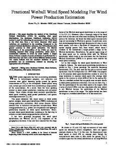
Figure 6: (a) Nonlinear current, (b) Frequency spectrum of non-linear load current, (c) Current of IDEA, (d) Current of utility grid.
end converter, ω e L i edi and ω e L i eqi are the compensation terms for cross coupling effect. The block diagram of the control system has been shown in Fig.5.
Command and estimated speed (PU)
Command d
1
Esimated speed
0.5
0
0
1
2
3
4
5 Time [Sec.]
6
7
8
9
10
7
8
9
10
1 Command and actual P&Q (PU)
VI. SIMULATION RESULTS To show the effectiveness of the proposed method, the proposed system has been simulated using MATLAB/SIMULINK package on a 7.5 kW, 60Hz, 230V wound rotor induction machine. The nonlinear load is modeled by a diode bridge rectifier, which draws a non-linear current from the ac lines. Then, the rotor side controller based on the proposed method has been developed to control the rotor side converter. Wind speed profile is such that it allows the IDEA to work in both sub-synchronous and supersynchronous modes of operation. The command and estimated speed have been shown in Fig.7 (b). The command active power and the reactive power and their actual values have been plotted in Fig.7 (a). It is observed that the harmonics have been removed from the grid lines and the utility current is pure sinusoidal. Response of the system is fast enough for variation of wind speed and to capture the maximum energy of wind. The nonlinear load current and its spectrum, the current of IDEA and the utility current with variation of the wind speed are shown in Fig. 6. The vector control method of FEC has also been simulated. The dc-link voltage command is set at 400V and iqe is set to zero for unity power factor. System response at starting under super synchronous mode of operation is shown in Fig.9. The dc link voltage and its commanded value and also the reactive power current command, iq, are shown in Fig 9 (a0) and Fig. 9 (b), respectively. The FEC current and the input voltage under super synchronous speed with unity power factor have been shown in Fig.8. It is clear that the input current is pure sine wave and the unity power factor is achieved.
1.5
Command active
0.8
0.6 0.4
Actual active
Command and actual reactive
0.2
0
0
1
2
3
4
5 Time [Sec.]
6
Figure 7: (a) Command and estimated speed (pu), (b) Command and actual active and reactive power (pu)
Figure 8: Voltage and current of FEC at super-synchronous speed under unity power factor.
VII. EXPERIMENTAL RESULTS The schematic block diagram of the laboratory experimental setup is given in Fig.10. It consists of a 7.5 kW wound rotor induction machine with its stator connected to
512
230 V, 60 Hz, 3-phase power grid, and the rotor being fed by an IGBT-based PWM converter with front-end diode bridge rectifier. The setup is organized for generating operation where the torque-speed characteristics of the wind turbine are simulated by a 7.5kW dc motor, which is coupled to the IDEA shaft and is driven using a controlled diode rectifier. The dc motor drive works as a nonlinear load and draws a non-sinusoidal current from the grid. A TMS320F2407 fixed point TI DSP based digital control platform is designed and employed for implementing the proposed field oriented control method. The processor runs at a clock frequency of 30 MHz and the sampling frequency used is 50 µs. The software is developed in assembly for fast real-time execution. The non-linear load current and the needed harmonic compensation current are depicted in Fig.11 (a) and Fig. 11 (b), respectively. The rotor current components in the two-phase excitation reference frame are shown in Fig.11(c) and Fig.11 (d). The stator flux angle using section V.2 is calculated and plotted in Fig.12, which varies between 0 and 2π. The rotor angle position is being estimated using the method illustrated in section V.3. The estimated rotor angle current in the stationary reference frame (θ1) and in the rotating reference frame (θ2), and the estimated rotor angle position (θr) are illustrated in Fig.13 (a-c), respectively. The actual rotor angle position measured with optical encoder and the estimated rotor angle position are compared in Fig.14. In Fig. 15, the measured speed using the optical encoder and the estimated speed using the illustrated method in section V.3 are shown. For comparison, in Fig. 14 and Fig.15, the performance of IDEA with and without an optical encoder are shown. All angles are shown in the range of 0 to 2π. The similarity between the sensorless and sensored results is clear. Preliminary laboratory results prove the effectiveness of the proposed method while further experiments are being performed in our laboratory.
+ v as vbs
ibs
Encoder
Is
i*Lbh
TMS320LF2407
DC Motor
Ig
ias
i*Lah
I Lh
DFIG
Figure 10: Schematic block diagram of the experimental setup.
Figure 11: Experimental results: (a) Non-linear load current,(b) Harmonic reference current, (c) q-axis current. (d) d-axis current.
Figure 12: Stator flux angle of IDEA.
(a)
(b)
Figure 9: (a) dc-link voltage at starting under super synchronous speed. (b) qaxis current of FEC at super synchrounos peed.
513
Figure 13: (a) Rotor current angle position in stationary refrence frame, (b) Rotor Current angle position in rotor refrence frame, (c) Esimated rotor angle position.
Figure 14: (a) Actual rotor angle position, (b) Estimated rotor angle position.
5.
L.H. Hansen et al., “Generators and Power Electronics Technology for Wind Turbines,” Proceedings of IECON’01, Denver, Co., 2001.
6.
Clemmensen, “Estimating the cost of Power Quality,” IEEE Spectrum, June 1993.
7.
H. Akagi, “ New Trends in Active Filters for Power Conditioning,” IEEE Transactions on Industry Applications, Vol. 32, No. 6, pp. 13121322, Nov.-Dec. 1996.
8.
F.Z. Peng, H. Akagi, and A. Nabae, “A Novel Harmonic Power Filter,” PESC ’88, pp. 1151-1158, 1996.
9.
S. Battacharya, et-all, “Parallel Active Filter System Implementation and Design Issues for Utility Interface of Adjustable Speed Drive Systems,” IAS’96, pp. 1032-1039, 1996.
10. F. Peng, “Application Issues of Active Power Filters,” IEEE Industry Applications Maganzine, Vol. 4, No. 5, pp. 21-30, Sept.-Oct. 1998. 11. B. Hopfensperger, et-al" stator-flux-oriented control of a doubly-fed induction machine with and without position encoder ",IEE Proc. Electr., Power Appl.,Vol.147,No.4, July 2000. 12. Mehdi T. Abolhassani, P. Enjeti, H.A. Toliyat, “Stator Flux Oriented Control of an Integrated Alternator/Active Filter for Wind Power Applications” IEMDC 2003. 13. Mehdi T. Abolhassani, P. Enjeti, H.A. Toliyat, “A New Electrical Machine for Harmonic Compensation” IECON 2001. 14. Mehdi T. Abolhassani, H.A. Toliyat, P. Enjeti “An Electromechanical Active Filter” IEMDC 2001, Boston, MA. 15. H. Akagi and H. Sato, "Control and Performance of a Doubly-Fed Induction Machine Intended For a flywheel Energy Storage System, IEE Transaction on Power Electronics, Vol.17, No.1, Jan.2002.
16. R. Datta, V.T. Ranganathan, “A Simple Position-Sensorless Algorithm for Rotor-Side Field-Oriented Contrl of Wound-Rotor Induction Machine” IEEE Transaction on Industrial Electronics, Vol.48, No.4, August 2001.
Figure 15: (a) Measured speed using optical encoder. (b) Estimated speed
VIII. CONCLUSIONS A sensorless integrated doubly fed alternator/active filter for grid connected variable speed wind energy conversion system has been developed. With the proposed method, it is possible to capture the maximum wind power while harmonics currents of the utility can simultaneously be compensated. A sensorless stator flux field oriented control was developed to control the rotor side converter of IDEA. This control strategy is capable of controlling the generated active and reactive power plus the amount of harmonic compensation needed by the grid. Vector control method for front-end converter for allowing bi-directional power flow in the rotor circuit has also been developed. Simulation result as well experimental results have proved the effectiveness of the proposed method. REFERENCES 1.
An Integrated Alternator/Active Filter Method and Apparatus, Texas A&M University Patent Disclosure.
2.
I. Takahashi," Universal power distortion compensator using secondary excitation of a rotating Machine' T-IEE Japan, Vol.107-B, No.2, pp7380, 1987.
3.
IEEE Std. 519-1992, “IEEE Recommended Practices and Requirements for Harmonic Control in Electrical Power Systems,” IEEE April 12, 1993.
4.
Electromagnetic Compatibility (EMC) – Part 3: Limits – Section 2: Limits for harmonic current emissions (equipment input current