N.Muthusamy et al. / International Journal of Engineering and Technology (IJET)
Force Measurement on Aircraft Model with and without Winglet using Low Speed Wind Tunnel N.Muthusamy1, S. Vignesh Kumar2,Dr. C. Senthilkumar3 1
Professor,Department of Aeronautical Engineering, Rajalakshmi Engineering College, Chennai-602105,India Email:
[email protected] 3 Assistant Professor, Department of Aerospace Engineering, Madras Institute of Technology, Chennai-600044, India Email:
[email protected] 2 Project Assistant, Department of Aerospace Engineering, Madras Institute of Technology, Chennai, 600044, India Email:
[email protected] Abstract--The objective of the research is to conduct experiment by fabricating a standard aircraft model and retrofit winglets with cant angles 0 degree (vertical),30 degree and 60 degree. The experiments were conducted in a subsonic wind tunnel of size (feet) 3x4x6.The experiment was conducted both for basic model and the model modified with winglets. The model with winglet has exhibited substantial reduction of coefficient of drag. The stall characteristics of the winglet were analyzed by plotting suitable graph. A calibrated three component balance was used for measuring the forces. Automated turntable mounted in the test section of the wind tunnel and therecording systems were used efficiently. The results were compared and discussed. Keyword:Aircraft model, Wind tunnel, Winglet, Vortex, Lift, Drag NOMENCLATURE axial force Coefficient CA CN normal force Coefficient CL lift Coefficient axial CD drag Coefficient CM pitching moment Coefficient CS side force Coefficient CY yawing moment Coefficient ρ Density of air kg/m3 V Velocity of free stream air m/s α Angle of Attack (AOA) q Dynamic pressure c Chord length in mm Re Reynolds number L Length of the model (m) Lref Reference length of the model I. INTRODUCTION It has been a constant endeavor by aviation enthusiasts to improve the wing efficiency. The design of aircraft is limited by the constraints of weight and geometrical feature of aspect ratio. Therefore, any addition or modification to the existing aircraft or in the new design has to be seen in this perspective. In the conventional aircraft the wing tip vortices are responsible for the induced drag due to lower pressure at the upper surface of wing and higher pressure at the lower surface of the wing. The trailing vortices at the wing tip are formed due to airflow caused by the differential pressure below and top of the wing.This is the primary cause for the induced drag which is in the range of about 20% of total drag. To alleviate this problem the researchers have come out with the optimum solution by introduction of devices to overcome the wing tip vortices. Whitcomb was the pioneering researcher in this field of winglet. In his experimental work he has established the wing efficiency has improved by 9% and reduction of drag by 20%. The reduction of induced drag will enhance the range of
ISSN : 0975-4024
Vol 6 No 6 Dec 2014-Jan 2015
2521
N.Muthusamy et al. / International Journal of Engineering and Technology (IJET)
aircraft, performance improvement in handling of aircraft and the cost of operation by saving fuel. The designers has experimented different devices for lift enhancement like wing end plates, upper winglet, lower winglet and multiple winglets. The winglet has become usual phenomena for commercial aircraft in the recent days. The aircrafts all over the world are commercially adopting winglet technology for fuel saving to effect profitable cost of operation. II.REDUCTION OF INDUCED DRAG The induced drag is vital portion of the total components of drag. Any reduction in the induced drag will substantially augment the lift which is essentially needed for aircraft during crucial role of climb. The induced drag is essentially created due to pressure difference between upper and lower surface of the wing. The trailing vortex at the wing tip is the instrumental cause for creation of induced drag. The effort is suitably arrest the creation of vortices by installing winglet at the wing tip.
Fig 1. Vortex formation and Reduction of Induced Drag
III. EXPERIMENTAL SETUP The experiment was conducted at subsonic wind tunnel at Madras Institute of Technology, Chennai,India. It has test section 3 ft × 4 ft and of suction type wind tunnel. The maximum rpm attained by the drive is 1500. The experiments were conducted at rpm range from 300 to 600. Higher rpm was avoided to prevent possible vibration which may lead to inaccurate readings. The aircraft model was mounted in the test section using the automated model mounting mechanism. The automated model mounting mechanism provides both pitching and yawing movement independently. Thesecan be measured for different pitch angles and different electric motor propeller rpm. The model independent movements in pitch (keeping yaw constant) are controlled using a digital TED (touch enabled display) control panel connected to automated mounting mechanism.
Fig 2. Aircraft model with winglet mounted in the wind tunnel test section
ISSN : 0975-4024
Vol 6 No 6 Dec 2014-Jan 2015
2522
N.Muthusamy et al. / International Journal of Engineering and Technology (IJET)
IV. THREE COMPONENT STRAIN GAGE BALANCE The three component balance is an integral RAE type with a maximum diameter of 15mm and length of 210 mm. It is made out of alloy steel 17-4-PH. This has yield strength of 120 Kg/mm2 and UTS of 120 Kg/mm2. The balance consists of two normal force gage stations for determination of normal force, pitching moment and two axial force measuring bridges. The two axial force measuring bridges are externally connected in parallel to give one common averaged output. Balance center is located at the center of the two normal force measuring units.All gage stations are of bending type. Four strain gages are bonded to each of the gage station to form four active arms of Whetstone Bridge. The load specifications for the balance are Axial Force(X direction) 20N (2Kg) Normal Force(Ydirection) 60N (6Kg) Pitching Moment about Z axis 4.5 Nm (450Kgmm)
Fig 3. Schematic diagram of internal three component balance
The balance has been calibrated using calibration test rig facility available at MIT ,Chennai. It was done for very low loads so that the accuracy of results will be high enough to pick up minute forces during the wind tunnel test. The load range used for calibraton is as follows. Axial loading (AF)
0.5 kg (in steps of .05g)
Normal Force (N1)
0.5 kg (in steps of .05g)
Normal Force (N2)
0.5 kg (in steps of .05g)
From the calibration values the inverse co-efficient matrix had been calculated TABLE I Inverse coefficient Matrix
ISSN : 0975-4024
O/pLoad--->
AF
N1
N2
AF N1 N2
2.174596 0.022949 -0.00879
0.048832 3.032325 0.012563
-0.00299 -0.07365 3.098821
Vol 6 No 6 Dec 2014-Jan 2015
2523
N.Muthusamy et al. / International Journal of Engineering and Technology (IJET)
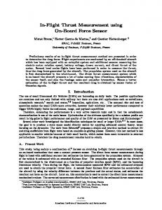
Fig 4.Aircraft model with three dimensional view
In this experiment, wing-body-tail model with and without winglets of suitable scale is fabricated to fit in the test section of the low speed subsonic wind tunnel so as to keep the blockage ratio below 5%. These models are used as standard for checking and controlling the new wind tunnel installations. The model has adequate internal space for setting up three component wind tunnel balance with diameter of 15mm. Airfoils of the wing and airfoils of the horizontal and vertical tails are symmetrical with maximum thickness of 10.5 % at the 37.5% of the chord. Aspect ratio of the wing is 7.31, and its installation angle is 3° with relation to the fuselage axis. It is made into three parts with nose, wing body and the tail assembly. A metallic insert is given to tail part where the adaptor is to be fixed. Winglet has root chord 30mm, tip chord 15mm, sweep angle 40 degrees and height 25 mm. The cant angle is measured with reference to vertical axis. The experiments were conducted for cant angles 0degree (vertical winglet), 30 degrees and 60 degrees. V. DATA ACQUISITION SYSTEM Spider 8-30 is the data acquisition system used for electric measurement of mechanical variables such as strain, force, pressure, path, acceleration and for temperatures. It uses 600 Hz carrier frequency amplifier to manage all measurement tasks with S/G in quarter, half or full bridge connection. All the signal conditioning excitation for passive transducers and amplification, digitization, computer interface and connection technology for a maximum of 8-channels is combined in one-housing. Each channel works with a separate A/D converter which allows measuring rates from 1/s to 9600/s. This means that Spider8 covers the entire range of mechanical measurement tasks. CATMAN professional is the software package used to obtain the aerodynamic forces and moments as a function of time. The following formulae were used for calculation. Calculation of coefficient of lift and drag Coefficient of lift (CL) =C Ncos α −CA sin α Coefficient of drag (CD) =CA sin α + CNcos Coefficient of axial force (CA) = Coeficient of normal force (CN) =
∞ ∗
(
) ∞ ∗
VI. RESULTS ANDDISCUSSION The results of the experiment were plotted for analysis and comparison. The comparison graphs are made by keeping the yaw angle constant. The variation was done on the pitch angle and the free stream velocity. The anglestested werefrom -8 degrees to +16 degrees in the step of 4 degrees. The velocities tested were from 8 m/s to 24 m/s in the steps of 4m/s.The parametric variation for winglet tested were for cant angles 0(vertical winglet), 30 and 60degrees.
ISSN : 0975-4024
Vol 6 No 6 Dec 2014-Jan 2015
2524
N.Muthusamy et al. / International Journal of Engineering and Technology (IJET)
0.8 0.6 0.4
CL
0.2 0 -8
-4
0
4
8
12
16
without winglet
-0.2
0 deg winglet 30 deg winglet
-0.4
60 deg winglet -0.6
AOA Fig 5. Lift coefficient Vs pitch angle at 8 m/s
The graph is plotted for coefficient of lift Vs pitch angle for different winglet cant angles at velocity 8 m/s. The winglet configurations has higher coefficient of lift compared to model without winglet.Vertical winglet and 60 degree winglet are showing significant rise is CL compared to basic model. At negative angles of attack the 30 degree winglet is showing higher lift compared to other configurations. 0.25 without winglet
0.2
0 deg winglet 30 deg winglet
0.15 CD
60 deg winglet
0.1
0.05
0 -8
-4
0
4 AOA
8
12
16
Fig6. Drag coefficientVs angle of attack at velocity 8 m/s
The graph is plotted for coefficient drag and pitch angles. The drag coefficient graphis drawn at velocity 8m/s. The graph shows substantial reduction in the drag for the model fitted with different winglet cant angles.The vertical winglet exhibits more drag reduction compared to otherwinglets. At high angles of attack the 30 degree winglet is exhibiting lowest drag.
ISSN : 0975-4024
Vol 6 No 6 Dec 2014-Jan 2015
2525
N.Muthusamy et al. / International Journal of Engineering and Technology (IJET)
0.8 0.6 0.4
CL
0.2 0 -8
-4
0
4
8
-0.2
12
16
without winglet 0 deg winglet
-0.4
30 deg winglet 60 deg winglet
-0.6 -0.8
AOA
Fig 7. Lift coefficient Vs pitch angle at 12m/s
The plot is drawn for velocity at12m/s.At this velocity the winglet with 60 degrees showing increased lift coefficient compared to other winglet configurations. This is more noticeable at high angles of attack. 0.25
0.2
without winglet 0 deg winglet 30 deg winglet
0.15 CD
60 deg winglet 0.1
0.05
0 -8
-4
0
4 AOA
8
12
16
Fig 8.Drag coefficient vs angle of attack at velocity 12 m/s
The plotting is done for wind tunnel velocity of 12m/s.The coefficient of drag for the winglets with different configurations are lesser compared to the basic model. It once again reinforces that the winglet produces decrease in drag compared to the model without winglet.
ISSN : 0975-4024
Vol 6 No 6 Dec 2014-Jan 2015
2526
N.Muthusamy et al. / International Journal of Engineering and Technology (IJET)
1 0.8 0.6 0.4
CL
0.2 0 -8
-4
0
4
8
-0.2
12
16
without winglet 0 deg winglet
-0.4
30 deg winglet -0.6
60 deg winglet
-0.8
AOA
Fig 9.Lift coefficient Vs pitch angle at velocity 16m/s
At velocity 16m/s for the negative angles of attack not much variationin CL is exhibited. At higher angles attack the winglet performance is noticeable in increasing lift coefficient compared to basic model. 0.25 without winglet 0 deg winglet
0.2
30 deg winglet 60 deg winglet
CD
0.15
0.1
0.05
0 -8
-4
0
4 AOA
8
12
16
Fig10. Coefficient of drag Vs angle of attack at velocity 16m/s
The graph is plotted for velocity at 16 m/s. Around 8 degrees sudden increase in drag of basic model is noticed. The winglets are contributing to reduction of drag as exhibited in the graph.
ISSN : 0975-4024
Vol 6 No 6 Dec 2014-Jan 2015
2527
N.Muthusamy et al. / International Journal of Engineering and Technology (IJET)
0.8 0.6 0.4
CL
0.2 0
-8
-4
0
4
8
12
16
-0.2 without winglet
-0.4
0 deg winglet 30 deg winglet
-0.6
60 deg winglet
-0.8
AOA
Fig11. Lift coefficient Vs pitch angle velocity at 20 m/s
The graph is plotted for velocity at 20 m/s. throughout the range of angles of attack the vertical winglet is showing high lift coefficient. Around 16 degrees of angle of attack, the pattern of graph for winglets are different. The basic model has tendency to stall at high angle of attack is observed. 0.25 without winglet 0.2
0 deg winglet 30 deg winglet 60 deg winglet
CD
0.15
0.1
0.05
0 -8
-4
0
4 AOA
8
12
16
Fig. 12. Drag coefficient Vs angle of attack at velocity at 20 m/s
The graph plotting is done for the wind tunnel speed at 20m/s. At high velocity the coefficient of drag for different winglet are distinctly noticed. The vertical winglet continues to exhibit low drag coefficient compared to the other winglets throughout the range of angles of attack.
ISSN : 0975-4024
Vol 6 No 6 Dec 2014-Jan 2015
2528
N.Muthusamy et al. / International Journal of Engineering and Technology (IJET)
1 0.8 0.6
CL
0.4 0.2 0 -8
-4
0
4
8
12
16
-0.2 without winglet
-0.4
0 deg winglet 30 deg winglet
-0.6
60 deg winglet -0.8 -1
AOA
Fig 13. Lift coefficient Vs pitch angle for velocity at 24m/s
The coefficient of lift is showing similar trend for all winglet configurations. The winglet with 60 degree is showing stall characteristics at high angle of attack. The basic model also has tendency to stall at high angle of attack. This is continuation of what was noticed at 20 m/s for lift curve. The winglet with 30 degree cant angle has improved stall characteristics. 0.25
without winglet
0.2
0 deg winglet 30 deg winglet 60 deg winglet
CD
0.15
0.1
0.05
0 -8
-4
0
4 AOA
8
12
16
Fig 14. Drag coefficient Vs pitch angle for velocity at 24 m/s
The graph is plotted for subsonic speed of 24 m/s. The graph shows sustained trend of reduction of coefficient of drag for different cant angles at 24 m/s. The winglet with 60 degree shows high slope of drag compared to other winglet configurations. The basic model also exhibits high slope dragcoefficientindicative of stall characteristics.
ISSN : 0975-4024
Vol 6 No 6 Dec 2014-Jan 2015
2529
N.Muthusamy et al. / International Journal of Engineering and Technology (IJET)
VII. CONCLUSION The experimental investigation of winglet effects on aircraft model were conducted at subsonic wind tunnel .The parametric three variation of winglet angles were chosen for the model. The testing was done for the basic model and winglet having cant angles 0(vertical winglet),30 and 60 degrees. The testing was done for pitch angle varying from -8 degrees to +16 degrees. The models were tested at speeds ranging from 8 m/s to 24 m/s in steps of 4m/s. The vertical winglet contribution of coefficient of lift was significant. It has been observed at high speeds the model with vertical winglet (0 cant angle) and 30 degree exhibits strong anti stall characteristics. 60 degree winglet cant angle is not a desirable fitment. REFERENCES [1] [2] [3] [4] [5] [6] [7] [8] [9] [10] [11]
[12] [13]
[14]
Binion, T.W., (1976), “Tests of the ONERA Calibration Models in Three Transonic Wind Tunnels”, AIAA, 14th. Aerospace Science meeting. Ocokoljic, G., (2004), “Testing of the Calibration Model ONERA M4 in Subsonic Wind Tunnel T-35”, Scientific Technical Review, Vol. No.3-4. Reeder M.F, Allen, W. Philips J.M, and Dimmick R., (2007), “Wind-Tunnel Measurements of the E-8c Modeled With and Without Winglets”, AIAA Paper 2007-1633 Van Dam, C.P., Holmes, P.J. and Pitts, C., (1981), “Effect of Winglets on Performance and Handling Qualities of General Aviation Aircraft”, AIAA Journal of Aircraft, Vol. 18 No. 7, July 1981, pp. 587-591. Whitcomb, R.T., (1997), “A Design Approach and Selected Wind-Tunnel Result at High Subsonic Speed for Wing-Tip Mounted Winglets,” NASA TN D-8260. Bernhard Roglin and Joseph Katz(2001),"Study of Downward Pointing Winglets for Unwept Wings"39th Aerospace Sciences Meeting ,8-11 January 2001,AIAA 2001-0268. YU Jun-li,WANG Lin-lin and GAO Ge(2006),"Using Wing Tip Devices to Improve Performance of Saucer-Shaped Aircraft", Chinese Journal of Aeronautics,Vol 19 No.4,November 2006,pp 306-314 Maughmer M.D, Swan T.S. and Willits,S.M. (2001),"The Design and Testing of a Winglet Airfoil for Low-Speed Aircraft",19th AIAA Applied Aerodynamics Conference 11-14 June 2001,Anaheim,California,AIAA 2001-2478 H.D.Ceron-Munoz, R.Cosin and R.F.F.Coimbra (2013),"Experimental Investigation of Wing-Tip Devices on the Reduction of Induced Drag" Journal of Aircraft Vo.50,No. 2,March-April 2013,pp441-449 P.Anderle, F.N.Coton, L. Smrcekand V. Broz (2004) ,"A Wind Tunnel Based Study of the Flow Field behind Sailplane Winglets",24th International Congress of the Aeronautical Sciences. Committee on Assessment of Aircraft Winglets for Large Aircraft Fuel Efficiency, National Research Council of the National Academies Report(2007) on Assessment of Wingtip Modifications to increase the fuel efficiency of Air Force Aircraft. The National Academies Press, Washington DC. Bento S. de Mattos ,Antonini P. Macedo and Durval H. da Silva Filho,"Considerations about Winglet Design" 21st Applied Aerodynamics Conference 23-26 June 2003 ,Florida AIAA 2003-3502 AltabHossaina, Prithvi Raj Arora, Abdul Aziz Jaafar, A.K.M. ParvezIqbal, and AtaurRahman (2006) "Winglet Technology for the Modern Aircraft "Proceedings of the 3rd BSME-ASME International Conference on Thermal Engineering 20-22 December, 2006, Dhaka, Bangladesh NurulainYahaya and JamaluddinMdSheriff(2012),"Flow Behaviour Around Winglets", Journal of Mekanikal,June 2012,No.34,pp 95100
ISSN : 0975-4024
Vol 6 No 6 Dec 2014-Jan 2015
2530