fully automated manner using the COMPASS toolset [8] . It supports modern model checking techniques [4] for checking correctness, advanced safety analysis ...
Formal Correctness, Safety, Dependability, and Performance Analysis of a Satellite Marie-Aude Esteve∗ , Joost-Pieter Katoen†‡ , Viet Yen Nguyen† , Bart Postma‡ and Yuri Yushtein∗ ∗ Software Systems Engineering Section, European Space Agency/ESTEC, The Netherlands Email: {marie-aude.esteve,yuri.yushtein}@esa.int † Software Modeling and Verification Group, RWTH Aachen University, Germany Email: {katoen,nguyen}@cs.rwth-aachen.de ‡ Formal Methods and Tools Group, University of Twente, The Netherlands Email: {b.c.postma}@student.utwente.nl
Abstract—This paper reports on the usage of a broad palette of formal modeling and analysis techniques on a regular industrial-size design of an ultra-modern satellite platform. These efforts were carried out in parallel with the conventional software development of the satellite platform. The model itself is expressed in a formalized dialect of AADL. Its formal nature enables rigorous and automated analysis, for which the recently developed COMPASS toolset was used. The whole effort revealed numerous inconsistencies in the early design documents, and the use of formal analyses provided additional insight on discrete system behavior (comprising nearly 50 million states), on hybrid system behavior involving discrete and continuous variables, and enabled the automated generation of large fault trees (66 nodes) for safety analysis that typically are constructed by hand. The model’s size pushed the computational tractability of the algorithms underlying the formal analyses, and revealed bottlenecks for future theoretical research. Additionally, the effort led to newly learned practices from which subsequent formal modeling and analysis efforts shall benefit, especially when they are injected in the conventional software development lifecycle. The case demonstrates the feasibility of fully capturing a system-level design as a single comprehensive formal model and analyze it automatically using a toolset based on (probabilistic) model checkers. Keywords-formal methods; satellite; model checking; safety; dependability; performance; FDIR; fault management;
I. I NTRODUCTION Building modern spacecrafts is highly demanding. They should be extremely dependable and they must offer service without interruption (i.e. without failure) for a very long time – typically years or decades – and in the harsh environment of space. Failures are costly and may severely damage reputations. Rigorous design support and analysis techniques are thus called for. Design mistakes must be found as early as possible in the design process while performance and reliability guarantees need to be checked whenever possible. Tailored effective techniques exist for specific systemlevel aspects. Peer reviewing and extensive testing find most of the software bugs, performance is checked using discrete event simulation, and hardware safety levels are analyzed using a profiled Failure Modes, Effects and Criticality Analysis (FMECA) approach. That is the current state of industrial practice. But how is the consistency ensured if
the input models are tailored to reflect a single aspect? What is the relevance of a 98.7% availability if its analysis overconservatively abstracts from degraded modes of operations? There is a clear need for an integrated, coherent approach. This is easier said than done. The inherently heterogeneous character of on-board systems involving software, sensors, actuators, hydraulics, electrical components, etc., each with its own specific development approach and artifacts, severely complicates this. About three years ago a small consortium consisting of government, academia and industry took up this challenge. Within the European Space Agency-funded COMPASS (COrrectness, Modeling and Performance of Aerospace SyStems) project [8], an overarching model-based approach has been developed. The key is to model spacecrafts at an adequate level of abstraction using a general-purpose modeling and specification formalism based on Architecture Analysis & Design Language (AADL) as standardized by SAE International. Ambiguities about the meaning of designs are abandoned by a rigorous formal semantics. Among the system aspects that can be modeled are (timed) hardware operations, software operations (supporting processes and threads), continuous variables (such as temperature) and faults with probabilistic failure rates. A complete system specification describes three parts: nominal behavior, error behavior, and a fault injection specifying how the error behavior influences the system’s nominal behavior. Systems are described in a component-based manner such that the structure of system models strongly resembles the real system structure. This coherent and multidisciplinary modeling approach is complemented by a comprehensive palette of analysis techniques. The richness of the AADL dialect gives the power to specify and generate a single system model that can be analyzed for multiple qualities: reliability, availability, safety, performance, and their mixture. All analysis outcomes are related to the same system model, thus ensuring coherency and consistency. Most importantly though, is that many of these analyses can be carried out in a fully automated manner using the COMPASS toolset [8] . It supports modern model checking techniques [4] for checking correctness, advanced safety analysis techniques to generate
static and dynamic fault trees [5], the automated generation of FMECA tables, automated diagnosability analysis, and the generation of key performance indices using probabilistic model checking [3]. In this paper, our contribution is the report on our modeling and analysis effort of a modern satellite platform under development using the aforementioned toolset. The effort is motivated by the challenges encountered in the conventional space software development (cf. §II). By using the COMPASS toolset (described in §III), we constructed from the early (volatile) design documents of a satellite platform in development (outlined in §IV) a substantial system-level model of nearly 4,000 lines with a nominal behavior of nearly 50 million states. The modeling process itself (cf. §V-A), the formalization of the requirements (cf. §V-B) and correctness, safety, dependability and performance analyses performed on the model (cf. §VI) revealed inconsistencies in the design documents which were provided as feedback to the satellite development team. It also showed the current limits of the modeling language and the algorithms underlying the analyses, providing the scientific community input for future work. Furthermore, we developed new practices which benefit future formal modeling and analysis efforts, especially when they are injected in the conventional development (cf. §VII). The project took six months in total – including the learning curve of AADL and the COMPASS toolset – and was carried out by (on average) 1.5 persons. II. S PACE S OFTWARE E NGINEERING Spacecraft operations have different degrees of on-board automation depending on factors such as mission type, mission objectives and priorities, type of the spacecraft orbit, spacecraft ground visibility profile, operations concepts and communication constraints. These factors contribute to the trade-off on the distribution of responsibilities and the corresponding required capabilities of the ground stations versus the autonomous spacecraft operation. For example, communication satellites placed in the geostationary orbit have continuous ground visibility with very small communication delay. If needed, they can be operated in real-time (tele-operated). However, due to their mission objectives, they have very high availability requirements, as loss of service has economical, and sometimes safety, consequences. Another example are Earth observation spacecrafts. They typically orbit in the low Earth orbit, having intermittent visibility by the ground stations during the flyovers. These missions are characterized by the massive amount of observation data to be processed and downlinked. As this cannot be performed continuously due to the short visibility windows, continued data collection and data integrity shall be ensured between the communication sessions. Lastly, science and robotic exploration missions take spacecrafts farther into space and further away from the possibility of direct Earth intervention as communication bandwidth
decreases and communication latency increases, putting ever increasing focus on the spacecraft self-reliance. In the context of the increasing spacecraft autonomy demands, the spacecraft capability to sustain the continued operation in the presence of failures and anomalies plays a central role. Failure Detection, Isolation and Recovery (FDIR) systems ensure that the mission objectives and constraints in terms of dependability and safety are met, and ultimately to protect the spacecraft from the failure scenarios leading to the spacecraft’s loss. The FDIR system plays the role of a supervisory controller restricting the system behavior from the undesired scenarios. FDIR operations are based on system monitoring through the available onboard observations, diagnosis of the off-nominal conditions and initiation of the recovery procedures. These procedures are designed to restore the spacecraft operation to nominal conditions if feasible, to a degraded operation if possible, or to put the spacecraft into a known safe configuration. The latter is only used to safeguard the system and to transfer control to the ground station for further handling. Current practices of FDIR development are derived from the development processes that are standardized in the form of the European Cooperation for Space Standardization (ECSS) as available from ecss.nl. The practices utilize the results of the system Reliability, Availability, Maintainability and Safety (RAMS) analyses, such as Failure Modes Effects and Criticality Analysis, Fault Tree Analysis (FTA) and Hardware-Software Interaction Analysis (HSIA). However, data for these analyses become available later in the engineering process when software development has already passed its initial phases. This makes the introduction of software FDIR components in the overall software architectural design a challenging matter. Moreover, changes in the subsystems design, their fault modes, and possible fault combinations and scenarios, hamper the process of achieving a stable FDIR design. System testing is also a challenging process from the FDIR perspective due to physical limitations in the ability to reproduce all the possible faults and their combinations during the test campaigns. Additional challenges in FDIR development are posed by the often partial system observability by the FDIR subsystems, the continuous nature of particular processes and values being monitored (implying necessity for the adequate approaches to their reliable detection, and consistency in the sets of detection thresholds for reliable diagnosis), and general system diagnosability issues. The latter hinders the FDIR verification for correctness and completeness, negatively affecting the false alarm rates—both negative and positive ones. For the distributed or layered FDIR architectures adequacy of the overall (system-level) FDIR operation shall be assured through consistency of the actions at the local FDIR elements. The FDIR design strongly depends on the spacecraft operational modes and mission phases. Accordingly, the
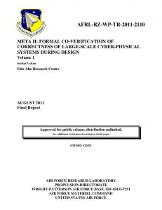
Nominal Model
Error Model
Fault Injections
Req's (patterns)
Extended Model
Formal Canonical Models State Space
Markov Chain
Req's (logic)
NuSMV
Correctness
FDIR Effectiveness
Safety/ Depend.
Performability
Figure 1. COMPASS approach. The rhomboid shapes are the inputs, the rounded rectangles are the intermediate artifacts derived through transformation and the unrounded rectangles are the outputs/analyses.
FDIR system has to handle – typically hundreds to thousands of – recovery procedures each appropriate to the current state of the spacecraft. This usually leads to a multitude of exceptions in the FDIR processing. Moreover, local implementations of the FDIR system elements in separate equipments, units, and subsystems imply the need for coordination logic and measures to be put in place. These matters, including the additional timing dimension, result in the high overall FDIR complexity, limiting the possibility for the fault coverage analysis, and impairing effective verification & validation process. III. F ORMAL M ETHODS & T OOLS FOR S PACE I NDUSTRY Formal methods come with the rigor that is needed to overcome the challenges of developing FDIR systems. It emphasizes proof-oriented verification and its mathematical underpinnings allows for a high degree of automated analysis. In 2008, the COMPASS consortium developed a formal modeling and analysis toolset specifically addressing the needs of the (European) space industry. The result is a graphical toolset-supported modeling-requirement-analysis approach (cf. figure 1). In this section, only a brief overview of COMPASS is presented. A full description can be found in [8]. Modeling Language: To warrant design acceptance by engineers in the aerospace industry (and other engineering domains), the COMPASS approach is based on AADL, a design formalism that is standardized by the Society of Automotive Engineers [14]. It is used to capture a system from an architectural perspective, at which the abstractionlevel reasons over software (e.g. processes and threads) and hardware (e.g. processors and buses) components. The components are arranged in a super/sub componenthierarchy, respectively representing top-down system refinement. Components interact through typed event and data
port connections and the interaction itself is defined by a mode transition system, akin to a state machine. Modes can be annotated with real-time and hybrid behavior, allowing for capturing systems with continuous physical dynamics such as mechanics and hydraulics. There is built-in support for dynamic reconfiguration that allows for the activation and deactivation of subcomponents and port connections depending on current mode. A dynamic reconfiguration represents an on-the-fly change in the system topology and is a strategy often used to cope with faults and errors. All the aforementioned is only used to capture nominal behavior. For degraded and failing behavior, AADL provides error models as an extension. Error models define a probabilistic state machine where states represent fault modes and the transitions between are faults whose occurrences are governed by Poisson rates. Errors can propagate to other components by matching incoming with outgoing error events. System repairs can be modeled using reset events. Nominal AADL models are oblivious to error models unless a failure is injected: this links a fault in the error model to an user-defined data-corruption in the nominal model. A nominal model, an error model and the fault injections that link them are integrated into a single model called the extended model. The latter represents the nominal, degraded and failure operations of the system. In COMPASS, the extended model is equipped with a formal semantics [7] that provides precise and unambiguous meaning in terms of a state space containing action, stochastic and timed transitions. To avoid confusion with AADL, which has no comprehensive formal semantics, the formal semantics and the scope of supported syntax is christened SLIM, the System-Level Integrated Modeling language. Requirements: In traditional formal methods approaches, engineers express requirements in a temporal logic fitting to the analysis. Mastering a particular logic comes with a steep learning curve. When Dywer et al. surveyed requirement documents [13], they noticed that a majority of them could be captured in (just) seven patterns. The patterns are suitable for non-expert users, yet have a direct translation to the temporal logics. Grunske did a similar survey [15] on risk and performance requirements, and developed a set of eight patterns that are translatable to Continuous Stochastic Logic [3], a temporal logic that allows statements about timing and probabilities. In COMPASS, these patterns are graphically presented in prose-form containing blanks. The blanks are input fields that the user fills in to complete the prose representing the requirement. When needed, the toolset automatically transforms the filled patterns to a logical formula. This way, the user is not exposed to the logics. Analysis: The extended SLIM model and the requirements are the input for various analyses. Through the COMPASS graphical interface, the user can do the following: Functional Verification – comprises random and userguided simulation, deadlock detection and the verification
of functional properties via model checking (also known as exhaustive testing) [4]. For the latter two, the output is that a deadlock is absent respectively the property holds, or a trace that represents a counterexample proving the presence of a deadlock or refuting the property. Safety & Dependability Analysis – comprises the automated generation of traditional safety & dependability artifacts [9], namely dynamic fault trees (FTA) and failure modes and effects tables (FMEA). FTA is a deductive analysis where the user provides a top-level event (e.g. undesired system state) and the COMPASS tool then reasons backwards to compute all possible combinations of basic faults that lead to that state. The output is a tree-shaped diagram composed of OR, AND, and ordered AND operators. FMEA is the inductive equivalent of FTA and it is the same as FMECA without criticality analysis. It computes, given a fault combination provided by the engineer, the causal effects on the system upon occurrence of that combination. FDIR Effectiveness – fault detection analysis computes which data lines are triggered upon a failure. Fault isolation analysis relates the possible fault configuration to a triggered data line. Diagnosability analysis [11] checks whether a system (or a component) provides sufficient data output lines for another system to infer a correct belief failure state. It can also be used to cut off data output lines (and consequently costs) by checking whether the removal of a data output line impacts the inference of belief failure states. Performability – determines system performance by computing probabilities of events (e.g. failures, recoveries) under degraded operations. It furthermore includes the evaluation of fault trees by computing the probabilities of top-level events [5]. The COMPASS toolset performs a series of behind-thescenes model transformations to inputs for NuSMV [10] and MRMC [16]. Both are model checkers that cover discrete, real-timed, hybrid and through linking both, also probabilistic systems. The model checkers are the generic engines performing the analyses stated above. The user however does not need to interact with them. Their outputs are transformed back to symbols and identifiers at SLIM level, and as such the user only needs to operate with the COMPASS graphical interface. IV. C ASE S TUDY: S ATELLITE P LATFORM Industrial case studies have been conducted earlier within the COMPASS project, such as a satellite’s FDIR mode management system and a satellite’s thermal regulation system [6]. These studies were focussed on critical parts of satellite, and did not cover the full functionality of a satellite platform such as the interaction between several subsystems. This section presents a newer and more comprehensive case study covering a satellite platform that is currently under development. Due to the confidential nature of the case, the model is not publicly available.
Satellite Payload Control & Data Unit
Platform Onboard Data Handling
CDU OBDH
RM
TT&C
AOCS
OCS
EPS
Telemetry, Tracking & Command Propulsion
Reconfiguration Module Attitude & Orbit Control System Power
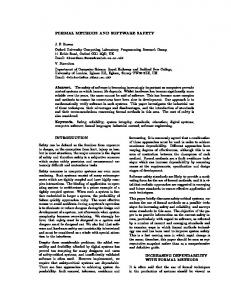
Figure 2. Decomposition of the case study’s satellite. OCS consists of a series of controllable thrusters for orbital corrections. AOCS is a controlsystem consisting of several kinds of sensors for acquiring and maintaining a correct attitude and orbit. CDU is the main computer. EPS consists of solar arrays and batteries for powering both the platform and the payload. TT&C is the radio communication interface for ground control on Earth.
A. Satellite Overview At the highest conceptual level, the satellite is composed of the payload and the platform. The payload comprises mission-specific subsystems and the platform contains all subsystems needed to keep the satellite orbiting in space (cf. Figure 2). The payload is usually designed and tailored from scratch, whereas for the platform lots of design heritage applies. For this reason, our case study focuses on a SLIM model of the platform, as this might benefit future projects too. A decomposition of the platform into selected subsystems is shown in Figure 2. The majority of these subsystems are designed with degrees of fault-tolerance, depending on the criticality of the subsystem. Redundancy with reconfigurations, correcting codes and compensation procedures are part of comprehensive strategies for achieving fault-tolerance. In the extreme case, the satellite should survive a particular number of days without ground intervention assuming no additional failure occurs. As faults could occur at any level in the system’s hierarchy (system, subsystem, equipment), the FDIR system obeys a cross-cutting design, where the complexity is handled in levels. The lowest level represents minor failures and their recoveries are handled transparently w.r.t. other subsystems. Failures in the subsequent level can be isolated to single subsystems and recovery is the responsibility of the software. The next level represents failure of multiple subsystems, which is also handled by the software. The remaining levels are hardware failures and its recovery are performed via dedicated reconfiguration modules. A design of a FDIR mechanism that handles all these levels undergoes a rigorous review process to ensure its correctness.
B. Objectives We started our case study at the Preliminary Design Review stage of the satellite project, where the details of design started to mature. In the traditional space engineering process, several objectives have to be met in order to proceed to the Critical Design stage, among which the following are of interest to us and thus within the scope of this case study: • compliance of the preliminary design with the functional and operational requirements and justifications. • demonstration of compliance with preliminary reliability, availability, failure tolerance, and failure propagation requirements, consistency with redundancy and FDIR approach implementation (HW/SW). And evidence of tracking/implementation of preliminary RAMS recommendations. • consistency and completeness of the preliminary RAMS analyses. • completeness, credibility, and consistency of the preliminary design. The satellite’s development team was on a strict schedule, and hence it would be unwise to inject novel development approaches – like our initiative – into the production process. We ran our case study in parallel with the actual development as an experimental side-track so that we enjoyed availability of fresh design information, while meeting our own additional objectives: • Reference model: obtaining a formal model of a satellite platform as a reference for future formal modeling. • Toolset capability: obtaining a model that pushes the limits of the COMPASS toolset and revealing directions for further research. • Modeling guidelines: develop best practices for effective (e.g. fast) formal analysis using model checking techniques. • Improve software development lifecycle: understand how formal analysis supplements and/or replaces existing practices as defined in ECSS E-40 [12] (European Standard on Space Software Engineering). In particular, to understand the impact of increasing design maturity on formal modeling. Note that for the latter, it is imperative that the case study is run in parallel with the system’s active development. If our case study were run after its realization, the effort became an afterthought in which design information has fully crystalized and matured. V. M ODELING & S PECIFICATION The case study was conducted in a time-frame of six months, which includes the learning curve to understand the SLIM modeling language and the COMPASS toolset. Our modeler has a master-level education in software engineering and had only basic knowledge on model checking. He was supported by the members of the COMPASS consortium
Table I M ETRICS OF THE FULL SATELLITE PLATFORM MODEL AND REQUIREMENTS . Scope
Model
Requirements
Metric Components Ports Modes Error models Recoveries Nominal state space LOC (without comments) Propositional Absence Universality Response Probabilistic Invariance Probabilistic Existence
Count 86 937 244 20 16 48421100 3831 25 2 1 14 1 1
during the modelling process. In this section, we highlight the modeling (cf. §V-A) and requirements specification (cf. §V-B). A. Modeling The overall composite system is described by two modes: nominal and safe. The nominal mode describes a set of satellite configurations in which the system functions within nominal conditions. Upon the detection of faults, recoveries might be attempted for resuming nominal operation. Otherwise a transition is made into safe mode for which the system reconfigures itself for survival. This important transition has system-level effects and hence is critical. In the remainder of this paper this important event is called TLE-1 (first top-level event). During modeling, we focused on a subsystem/equipment at a time as the design of each corresponded more or less to a specific (section of a) design and a requirements document. We progressively increased coverage by adding more detailed subsystems to the overall model, while keeping highlevel abstractions or stubs for the remaining subsystems. The metrics of the full model are described in the upper part of Table I. Due to the page limit, we will only highlight modeling aspects and practices. 1) Discretization: Various design aspects are often specified in terms of ranges. Like for the sun sensors, ranges are used in degrees of sun ray impact to determine exposure to the sun. For the power system, over-currents are specified by voltage transfer functions. To avoid a combinatorial explosion of the state space, these ranges have to be abstracted with respect to the desired functionality, e.g. a boolean indicating sun exposure (or not) and respectively a boolean indicating over-current (or not). Enumerations are used when there are gradations within the ranges. 2) Timing: Real-time correctness is an important aspect for various subsystems, especially with regard to the recovery procedures. For example, the recovery modules contain a table of Programmable Alarm Patterns (PAP), which
upon a match looks up a corresponding recovery procedure which is described by a Compressed Command Sequence (CCS). Each individual command in a recovery procedure is annotated with its maximum task duration. To enforce this timing behavior in our model, a timer is added and transition guards over the timer are defined. If only guards were used, it would be possible for the system to stay in a mode forever (i.e. time divergence). To avoid this, mode invariants are added to force a transition when the invariant becomes invalid by the passage of time. A second concern with modeling timed aspects is to ensure the absence of Zeno behavior. Otherwise the model could take infinitely many steps within a finite time-span. The presence of timedivergence and Zeno behavior leads to invalid outputs, and hence their absence needs to be ensured. This is elaborated and discussed in section VII. 3) Hybridity: Hybrid aspects (e.g. temperature evolution or fluid pressure) are a generalization of real-time constraints. They need to be incorporated into the model without discretization if one wants to check compliance of range requirements, e.g., the temperature stays between a lower and upper limit in the presence of a (redundant) heating system. To ensure computational tractability [1], the COMPASS toolset only supports simple linear differential equations for time-dependent evolution. As many equations are not specified in this form, the engineer needs to abstract the original equations into linear ones. Additionally, the concerns of Zeno behavior and time-divergence also apply in a similar fashion to hybrid models. 4) Reconfiguration: SLIM offers mode-dependent activations as a first-class language construct, allowing the enabling/disabling of components based on the current mode. Fault tolerance by redundancy can thus be easily expressed by modeling multiple components of equal functionality which are active in disjunct modes, like two processor modules being active in respectively the nominal and safe mode. Events from a recovery procedure can trigger transitions between the modes, resulting in a reconfiguration of the system topology. 5) Errors and Fault Injections: The primary source for error modeling is the preliminary FMECA. It lists the possible detectable failures as an event and relates it to the effect on the system. This mapping is nearly equal to the fault injections. It also provides the information for constructing the error models. We found that in all cases, the probabilistic behavior was either shaped as a single step from an errorfree state to an error state (so-called permanent errors), or that they follow a fault-repair loop-structure on the errorfree/error states (so-called transient errors). The FMECA is also the source for failure rates. They are expressed in failures in time (FIT), which indicates the expected number of failures in 109 hours. 6) Assumptions: At first sight, the amount of design information is so overwhelming, that it is inconceivable to
comprehend the system all at once, especially if one is not familiar with the system under development. Information might be perceived as incomplete, unclear, or wrong due to this, and this delays the modeling phase. We developed a practice of quickly continuing modeling using assumptive modeling decisions (Assumptions) and tracking those in a spreadsheet. In addition to that, we also tracked parts of the design documents that were easily modeled (Direct Conversion), parts that were intentionally abstracted (Abstraction) and parts that were not modeled (Underspecified). When a design choice was clarified, the assumption was resolved (Explained). 7) Traceability: For any system under development, and especially in the preliminary design phase, the design is susceptible to changes. Every few months a new version of design documents is distributed with detailed change-logs. To keep track of the changes, we maintained a traceability spreadsheet that maps each SLIM part to the corresponding points in the design documents. Upon a new revision, we simply traversed the change-logs, pinpointed the affected parts in the SLIM model and updated them to reflect the change accordingly. B. Requirements Specification Requirements documents are developed for all parts of the satellite at all levels (system, subsystem, equipment). As we were in the preliminary design review phase, the requirements were not fully detailed and still in proseform like “FDIR functions must be active in all AOCS modes”. Due to this shape, not all of them are amenable for formal analysis. From the several thousands of requirements, we analyzed 106 requirements and checked whether they specify behavior (as requirements can also state physical structural constraints), whether they were not underspecified (requirements might lack sufficient detail) and whether they are within scope (requirements can relate to payload). From the 106 requirements, 24 were suitable and used for our model. Once deemed suitable, they had to be mapped to a specification pattern. In many cases, clarifications are needed during the mapping. For example, which analysis (and why) is suitable for verification? What are the applicable modeled components? What constitutes the atomic propositions (e.g. what is exactly a FDIR function)? Hence for the analysis and mapping of requirements, we additionally maintained an assumptions spreadsheet and a traceability spreadsheet, just like we did for modeling. Similar to the studies in [13], [15], we tracked the kind of patterns used and these are shown in the lower part of Table I. VI. A NALYSES Modeling is highly intertwined with analysis, since the output from analysis provides valuable information for possible refinements of the model. The most widely-used analysis method during modeling is model simulation, as
3
Single earth sensor signal failure
Multiplication of state space
1
Number of injections
11
Double earth sensors signal failure
2 35
Propulsion failure
5
AOCS equipments failure
213563 7 16
All reactionwheel failures
8
Single reactionwheel failure
10 8
Processor module failures
10
1372 11 14
Complete earth sensor failure
172
Reactionwheel + earth sensor failures
22 1
10
100
1000
10000
100000
1000000
Figure 3. Degrees of state space increase with respect to nominal state space size when injecting failures. The scale is logarithmic.
inspection of traces is a fast sanity check before running a resource-consuming analysis. During all analyses, particular sets of fault injections were disabled/enabled depending on the aim. This was needed for this case study as we observed that fault injections lead to a significant increase of the state space (see Figure 3). This is not surprising. A fault injection basically yields the crossproduct of the subsystem to which the error is injected, and the error model [8]. There is no direct correlation between the amount of fault injections and the increase, although there is a relation between the kind of fault injections and the increase. Fault injections that have system-level impact (e.g. processor module failures) add more behavior than fault injections with lower-level impact (e.g. Earth sensor failures) as they affect a larger fragment of the state space. All analyses were run on a set of identical computers running 64-bits Linux, each with a 2.1 GHz AMD Opteron CPU and 192 GB RAM. The consumption of peak resources for each analysis is shown in Table II. Functional Verification: we separated this into two activities: discrete and real-time/hybrid verification. During the verification of the discrete part, which is the majority of the model, we verified 16 properties. Noteworthy here is that the COMPASS toolset does verification in the absence of any fairness constraints. Occasionally, it would be useful to express those to avoid starvation of components. Now we had to embed the constraints in the model instead, which slightly increases its size due to the added synchronization. The real-time/hybrid parts of the model are relatively small and were joined together into a single hybrid model. This alternative model was developed to check a requirement stating that the redundant heater is only active in degraded operations. Verifying this requires the bounded model checking backend [2] and we experimented with increasing bounds to measure the limit (cf. table II). With
respect to the increasing bounds, we measured that the time needed grows exponentially and memory-wise the growth is linear. We stopped our measurements at bound 79, as this exhausted our machine. Safety & Dependability: the platform’s most critical event that affects safety and dependability is TLE-1, i.e. the transition to safe mode. The transition is triggered upon the occurrence of severe failures. In the design documents, a (static) fault tree of 66 nodes is provided relating TLE1 with the failures. Using our toolset, we could produce the same (static) fault tree from our SLIM model in a fully automated manner. We also generated a fault tree for the setting of the fail-operational flag. This flag indicates that the satellite’s payload services might be impaired due to platform failures. The dynamic variant of fault tree analysis delivered similar results. In two cases, it delivered them with less computation time. This came to us as a surprise, given that the dynamic aspect is an additional analysis upon static fault tree generation. The internal logs of the COMPASS toolset revealed this is due to its implementation, and likely due to an internal heuristic optimisation algorithm which on our model is more favourable for the dynamic case. A FMEA table was generated for mapping the sensor failures with three system effects: detection of failures, the setting of the fail-operational flag and TLE-1. The generated table did not provide additional values on the fault tree, as it directly maps failures to the user-provided effects. It would be more interesting if the COMPASS toolset could synthesize a mapping from failures to a chain of effects, showing how the first effect directly caused by the failure propagates through the system to subsequent effects and eventually becoming a failure like TLE-1. FDIR Effectiveness: for fault detection, we checked which observables were triggered when the transition to safe mode is made. This could trigger 129 observables. Subsequently, fault isolation was performed on all 129 observables. No properties are used for this, since the observables themselves are the only required inputs. Diagnosability analysis was performed to see whether a double Earth sensor failure is diagnosable (for the satellite operator) when TLE-1 occurs. Without any result, we had to stop the analysis after 7 days and consuming nearly 1400 MB at its peak. This is understandable as, contrary to model checking algorithms which usually compute a single state space, diagnosability analyzes reachability properties on the double Cartesian product of that state space [11]. Performability: reliability requirements are usually defined as a cumulative distribution function and state that the foreseen reliability must be at least as good. Its probabilistic nature fits performability analysis. On our model, we wanted to determine the reliability of the satellite in the presence of a sensor failure. Performability analysis however ran out of allocatable memory after nine hours. Investigation revealed that the transformation of the state space into its
underlying Markov chain ran out of allocatable memory. The transformation involves the use of a weak bisimulation minimization algorithm, whose implementation in COMPASS is an adapted version of Sigref [18]. During our case study, we observed that that implementation could only allocate memory up to two GB, hence the out of memory. Another approach to verifying the reliability requirements is by computing the probabilities of the TLE-1 fault tree which was generated during safety & dependability analysis. This is called fault tree evaluation. As shown in Table II, the computation occurs in a split second. Even though both approaches can be used for this requirement, there are substantial differences. Fault trees are essentially abstract state spaces where the relations between the top-level-events and the failures are conservatively over-approximated by AND-, OR- and PAND-gates (Priority AND). With performability on the other hand, these relations are precisely preserved, which however comes with increased time-complexity when the underlying Markov chain needs to be obtained. The probabilities computed with performability are however more accurate than those obtained by fault tree evaluation. VII. D ISCUSSION In this section, we reflect our objectives as stated in Section IV-B and discuss the outcomes of this industrial case study. 1) To PDR Objectives: For entering the subsequent stage in the development process, the Preliminary Design Review (PDR) objectives have to be met. During our efforts, we encountered several inconsistencies in the design documents. Most of them were found during modeling, due to the critical interpretation of the design documents. They were reported and have been corrected. 2) Reference Model: This SLIM model is the largest and most-comprehensive we developed to date that is suitable for model checking. Its incorporation of probabilistic aspects through errors, and real-time/hybrid aspects have made it a reference for benchmarking new algorithms that underlie the analyses. Additionally, it can be used for kickstarting subsequent formal modeling activities, so that one does not have to start modeling from scratch. 3) Toolset Capability: As reported in an earlier evaluation of much smaller scale [6], the hierarchical and componentoriented nature of the modeling language fits naturally a development by refinement process. During this case study of much broader scope and size, we highlighted additional points on the offered modeling constructs. We recognized a need to support flows on continuous variables, used for the hybrid aspects. This would allow for exposing its continuous evolution to its neighboring components. In the same line, it would be useful to develop efficient algorithms for verifying systems with (decidable fragments of) non-linear equations, allowing for more fine-grained hybrid behavior. Additionally, we encountered Zeno behavior and time divergence
several times, and found it difficult to manually pinpoint them in the model. The algorithmic detection of Zeno behavior is an active field of research, and once it matures, it is desirable to have it included. Regarding the COMPASS toolset itself, it is pleasant not to be exposed to the underlying logic and model checking tools. For most analyses, the performance and the features are sufficient. Other analyses are subject to improvement. Upon model checking for example, the ability of expressing fairness constraints for the absence of starvation is a more elegant way than expressing them in the model itself. (For certain temporal logics such as LTL, it is possible to encode a rich class of fairness assumptions in the requirements.) Regarding FMEA, we found that FMEA generation is making a reverse mapping of fault tree generation, hence not complementing the information provided by fault trees. What would be more useful is to understand the chain of effects that start by a failure. This would give more information on their detection means and possibly the design of the recovery procedures. Regarding performability analysis, this analysis ran out of memory after nine hours (cf. table II). The cause is the weak bisimulation minimization implementation [18] used to transform the state space to its underlying Markov chain. Improvements to that implementation will have direct benefits to performability analysis. Diagnosability analysis on the other hand ran out of time, and this is due to the reachability on the near full Cartesian product of the state space. Faster model checking algorithms will improve its performance, especially ones that exploit the compositional structure of the SLIM model. 4) Modeling Guidelines: We used the preliminary FMECA, the requirements and the design documents for respectively the error models, properties and the model itself. Note that the inputs were in a rough state: they change due to review. Additionally, formal modeling and analysis supports the review process by forcing one to consider missing information. Updates due to review can be nicely accommodated by exploiting SLIM’s features for modeling by refinement. When design information is unclear, assumptions can be modeled which we captured along with the traceability of the modeled elements. In later phases, the assumptions can be checked or raised during review meetings as discussion points. Regarding proper abstraction, it is wise to consider abstraction depending on the requirement that needs to be verified. For the majority of the cases, discretization by enums and booleans are the natural way for abstraction. This is a necessity for keeping the growth of the state space under control. Only when real-time and hybrid aspects need to be verified alternative SLIM component implementations can be developed that incorporate such behavior using the same component interfaces. Careful attention has to be paid when modeling realtime and hybrid systems. We encountered Zeno behavior
Table II P EAK RESOURCE CONSUMPTION PER ANALYSIS . Analysis Discrete model checking
Fault Injections (none, i.e. nominal behavior only)
Discrete model checking Discrete model checking Hybrid model checking (10∗ ) Hybrid model checking (20∗ ) Hybrid model checking (30∗ ) Hybrid model checking (40∗ ) Hybrid model checking (50∗ ) Hybrid model checking (60∗ ) Hybrid model checking (70∗ ) Fault tree analysis Fault tree analysis Fault tree analysis Fault tree analysis Fault tree analysis Dynamic fault tree analysis Dynamic fault tree analysis Dynamic fault tree analysis FMEA table generation
Single Earth sensor signal failure Double Earth sensors signal failure Single Earth sensor signal failure Single Earth sensor signal failure Single Earth sensor signal failure Single Earth sensor signal failure Single Earth sensor signal failure Single Earth sensor signal failure Single Earth sensor signal failure Double Earth sensors signal failure AOCS equipments failure Double Earth sensors signal failure Processor module failures AOCS equipments failure Double Earth sensors signal failure Processor module failures AOCS equipments failure Double Earth sensor signal failure
Fault detection analysis Double Earth sensor signal failure Fault isolation analysis Double Earth sensor signal failure Diagnosability analysis Double Earth sensor failure Performability Single Earth sensor signal failure Fault tree evaluation Double Earth sensor signal failure Dynamic fault tree evaluation Double Earth sensor signal failure ∗ Bound parameter used in the bounded model checking. † Ran out of time. ‡ Ran out of memory. § Analysis terminated too quickly for measurement. ¶ Fault isolation requires only the model as an input.
Properties “health check on valves is performed” and “no firing of thrusters triggers reconfiguration” and “thrusters not stopping firing triggers reconfiguration” and “overpressure triggers opening latch valve” i.d. i.d. “No thruster usage during nominal operation” “No thruster usage during nominal operation” “No thruster usage during nominal operation” “No thruster usage during nominal operation” “No thruster usage during nominal operation” “No thruster usage during nominal operation” “No thruster usage during nominal operation” TLE-1 TLE-1 “fail-operational flag is set” “CDU alarms are raised” “fail-operational flag is set” “fail-operational flag is set” “CDU alarms are raised” “fail-operational flag is set” “failures are detected” and “fail-operational flag is set” and TLE-1 TLE-1 n.a.¶ TLE-1 TLE-1 “fail-operational flag is set” “fail-operational flag is set”
and time-divergence several times. To avoid Zeno-behavior, one can reason by manual inspection that on each possible infinite trace of the model there exists a transition that has a guard t > a on a clock t, where a is strictly positive. This ensures there is at least one event on each loop consuming time, hence avoiding Zeno behavior. Time divergence is avoided by checking manually that on each possible infinite trace, all clocks are reset at least once. These two manual checks are tedious, especially given a large model, but are needed as long as algorithmic detection of them is impractical. Furthermore, during the case study, we developed a small number of architectural patterns for modeling frequently occurring concepts, like recovery procedures and particular redundant configurations. The patterns are now tailored to this case study, but could be further developed to become more generic. 5) Improving Software Development Lifecycle: It is generally understood that formal modeling and analysis provides outputs that improve the eventual system under development. Formal methods forces engineers to consider design issues early, and have them resolved long before integration testing,
Time (sec) 224
Memory (MB) 122
296 677 23 52 101 204 361 967 2176 555 2898 769 483 8349 630 547 5581 1003
125 132 242 360 492 612 713 884 1006 134 181 132 134 239 135 136 212 134
1173 21920 586093† 33166‡ 1 1
142 136 1474† 2103‡ n.a.§ n.a.§
thus avoiding increased costs. In our case study, we detected several inconsistencies and reported them to the satellite development team. Although the benefits are clear, it is yet unclear how formal methods should be leveraged. There are currently no standardized guidelines on the use of formal methods in the software development life-cycle. For avionics systems, this situation changes with the third revision of European-American standard for software considerations in airborne systems, called DO-178C/ED-12C [17]. It incorporates guidelines and allows for creditation when formal methods are used for the development of avionics software. The European space software development life-cycle is defined in ECSS E-40 [12], which in its third revision does not (yet) reflect the use of formal methods. Based on our experience of this case study, we think it is more pragmatic for the current E-40 standard to add aspects of formal modeling and analysis. Most importantly, to have a means to keep track with the evolution of design artifacts and ensure that the formal model reflects the current design. For this reason, we developed a simple but useful habit of keeping assumption spreadsheets and traceability tables (cf. §V-A). Assumption spreadsheets allowed us to
progress swiftly on modeling, even when the details are unclear. Traceability tables allowed us to pinpoint, upon design changes, the affected parts of the model and push the changes to the model accordingly. These lessons are the outcome of running our case study in parallel with a system in active development, because otherwise we would have been presented a detailed design where we were not forced to keep up with the changes. VIII. C ONCLUSIONS The key benefit of this case study is the culmination of a single comprehensive system model that covers all aspects (discrete, real-time, hybrid, probabilistic). This ensures consistency of the analyses, which is a major benefit upon current practices where various (tailored) models are constructed each covering different aspects. The formal nature of the used modeling language pushes for rigor and completeness, which additionally increases confidence in the output of the analyses. It furthermore enables automation. Analyses now done manually can be performed automatically, thus saving development time and avoiding human error in the design documents. The large size of this case demonstrates the maturity of formal methods, showing that a full system-level model is feasible with the current state of the art. The experience leveraged in this case study is now injected in a follow-up case study project, in which the current model is updated to reflect the current design. Since the beginning of this case study, the amount of design details has roughly doubled (in terms of document pages). Besides the original objectives, we additionally aim to quantify to which degree the increased detail affect system-level design aspects (and hence the formal system-level model), and what considerations are needed to measure and abstract them. ACKNOWLEDGMENT This work was partially supported by ESA/ESTEC (contract no. 4000100798) and Thales Alenia Space (contract no. 1520014509/01). R EFERENCES [1] G. Audemard, M. Bozzano, A. Cimatti, and R. Sebastiani. Verifying industrial hybrid systems with MathSAT. Electronic Notes in Theoretical Computer Science, 119(2):17–32, 2003. [2] G. Audemard, A. Cimatti, A. Kornilowicz, and R. Sebastiani. Bounded model checking for timed systems. In Formal Techniques for Networked and Distributed Systems (FORTE), pages 243–259, 2002. [3] C. Baier, B. Haverkort, H. Hermanns, and J.-P. Katoen. Model-checking algorithms for continuous-time Markov chains. IEEE Transactions on Software Engineering, 29(6):524–541, 2003. [4] C. Baier and J.-P. Katoen. Principles of Model Checking. MIT Press, 2008.
[5] H. Boudali, P. Crouzen, and M. Stoelinga. Dynamic fault tree analysis using input/output interactive Markov chains. In IEEE/IFIP International Conference on Dependable Systems and Networks (DSN), pages 708–717. IEEE CS Press, 2007. [6] M. Bozzano, R. Cavada, A. Cimatti, J.-P. Katoen, V.Y. Nguyen, T. Noll, and X. Olive. Formal verification and validation of AADL models. In Proceedings of Embedded Real Time Software and Systems Conference (ERTS2 2010). [7] M. Bozzano, A. Cimatti, J.-P. Katoen, V.Y. Nguyen, T. Noll, and M. Roveri. Codesign of dependable systems: A component-based modelling language. In Proceedings of Conference on Formal Methods and Models for Co-Design (MEMOCODE 2009), pages 121–130. IEEE CS Press. [8] M. Bozzano, A. Cimatti, J.-P. Katoen, V.Y. Nguyen, T. Noll, and M. Roveri. Safety, dependability, and performance analysis of extended AADL models. The Computer Journal, doi: 10.1093/com, March 2010. [9] M. Bozzano and A. Villafiorita. The FSAP/NuSMV-SA Safety Analysis Platform. International Journal on Software Tools for Technology Transfer, 9(1):5–24, 2007. [10] A. Cimatti, E. Clarke, F. Giunchiglia, and M. Roveri. NuSMV: a new symbolic model checker. International Journal on Software Tools for Technology Transfer, 2(4):410– 425, 2000. [11] A. Cimatti, C. Pecheur, and R. Cavada. Formal verification of diagnosability via symbolic model checking. In International Joint Conference on Artificial Intelligence (IJCAI), pages 363–369. Morgan Kaufmann, 2003. [12] European Cooperation for Space Standardization. ECSS-EST-40C: Software General Requirements. Software Standard. [13] M. Dwyer, G.S. Avrunin, and J.C. Corbett. Patterns in property specifications for finite-state verification. In International Conference on Software Engineering (ICSE), pages 411–420. IEEE CS Press, 1999. [14] P.H. Feiler, D.P. Gluch, and J.J. Hudak. The Architecture Analysis & Design Language (AADL): An introduction. Technical Note CMU/SEI-2006-TN-011, CMU Software Engineering Institute, 2006. [15] L. Grunske. Specification patterns for probabilistic quality properties. In International Conference on Software Engineering (ICSE), pages 31–40. ACM, 2008. [16] J.-P. Katoen, I.S. Zapreev, E.M. Hahn, H. Hermanns, and D.N. Jansen. The ins and outs of the probabilistic model checker mrmc. Performance Evaluation, 68(2):90–104, 2011. [17] RTCA Inc. and EUROCAE. DO-178C/ED-12C: Software Considerations in Airborne Systems and Equipment Certification. Software Standard, 2011. [18] R. Wimmer, M. Herbstritt, H. Hermanns, K. Strampp, and B. Becker. Sigref – a symbolic bisimulation tool box. In International Symposium on Automated Technology for Verification and Analysis (ATVA), volume 4218 of LNCS, pages 477–492. Springer-Verlag, 2006.