by computer information models nowadays - e.g. in com- puter aided design (CAD), ... describes an information seeking environment which uses identifiers which are .... as well as to the existence of a comprehensive tool support, the authors ...
Formal Description of a Generic Multi-Model Sebastian Fuchs, Mathias Kadolsky and Raimar J. Scherer Institute of Construction Informatics, Dresden University of Technology N¨ urnberger Str. 31a, 01187 Dresden, Germany [Sebastian.Fuchs, Mathias.Kadolsky, Raimar.Scherer]@tu-dresden.de
Abstract—Multi-Models address issues of nD modeling problems in construction information processes. They provide a temporary and loose coupling by aggregating instances of possibly orthogonal domain models and expressing explicit relations between their elements. To provide a base for prototypical and specific multi-model support as well as the development of generic multi-model based tools, the authors propose a data schema for a generic multi-model, consisting of an ID-based link model and two elementary model representations. Specifications of optional meta-data provide structural and semantic description of the data. Index Terms—Multi-Model, Linking, Data models, Document handling, Collaborative work, Civil engineering, Information management
I. Introduction Construction information processes are affected by the character of the underlying construction and management processes. Not only the building as the final product itself but also the construction site, its environment and the composition of the stakeholders - including owners, planning team, construction companies, users, creditors or building authorities - are absolutely unique. While it is not possible to rely on product prototypes nor mass production-like optimization, planning and construction processes are traditionally based and driven by models e.g. drawings and plans - which are typically represented by computer information models nowadays - e.g. in computer aided design (CAD), finite element method (FEM) or scheduling software. Due to the inherent complexity of the building product and process as well to its corresponding high number of orthogonal domains, many different information models are used in present projects. Hence this results in the occurrence of so called nD modeling problems in construction information processes [1]. As they address some issues of nD modeling, multimodels are one promising approach to improve interoperability in construction information processes [2], [3], [4], [5]. They aggregate model instances of unmodified existing data schemes of possibly orthogonal domains and allow explicit relations between the instances by linking their elements. In the same way they aim at achieving instant adoption for prevalent and legacy construction software applications. While current research is directed towards providing valuable services on multi-models, e.g. multifaceted information retrieval [6] or automated linking,
further investigation and development suffer from lack of an appropriate formal definition of the multi-model itself. Therefore the authors developed a data schema for a generic multi-model as well as definitions of related terms. II. Related Work Distributed building information models were already subject of research in the past. Willenbacher proposes a link-based building modeling approach where the entire information is split into partial models and held together by links between them [7]. It aims at handling structural changes of the partial models as well as seamless and frequent data exchange between them. Therefore the main focus is on dynamic and semiautomatic creation and management of mappings what is realized by a hybrid model approach with a single central component for this task [8]. Ye presents a method for accessing construction project management data through a centralized data-model by the use of Data Warehousing and sophisticated visualization technologies [9]. Wender describes an information seeking environment which uses identifiers which are linked to real world object representations in particular discipline specific documents [10]. Those identifiers allow a central management and information access by an additional navigation layer. However there is a gap at the technical specification of the links - especially it is not known how a decentralized and neutral persistence and data exchange of linked domain models could be achieved. As the central approach assumes an ideally complete integration of the underlying documents, questions arise on (1) how to provide a general but preferably complete identification and linking of all real world objects, (2) how to handle data with different levels of granularity and (3) whether it is possible to provide detailed information for different tasks basing upon one fixed link configuration. Tulke proposes a method for integrating scheduling into planning based on building models [11]. Here a general linking language is specified whose main focus is on spatial querying and object splitting to identify the elements to be linked. In that approach data is exchanged via the building product model Industry Foundation Classes (IFC) 1 only, where tasks, building elements and the specified links between them already have modeled data types. That way 1 http://www.buildingsmart.com/
the linking component of the approach is not a negotiable solution for the multi-model exchange problem. The term multi-model already occurs in construction informatics and computer science. In [12], [13], [14] it is used for models of structural analysis systems in the context of system identification via measured data. Denton et al. describe a general platform for multi-modeling [15]. Although their scope is on Domain Specific Languages and data exchange between the models, the term is used in a similar manner to the authors´ definition which is provided in section IV. III. General Multi-Model Context A. Field of Application To provide deduction of requirements, the multimodel´s application context is analyzed in the following. Nontrivial construction projects usually involve many different domain experts like architects, structural engineers, bidding experts or controllers. All of them use professional software applications with distinct data models. While this high specialization is required to manage the complexity of the building product and construction process, it is also essential to combine data of such different models to query for multi-domain information. Today combination is made manually or by software like RIB iTWO2 , an application to support planning, cost estimation and others. Both kinds of combination processes produce implicit multi-model information. The authors suppose to expose them to provide a neutral data exchange for further processing by the explicit use of an underlying generic data model. Moreover that model can be used by common services for creating and using multi-model data at all. Multi-models in general are intended to support preferable any type of building information model of all lifecycle phases - including planning, production and operation. They should be domain-unaware of the contained information and provide a way to express linked data of the underlying domain models. Adoption should only be limited by technical characteristics of a domain model, which will be discussed in section IV. From an economic point of view, standardized data models are seen as most eligible - they would cover the bigger part of current data exchange amount. Examples of such relevant models are IFC and the German specifications model Gemeinsamer Ausschuss Elektronik im Bauwesen (GAEB)3 . The generic multi-model approach aims at exchanging linked domain models relevant to a particular task of the entire information process. Producing those links as described formerly is seen as a complex and expensive work, hence the results represent high domain knowledge and should be accessible for further information processes. So the approach is not intended to give a single central 2 http://www.rib-software.com/itwo 3 http://www.gaeb.de/
access to a construction project´s complete information resources. Therefore it is not necessary to exchange data between different domain models, avoiding the need for implementers to develop preferable complete mappings on schema level. Rather than that, linking is intended to work on instance level, expressing the user´s ambition to describe a relation between some real world objects which are represented by different data models. As such relations have a task-specific semantic and allow a different interpretation without further context information, the sender´s original intention must be recognizable by a multi-model receiver to facilitate correct further processing. Hence the concept is seen as a temporary and loose coupling of elementary models. Therefore the approach also does not provide change management. Like the underlying domain models, the multi-model is only capable of representing one static information state. B. Challenges due to Project Progress In the context of the generic multi-model approach, a set of basic role definitions is required initially: A person who develops a specification for a multi-model scenario by use of the proposed generic multi-model system or by deriving from that is called specification developer. A person who uses an implementation of such a specification for the purpose of working with instances of a corresponding multi-model is called user. While working on different research and development projects, the authors identified 2 general stages when introducing multi-models: (1) In the early project phases there is a minor knowledge of the relevant elementary models, their semantic and the information benefit of their linked data. Instead of that there is a need to quickly produce prototypes of multimodel instances and to experiment with the gained linked information. Therefore there has to be a generic multimodel system, which has to work completely out of the box without need for further programming or configuration. As a drawback of this generality, the system would most likely not be able to reflect any semantic of the project´s domain. So the system has to have the additional ability to store - but not necessarily to structurally represent the probably semantic orthogonal domain data. (2) Experiences made during the first stage - especially the recognition of the core semantic aspects - lead to a demand for individual specification. Examples are modeling the participating elementary models of a selfcontained multi-model scenario as explicit data types, choosing a compressed and ciphered serialization or adding a sophisticated meta-data model for editor and change history information. Thus a generic multi-model system must be open-ended. The authors suggest to distinguish between extension, where specification developers extend the given generic schema and adaption, where specification developers create their own independent multi-model schema and produce converters to the generic multi-model
schema, e.g. for compatibility to generic based tools. While extension is seen as a quick way for individualization of the multi-model system, adaption offers full flexibility to specification developers but obligate them to create additional converters, which may be a voluminous work. C. Requirements The multi-model system to define must satisfy the following requirements in order to address the former described challenges: 1) There must be a schema of a multi-model which is generic by the meaning of domain unaware. 2) The schema must be concrete by the meaning of allowing the ad hoc creation of valid multi-model instances. 3) The schema must be able to store (possibly semantic orthogonal) domain models. 4) The stored domain models must not be modified. 5) References between elements of different domain models must be persistable and restorable. 6) Those references are binary up to n-ary. 7) The schema must be extensible and adaptable (allow to create converters). 8) There must be a standard implementation which supports instantiation and manipulation of conform multi-model instances. 9) There must be a standard serialization format for multi-model instances.
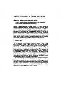
Figure 1. Ecore class diagram of the generic multi-model. Abstract types are written italic, interfaces are marked with an I-symbol.
IV. The Generic Multi-Model A. Approach Prior a further detailed discussion of the authors´ approach, relevant terms have to be defined. The following definitions apply in the former described scope of the multi-model context: Definition (Elementary Model, EM): An Elementary Model is an exchangeable instance of a data model with a delimited domain and an appointed semantic. That means an Elementary Model does not require a corresponding explicit schema - e.g. XML-documents without XSD - but the semantic of the data must be known. Definition (Link Model): A Link Model is a serializable instance of a data model with a schema that stores references between elements of different Elementary Models. Definition (Multi-Model): A Multi-Model is a serializable composite of a set of Elementary Models E and a possibly empty set of Link Models having elements of E as subject. Due to the general acceptance in software development as well as to the existence of a comprehensive tool support, the authors decided to create the multi-model schema under consideration as an object oriented model. Therefore requirement 7 is native met, because the system is extensible (e.g. by sub-classing) as well as formally adaptable due to the existence of a schema at which a converter from an
individual multi-model system may work for a complete mapping. B. Multi-Model Schema The model was defined by the use of the Ecore metamodel provided by the Eclipse Modeling Framework (EMF) [16]. Using that tool, a standard Java implementation as well as a corresponding XML serialization were generated directly out of the model - addressing requirements 8 and 9. The resulting class diagram is shown in Fig. 1. The hereby introduced classes describe the realm of linked EMs regardless of the inherent domain of an EM instance (requirement 1). In fulfillment of requirement 2, concrete classes are provided for the creation of multimodels without need for sub-classing - as well as a metadata mechanism that allows most of the objects to carry yet unspecified data by key-value-pairs. Requirement 3 is addressed by two subclasses of ElementaryModel. EmbeddedElementaryModel allows embedding of the original domain model as a ByteArray into the multi-model. As this amount of data can be large e.g. several 100 MByte are not unusual for IFC files - the class UriElementaryModel enables referencing the model’s physical location by an URI instead. Requirements 4 and 5 are met by the explicit externalization of references between EMs. As most of the existing
construction information models have identifiers for their elements, the authors chose an ID-based linking. That way links can be held outside of the domain models. Here the class LinkModel represents the idea of task-specific linking - each instance stands for a distinct combination of some of the EMs. Each contained link is expressed by an instance of class Link where the n-arity of requirement 6 as well as the ability to have a higher cardinality are implemented by a collection of contained LinkedElements. Each instance of that class represents one EM-element by using its ID in the attribute elementID. For further convenience the class LinkModel provides a reference to ElementaryModel having all the EMs which are subjects of the contained Links. Therefore an user or application does not have to inspect all LinkedElement instances to discover whether a LinkModel is relevant to it. C. Constraints Additionally to the Ecore-model of the generic multimodel there are constraints which cannot be expressed by the graphical notation. All constraints described in the following apply for the same MultiModel-object: mm ∈ M M | MM are the instances of class MultiModel
1) All referenced ElementaryModels of a LinkModel must be unique: lm ∈ mm.linkM odels em1 , em2 ∈ lm.linkedM odels ∀em1 , em2 : em1 ̸= em2
2) All referenced ElementaryModels of a LinkModel must be contained by the MultiModel: ∀em1 : em1 ∈ mm.elementaryM odels
3) The referenced elements of the ElementaryModels of all LinkedElements of a Link must be unique: l ∈ lm.links le1 , le2 ∈ l.linkedElements ∀le1 , le2 : le1 .elementaryM odel ̸= le2 .elementaryM odel ∨ le1 .elementID ̸= le2 .elementID
4) The referenced ElementaryModel of a LinkedElement must be referenced by the containing LinkModel too: ∀le1 : le1 .elementaryM odel ∈ lm.linkedM odels
5) The keys of all MetaDataEntrys of an Annotatable must be unique: a ∈ A | A are the instances of class Annotatable mde1 , mde2 ∈ a.metaDataEntries ∀mde1 , mde2 : mde1 .key ̸= mde2 .key
D. Methods for Identifying Elements without ID As the authors´ approach strongly relies on the existence of IDs for the EM elements, fallback strategies are necessary in case they are absent. This may happen e.g. due to a faulty model serialization or by a schema lacking ID-attributes for some or all elements at all. Although it violates requirement 4, a multi-model implementation could try to fix missing IDs in an EM. It could (1) generate and set IDs according to the EM´s directive. Then the implementation should mark the EM with the MetaData-key cib.model.generatedID and its mandatory value TRUE . (2) In case no ID-attributes are
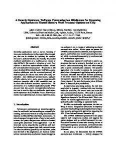
Figure 2.
Link Type Hierarchy
intended, they could be added if this is supported by the serialization format, e.g. XML or JSON. Implementations should choose a unique but representative attribute name and propagate it as value for the EM´s MetaData-key: cib.model.artificialIDAttribute. Non-manipulative methods could (3) use primary keys of models stored in relational databases as native ID-substitute. The primary key is used as value for the attribute elementID; the MetaDatakeys cib.linkedElement.artificialID.rdb.pk.{db | schema | table | column} may be used to specify the corresponding element location. The following methods may not provide unique results, are domain specific and rely on particular conventions between sender and receiver. Therefore appropriate MetaData has to be defined by a specification developer. IDs could be represented by (4) feature paths (e.g. Root->Building->Roof for a building element), (5) collection indices (e.g. Root>Building(1)->Wall(17) ) or (6) by a query (e.g. building.name=‘garage‘ && wall.height > 3.5 ). E. Operational Link Type Specifications The specifications of link model and links introduced in the previous sections created the necessary prerequisite for connecting elements of EMs with each other. But initially no general statement could be derived as to the meaning of these connections. So an interpretation of the relations between various objects forming the basis for validity tests and inference technologies is difficult to achieve. In this paragraph with the definition of link types a generalized realization concept is formulated to add structural as well as semantic information with the aim of improving coherence of models. Here, instead of a prescriptive approach a purely descriptive one is preferred to preserve the generic character of the multi model. Thus, the following specification of link types is merely to be understood as optional and not as obligatory, so that the user is not restricted when defining links. The core structure of the link type concept builds a top down design defining link types at varying degrees of detail
and abstraction. In this concept four abstraction layers for link type definition can be distinguished (see Fig. 2): • General link types, • Model specific link types, • Class specific link types and • Object specific link types. General link types form the highest level of abstraction. They offer the user the opportunity to define link types model-, class- and object-independent. On lower layers new link types can be added or link types with a higher degree of abstraction can be specialized using layer specific entities (model type, model instance, class, object). To avoid ambiguity and inconsistency in the meaning of link types by specializing them on lower layers, priorities can be established corresponding to reverse order of degree of abstraction. This priority concept follows the concept of inheritance and method overriding known from object oriented programming languages. Link type definitions can be formulated on each abstraction layer with a unique syntax and semantics. The focus of this paper is on the formal description of structure which is supplemented with an intuitive and informal semantics. For describing the structure of link types formal and in a general manner the Backus-Naur Form (BNF) is preferred. At first, to achieve such a general description of structure mathematical properties of relations, which are relevant for the use of a multi-model in civil engineering, are identified and analyzed with regard to realization in BNF: 1) Arity of relations: For link type definition n-ary relations are reduced - without losing any information - to binary representation:R(x, y, z) → R(R(x, y), z) or R(x, R(y, z)) or R(R(x, z), y)
2) Direction of relations: The direction of relations is encoded via the order of the involved entities. 3) Cardinality: Cardinality is encoded as prefixes, which are prepended to all entities. 4) Identifier for link types: Identifier are Strings and part of the relation properties. They are obligatory. 5) Symmetry, transitivity: Symmetry and transitivity are also relation properties. They are added at the end. Next to the formalization of mathematical properties the possibility is given to specify inherence between link types by encoding the parent link types as relation properties. This results in the following BNF representation:
objectN ame ::= (string corresponding to an object name) identif ier ::= (string starting with a letter)
The description of link types is realized by the two strings key and value of the class MetaDataEntry. With the key definition cib.link.type the link type specification in BNF can take place. From the technical point of view general link types can be used to annotate a MultiModel instance, model and class specific link types can be applied on LinkModel instances and object specific link types can be specified for Link instances. F. Discussion The presented data schema is only one of many potential solutions to the given problem. However a development of an optimized schema according to further formal quality criteria is out of the scope of this work. The fulfillment of the given requirements have been validated informally by usage of the prototype implementation which is described in the following section. V. Application and Adoption Examples A. M2A2 The prototypical implementation of the proposed data schema and its constraints was done within the MultiModel Assembly and Analyzing Platform (M2A2) at the Institute of Construction Informatics at the Dresden University of Technology. This application is a further development of the framework described in [2] and intended to create and inspect instances of the generic multi-model. It provides a graphical user interface for editing the elements of a multi-model. It is currently used in the HESMOSproject4 for investigations of multi-model arrangements in the domain of energy efficiency and building automation systems. Fig. 3 shows a screen shot of the application. B. Mefisto-Platform and Container
Multi-models are widely used in the MEFISTOproject5 . A lean central registry is used to find multimodels with specific properties of granularity (e.g. the level of detail of a building model´s geometry), the completeness of the linking process or the purpose of linked elements (e.g. for bidding). Therefore particular MetaData specifications are under development, describing common synLinkT ypeDef ::= prop(card(Entity), card(Entity)) | qualities of the 7 defined EM-types. Multi-models are prop(card(LinkT ype), card(LinkT ype)) | prop(card(Entity), prop(card(LinkT ype), card(LinkT ype))) | exchanged by a special Mefisto-container which is a comprop(prop(card(LinkT ype), card(LinkT ype)), card(Entity)) pressed archive of several data files and folders. Adapters bridge the gap to the here presented generic approach card ::= 0 | (natural numbers) | ∗ prop ::= identif ier [({identif ier} , mathP rop)] | and its M2A2 implementation. As only binary and singlemathP rop ::= symmetric | transitive valued relations are structurally possible there, arity and Entity ::= identif ier | cardinality of relations have to be defined by additional modelT ype[classN ame[objectN ame]] | MetaData. modelN ame[classN ame[objectN ame]] modelT ype ::= (string corresponding to a model type) modelN ame ::= (string corresponding to a model name) classN ame ::= (string corresponding to a class name)
4 http://hesmos.eu/ 5 http://www.mefisto-bau.de/
Figure 3. Screen shot of the M2A2 application showing the representation of a multi-model´s elements: all ElementaryModels (1) and all LinkModels (2), all referenced linkedModels (3) and all Links (4) of the selected LinkModel and all LinkedElements (5) of the selected Link. All MetaDataEntries of a selected Annotatable are shown in view 6. Extensions may place user interface elements specific to the type of the selected EM in area 7, e.g. showing an IFC model in a 3D-viewer (8).
VI. Summary and Future Prospects The proposed schema for multi-models enables links between domain models to be made explicit, exposed and neutrally exchanged beside the models. Optional predefined meta-data support further structural and semantic description to avoid wrong interpretation as far as possible. The system is generic and extensible but also ready for use out of the box. This allows the future creation of multimodel tools working on a common base, including (semi-) automated linking, multi-model filters and visualizations. As the focus of this approach is on data exchange, the responsibility for multi-model interpretation and domain semantics is deferred to specification developers and implementing applications. Further research is necessary to provide semantic safe model linking and to minimize the amount of manual specification. Acknowledgment The research work presented in this paper is part of the project ICT Platform for Holistic Energy Efficiency Simulation and Lifecycle Management of Public Use Facilities (HESMOS) which is funded by the Seventh Framework Program of the European Community under EC Grant Agreement Number 26088 and by the project partners. This support is gratefully acknowledged. References [1] G. Aouad, A. Lee, and S. Wu, Eds., Constructing the future: nD modelling. Taylor & Francis, London, UK, 2007. [2] S. Fuchs, P. Katranuschkov, and R. J. Scherer, “A framework for multi-model collaboration and visualisation,” in Proc. ECPPM 2010. Taylor & Francis, 2010, pp. 115–120.
[3] R. J. Scherer, S.-E. Schapke, and P. Katranuschkov, “Ontologybased ict-platform for management, simulation and decision making in large scale construction projects,” in Computing in Civil and Building Engineering, Proceedings of the International Conference, W. Tizani, Ed. Nottingham University Press, 2010, pp. 201–206. [4] R. J. Scherer, “Mefisto - cooperative use of multi-model information for controling, simulation and leading of construction projects (in german: Mefisto - partnerschaftliche nutzung von multi-modellinformationen zur steuerung, simulation und f¨ uhrung von bauprojekten),” in MEFISTO: Management F¨ uhrung - Information - Simulation im Bauwesen, R. Scherer and S.-E. Schapke, Eds., 2010, pp. 9–36. [5] D. Muntzinger and S. Fuchs, “Software applications for integration and evaluation of combinable domain models (in german: Softwareanwendungen f¨ ur die integration und auswertung kombinierbarer fachmodelle),” in MEFISTO: Management F¨ uhrung - Information - Simulation im Bauwesen, R. Scherer and S.-E. Schapke, Eds., 2010, pp. 117–12. [6] P. Katranuschkov, M. Weise, R. Windisch, S. Fuchs, and R. J. Scherer, “Bim-based generation of multi-model views,” in Proc. CIB W78 2010, 2010. [7] H. Willenbacher, “Interactive link-based building modelling as integration platform for building life cycle (in german: Interaktive verkn¨ upfungsbasierte bauwerksmodellierung als integrationsplattform f¨ ur den bauwerkslebenszyklus),” Ph.D. dissertation, Bauhaus-Universit¨ at Weimar, 6 2002. [8] H. Willenbacher and R. H¨ ubler, “Intelligent link-management for the support of integration in building life cycle,” in Proc. of International Conference on Computing in Civil and Building Engineering 2004, 2004. [9] J. Ye, “Integrating data models, analysis and multidimensional visualizations : a unified construction project management arena,” Ph.D. dissertation, University of British Columbia, 11 2009. [10] K. Wender, “The virtual building as information environment for planning in existend context to organize and structure a digital building documentation (in german: Das virtuelle bauwerk als informationsumgebung f¨ ur die planung im bestand zur organisation und strukturierung einer digitalen bauwerksdokumentation),” Ph.D. dissertation, Bauhaus-Universit¨ at Weimar, 5 2009. [11] J. Tulke, “Collaborative time scheduling based on building information models (in german: Kollaborative terminplanung auf basis von bauwerksinformationsmodellen),” Ph.D. dissertation, Bauhaus-Universit¨ at Weimar, 7 2010. [12] J.-A. Goulet, P. Kripakaran, and I. F. C. Smith, “Multimodel structural performance monitoring,” Journal of Structural Engineering, vol. 136, no. 10, pp. 1309–1318, 2010. [Online]. Available: http://link.aip.org/link/?QST/136/1309/1 [13] I. F. C. Smith and S. Saitta, “Improving knowledge of structural system behavior through multiple models,” Journal of Structural Engineering, vol. 134, no. 4, pp. 553–561, 2008. [Online]. Available: http://link.aip.org/link/?QST/134/553/1 [14] I. F. Smith, “Multiple-Model Structural Identification,” in Encyclopedia of Structural Health Monitoring, C. Boller, F. Chang, and Y. Fujino, Eds. Chichester, UK: Wiley, 2009, pp. 2199– 2208. [15] T. Denton, E. Jones, S. Srinivasan, K. Owens, and R. W. Buskens, “Naomi — an experimental platform for multi—modeling,” in Proceedings of the 11th international conference on Model Driven Engineering Languages and Systems, ser. MoDELS ’08. Berlin, Heidelberg: Springer-Verlag, 2008, pp. 143–157. [Online]. Available: http://dx.doi.org/10.1007/978-3-540-87875-9 10 [16] D. Steinberg, F. Budinsky, M. Paternostro, and E. Merks, EMF: Eclipse Modeling Framework, 2nd ed. Addison-Wesley Professional, December 2008.