Model Driven Engineering, Formal Methods, System to Software Engineering, ... system/software engineering process for complex and critical space systems.
ESA / Astrium Space Transportation / Esterel Technologies / IRIT / Altran Praxis / Verimag
Formal Model Driven Engineering for Space Onboard Software Eric Conquet1, François-Xavier Dormoy2, Iulia Dragomir3, Susanne Graf4, David Lesens5, Piotr Nienaltowski6, Iulian Ober3 1
ESA, 2Esterel Technologies, 3IRIT, 4VERIMAG, 5Astrium Space Transportation, 6Altran Praxis
Keywords:
1
Model Driven Engineering, Formal Methods, System to Software Engineering, Model Transformation, SPARK
Introduction
One of the major sources of errors in the development of real time critical embedded software is the misinterpretation of system requirements allocated to the software. These misunderstandings between the system team and the software team may have several sources, but are very often due to the following causes: o Use of ambiguous means to describe the system requirements and the software implementation, leading to different interpretations by the system designers, the software developers and the reviewers. o Insufficient knowledge by the software team of the formalisms and jargons used by the system team, leading to the development of software that does not satisfy the system requirements. o Insufficient knowledge by the system team of the formalisms and jargons used by the software team, leading to inefficient reviews of the software specification and code by the system team. The errors potentially introduced during the development are then generally discovered very late by very costly test processes. From September 2004 to December 2007, the European Space Agency (ESA) led the ASSERT project [1] of the FP6, with the objective of defining a complete system/software engineering process for complex and critical space systems. The ASSERT development process is now supported by a set of tools called TASTE [4]. The main scope of the ASSERT project was the management of non functional requirements, from the capture of system requirements to the automatic generation of code. This paper presents the “Full Model Driven Development for On-Board Software” project (acronym FMDE), aiming at completing the ASSERT process by the functional approach. It has been co-funded by ESA, Astrium Space Transportation, Esterel Technologies, IRIT (Institut de Recherche en Informatique de Toulouse), Altran Praxis and Verimag.
2
The FMDE project approach
The FMDE project is based on the following three principles: o Formalisation of each step of the development by safe and non-ambiguous languages. For several years, Model Driven Engineering has reduced the risks of requirement misinterpretation by facilitating the communication between the system and software teams. The following languages have been selected: • SysML for the system design. SysML is a graphical modelling language adapted to system engineering and increasingly used in the industry. Astrium Space Transportation has for instance deployed SysML for the capture of the system requirements of the new version of the Ariane 5 launcher. • SCADE Suite for the software design. SCADE is a graphical modelling language mixing automata and data flow views. SCADE Suite is commercialised by Esterel Technologies. • Ada for the coding. Ada is a programming language targeting the development of critical real time software. Even though Ada is not graphical, it has been designed to be safe and easily understandable (it avoids shortcuts and favours syntax close to natural English). o Use of formal techniques allowing greatly increased confidence in the system compared to a more traditional approach relying only on tests and informal documents written in a natural language. The first objective of a formal language is to suppress all potential ambiguities by defining a formal unambiguous semantics. Its second objective is to provide proof techniques that increase confidence in the system and software and decrease the testing effort. • SCADE Suite is already a formal language for which proof techniques are commercialised by Esterel Technologies. ERTS 2012
1 / 10
ESA / Astrium Space Transportation / Esterel Technologies / IRIT / Altran Praxis / Verimag •
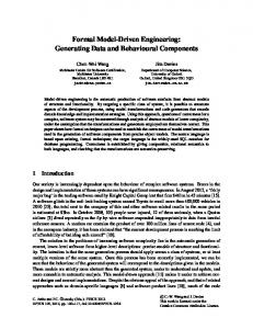
The SysML standard is not always precise enough and leaves an important part of its semantics undefined. The FMDE project has thus adapted the OMEGA profile (previously available for UML) to the SysML language in order to suppress any ambiguity in the system models and to allow formal proof. This requires the addition of new modelling constructs and the definition of a set of rules to clarify some semantics variation points of SysML (e.g. forbidding of bidirectional ports, typing of connectors, port behaviours). The behaviour of the system can be modelled in OMEGA SysML by state machines and operations invoking actions. The OMEGA profile also allows the description of timed behaviours and observers to formalise the requirements and dynamic properties of the system. The OMEGA SysML profile is supported by a toolbox called IFx-OMEGA [11]. IFx-OMEGA provides some features for the simulation and verification of OMEGA SysML models, relying on a model transformation from OMEGA models to the IF language [10]. • Finally, even though Ada is well adapted for writing critical software, it still contains some ambiguous or dangerous constructs. The FMDE project has thus proposed to use the SPARK language [13]. SPARK is specifically designed to support the development of software for systems where the correct operation of the software is essential for the safety or security of the system. The language is based on a core subset of Ada and augmented with annotations which describe and support the programming-by-contract approach. The SPARK Toolset offers static verification that is unrivalled in terms of its soundness, low false-alarm rate, depth and efficiency. The tools also generate evidence for correctness that can be used to build an assurance case to satisfy the requirements of industry regulators and certification bodies. The language and tools have been successfully used in the development of many high-integrity systems in various domains: air traffic control, on-board aircraft systems, control systems, rail systems, as well as security applications. o Optimisation of the successive refinement steps (from the system design to the software design and then from the software design to the implementation code) thanks to model transformation techniques: • Automatic generation of a skeleton of the software model in SCADE Suite from the system model in SysML. This objective has been achieved by integrating SCADE Suite and the Papyrus SysML modeller through the new SCADE System Designer tool. Having two interconnected meta-models allows consistency to be kept between the system model and the software model. A model transformation creates a SCADE node with the same interface as a system component (modelled by a SysML block). • Automatic generation of SPARK code from the software model in SCADE Suite by a tool certifiable to DO178B level A. The combination of SPARK and SCADE allows the verification of the correct integration between manual and automatically generated code, the verification of absence of runtime errors and the verification of functional properties. In order to get maximum benefit from this SPARK/SCADE combination, the SCADE language has been enhanced with new basic types (int8, int16, int32, int64, uint8, uint16, uint32, uint64, float32, float64), better management of imported types and definition of ranges (minimal and maximal bounds of a type). The Figure 1 summarizes the process proposed in the FMDE project. System design Papyrus or Rhapsody modeller with Omega profile
Formal proof
Model transformation & refinement Software specification Formal proof
Generated
+
Manual
Code generator Implementation code Formal proof
Generated
+
Manual
Figure 1: An engineering process based on models, formal methods and model transformation
ERTS 2012
2 / 10
ESA / Astrium Space Transportation / Esterel Technologies / IRIT / Altran Praxis / Verimag
3
Capture of the system design with SysML and the OMEGA profile
OMEGA is a SysML profile which defines an unambiguous operational semantics for a subset of SysML. It focuses on the architectural description of systems by means of block diagrams and on the behaviour associated with blocks, in particular block state machines. The SysML profile is built upon OMEGA UML, a UML profile for the specification of real time embedded software, but extends its spectrum beyond software to system design. The benefit of the precise operational semantics is that the associated IFx-OMEGA platform [11], which provides simulation and model checking tools, can be used to validate OMEGA SysML models.
3.1
Modelling elements of OMEGA SysML
The architecture of an OMEGA model is expressed through Block Definition Diagrams (BDDs). As in standard SysML [12], it captures the definition of blocks in terms of properties and operations, and relationships such as associations, generalizations and dependencies. The hierarchical structure of blocks, communication ports and connectors is specified through Internal Block Diagrams (IBDs). The profile imposes a few restrictions on the use of certain model elements, either in order to comply with the communication model adopted by its operational semantics which relies on asynchronous message passing, or in order to clarify ambiguities related to IBDs. For example, the semantics is restricted to standard ports only, while flow ports can be present in the model but are ignored. We summarize below some of the OMEGA concepts intended to clarify the semantics of IBDs: o Dynamic typing of connectors: since several connectors may be connected to one port in SysML, it is important to define the rules that state which requests are transferred through which connectors. OMEGA introduces the notion of a set of transported interfaces which is computed as the intersection of the sets of provided/required interfaces at the two ends of the connector. The sets of transported interfaces connected to a port have to be pairwise disjoint to avoid ambiguities, unless the port has a user-specified behaviour. Each connector has to contain at least one interface. o Port and connector direction: in SysML ports are bidirectional, which is error-prone and complicates the type checking of certain actions operating on ports. The adopted solution is to forbid bidirectional ports; any bidirectional communication has to take place through two separate unidirectional ports. The direction of a port is given by its interface – provided or required – and the direction compatibility rules for connectors, which are informally specified in the SysML standard [12], are formalised. Nested connector ends, allowed by the standard, are not allowed because they cause encapsulation problems. o Default port behaviour: the behaviour of a port is fully defined by rules for deriving its state machine from its provided/required interfaces and from the set of connectors bound to it. The concepts and rules mentioned above result in a strongly typed language which encourages rigorous system engineering. The behaviour of a system is captured in OMEGA SysML mainly by state machines, attached either to blocks or (less usually) to port types. Like in the standard, another possibility, reminiscent of UML, is to define block operations, which can then be invoked asynchronously. While the profile does not support activity diagrams for specifying complex actions, it does support a textual action language which covers most of the basic actions defined in the standard (signal sending, operation calls, expression evaluation, variable assignments, block creation, etc.) as well as control flow structuring statements.
3.2
Static and operational semantics
The static semantics of the profile is defined by well-formedness rules formalised in OCL. These rules concern the strong typing principles and the restrictions relative to the structure of IBDs mentioned in the previous section. Further details on the formalisation and the rationale can be found in [7]. One of the first benefits of using the OMEGA profile is the tool support helping system engineers obtain statically valid and well-defined models. For the operational semantics, OMEGA relies on an asynchronous timed execution model. Each basic block with behaviour is considered as a timed automaton, potentially executing in parallel with other blocks and communicating via asynchronous signals or asynchronous operation calls. In order to offer a mechanism for controlling the granularity of concurrency, the semantics takes into account the isActive attribute that SysML blocks inherit from UML classes (some additional constraints ensure that the active/passive status is compatible with the block hierarchy, as described in [6]). Based on this attribute, the set of blocks at runtime is partitioned into parallel activity groups. Each activity group reacts to external stimuli (asynchronous signals and calls) in atomic run-to-completion steps. This execution model has been defined first for OMEGA UML and details can be found in [6]. The model time base can be either discrete or dense and it is specified by the user when simulation or model-checking is performed. Model time is controlled using the primitives of timed automata with urgency [3]: clocks, timed guards and ERTS 2012
3 / 10
ESA / Astrium Space Transportation / Esterel Technologies / IRIT / Altran Praxis / Verimag transition urgency annotations, which are stereotypes used to control how logical time can progress depending on the transitions that are fireable in a certain state. Time progress can thus be disabled (when at least one urgent transition is fireable), enabled but bounded (when there is no urgent transition but there is at least one delayable transition), or enabled and unbounded. Another extension with respect to standard SysML is the introduction of observers, used in order to formalise requirements and dynamic properties of a system (more specifically, timed safety properties). Observers are blocks with a special stereotype, and which define a state machine reacting to various types of events happening anywhere in the system, and detecting and rejecting the behaviours of the system that do not satisfy the requirement.
3.3
The IFx-OMEGA platform
The SysML profile is implemented by the IFx-OMEGA platform, consisting of static checking, compiling, simulation and model-checking tools. The tools rely on the translation of the relevant parts of a model to the input language of the IFx toolset [11], which is based on asynchronous communicating timed automata. The toolset handles SysML models in XMI 2.1, edited by an editor compliant with Eclipse EMF such as IBM Rhapsody or Papyrus MDT. The compiler verifies the set of well-formedness rule described above, and then generates an IF model which can be further simplified through static analysis techniques like dead code/variable elimination or slicing. The model-checking step consists in computing the product state space of the relevant part of the model and a set of observers while searching for the absence of error states. As usual in enumerative model checkers, this search can be parameterized, and techniques like partial order reduction [5] can be used to minimize the search space. Generated error scenarios can be played and debugged in the simulator. The SysML version of IFx-OMEGA builds upon existing components for OMEGA UML which have already been successfully applied to industrial case studies like the Ariane 5 flight program [9].
4
From the system model to the software model with SCADE System Designer
The FMDE project approach is relying on formalisation of each step of the development by safe and non-ambiguous languages. SysML with OMEGA is chosen at System Level, SCADE Suite has been selected for the software part and SPARK for the coding part. This section describes the first two steps of the process: system design and software specification (see Figure 1). Besides bridging these steps, Esterel technologies provides a single framework to tightly integrate Papyrus MDT used for System engineering and SCADE for software engineering. SCADE System is a result of joint laboratory between French Atomic Energy Commission (CEA List) and Esterel Technologies to provide an open source (EPL), professional and well supported product for embedded systems modelling based on SysML standard and the Papyrus MDT open source technology.
4.1
SCADE System architecture
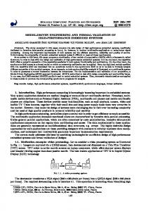
SCADE System is much more than just another SysML tool: it provides a powerful model based environment that allows system engineers to capture, in an industrial way, the functional decomposition, architecture, allocation of functions to components and description of I/O and signals, using a subset of SysML. In order to perform a tight integration, a single framework is embedding both Papyrus MDT and SCADE Suite. SCADE Studio framework has been chosen and a Studio-Eclipse Glue module has been developed to integrate Papyrus MDT in SCADE framework as explain is the figure below:
Figure 2: Architecture of SCADE System
ERTS 2012
4 / 10
ESA / Astrium Space Transportation / Esterel Technologies / IRIT / Altran Praxis / Verimag This architecture brings many benefits: o Papyrus MDT components shared with SCADE System Designer are Open source (EPL license). o SysML and SCADE Suite in the same framework with two interconnected meta-models allow managing consistencies and reconciliation between the models. o SCADE Framework is now interoperable, extensible with other Papyrus MDT components and opened to plug in other Eclipse based tools. o A SysML API (Java and TCL) is provided for data extraction, import and modification. o Unified look and feel with SCADE. o Intuitive navigation between system architecture and software. o A common traceability tools can be used for both (RM Gateway). o A common document generation module can be used for both models. o A common configuration management policy and tooling solution can be used for both models.
4.2
Synchronising system and software design
As stated before, the main focus of our work is twofold: hide and avoid as much as possible cumbersome SysML features to provide a tool for system engineers and not SysML “geeks”, and integrate in a single framework system tools and software tools in order to make a consistent and complete model based design environment for both system and software design phases. The following features have been developed: o Identify the software components at system level. A special tag for SCADE Suite and SCADE Display is added to automate subsequent synchronisation. o Create (initialize) a SCADE Suite project from System design (types, blocks, inputs/outputs). The tag provided is used to select what needs to be translated. o On request, identify changes in a software or system part that could be applied to the other part (merge, merge between formalism). To support that feature, which will be available in SCADE System 2.0, transformation to neutral format is done. o Navigation features from System design to software-related design are provided.
5
From software model to SPARK code
This section is about bridging the last two steps of the process: software design and coding. These steps are coupled through automatic code generation from a formal (synchronous) model, which allows generating a fully certifiable code from the software design. This method and technologies have been used for more than 10 years now and are now fully accepted by certification authorities as a safe way to develop code. The added value of the work done in FMDE is to generate SPARK / ADA code (instead of C code) that is amenable to formal proof.
5.1
SCADE extension
The need to generate SPARK code has had some impact on the SCADE language. This section represents the main extensions introduced to take full advantage of the new target language. 5.1.1
Numeric types
Hierarchy of numeric types We enrich the existing hierarchy with the following built-in data types: int, int8, int16, int32, int64, uint8, uint16, numeric, real, float32, numeric, floating, float64
uint32,
uint64,
integer,
Different numeric types are incompatible, e.g. you cannot add a flow of type int8 and a flow of type int32. For each built-in type, there exists a cast operator with the same name as the type: int8, int16, int32, etc. The “prefix” versions of these operators are also available: int8$, int16$, int32$, etc. Numeric constraints on polymorphic operators Like numeric, the integer and floating keywords cannot be directly involved in type expressions, but they can be used to specify numeric constraints in order to restrict the polymorphism of user-defined operators. For example: function imported N1 (x:'t) returns (y:'t) where 't numeric;
may be instantiated by any numeric type. ERTS 2012
5 / 10
ESA / Astrium Space Transportation / Esterel Technologies / IRIT / Altran Praxis / Verimag function imported N2 (x:'t) returns (y:'t) where 't integer ;
may be instantiated by any subtype of integer (in the hierarchy of numeric types). function imported N3 (x:'t) returns (y:'t) where 't floating ;
may be instantiated by any subtype of floating. Numeric imported types In addition to the implementation of new built-in types, there is now a mechanism to extend the hierarchy of numeric types with user-defined imported types: type imported T1 is numeric;
defines a new numeric type (which is not a subtype of integer or floating) type imported T2 is integer ;
defines a new subtype of integer (like int8/int16/etc.) type imported T3 is floating ;
defines a new subtype of floating (like float32/float64/etc.) Numeric imported types are incompatible with each other and with other built-in types. Type conversion for numeric types We introduce a generic cast operator (:) for conversions from/to numeric types (including built-in, imported and polymorphic ones), e.g.: type imported Timp is numeric; function F (x1: int8 ; x2:'t) returns (y1: float32 ; y2:'t; y3: Timp) where 't floating let y1 = (x1: float32); -- equivalent to float32 (x1); y2 = (x1:'t); y3 = (x2: Timp); tel
Note: this new construct subsumes the old syntax (INT:'t) which may still be used in order to express literals of polymorphic numeric types. All floating to integer casts now use the “truncation” semantics. In C, this was already the default behaviour. In the generated SPARK code, we make use of the 'Truncation attribute before converting the floating value. 5.1.2
Ranges on numeric types
Ranges are very important in SPARK and represent a key benefit that needed to be added in SCADE. This section presents the introduction of ranges in the SCADE language. Range annotations We provide the following syntax for range annotations: ::= ... | { .. }
It is possible to annotate any numeric type (including built-in, imported and polymorphic ones), e.g.: int8 {0 .. 100} 't { -10 .. 10} -- where 't integer T_imp { -3.14 .. 3.14 } -- T_imp is floating
Other types (such as enums, for instance) cannot receive a range annotation in SCADE. We also provide a new syntax “fe1 ..^ e2g” which is equivalent to “e1 .. e1+e2-1”. This works for both range annotations and array slices: type T = int { -10 ..^ 100}; -- equivalent to: type T = int {-10 .. 89}; y = x[0 ..^ 10]; -- equivalent to: y = x[0 .. 9];
Range bounds The subset of expressions that can be used to express a range bound includes that of size expressions, but is not limited to integer flows.
ERTS 2012
6 / 10
ESA / Astrium Space Transportation / Esterel Technologies / IRIT / Altran Praxis / Verimag Moreover, the type of each range bound must be compatible with the numeric type receiving the range annotation. However, the “compatibility” depends on whether this is a (static) integer range or not: o If both bounds are static, then the only constraint for the underlying type is to be integer o Else, the type of each bound must exactly match the underlying type. For instance: int32 {0 .. 10} -- is correct real32 {-3.14 .. 3.14} -- is correct int {int8 (0) .. int16 (10)} -- is correct (bounds are static and -- underlying type is integer) int {0.0 .. 3.14} -- is incorrect -- (bounds are floating and underlying type is integer)
Note: the aforesaid ..^ notation is less permissive: o It can only be used to specify integer ranges, e.g. {3:14 ..^ 10} will be rejected o The “length” value (such as N in {x ..^ N}) must be strictly positive, to denote a valid range. 5.1.3
Generated code for Ada target
Several improvements have been made in the SCADE Code generator to better support SPARK. For instance, for packages we tried to ensure a one-to-one correspondence with the package hierarchy defined in the SCADE model. For example, the following SCADE code: package MyLib function F (x : int ) returns (y : int ) y = 2*x + 1; function G (x : int ) returns (y : int ) y = if x > 100 then 1 else 10; end;
will give rise to the following SPARK / Ada code: with Kcg_Config ; use type Kcg_Config . Kcg_int ; package body MyLib is function F(x : Kcg_Config . Kcg_int ) return Kcg_Config . Kcg_int is begin y := 2 * x + 1; return y; end F; function G (x : Kcg_Config . Kcg_int ) return Kcg_Config . Kcg_int is begin if (x > 100) then y := 1; else y := 10; end if ; return y; end G; end MyLib ;
6
Formalisation and proof of the implementation code with SPARK
The SPARK language and tools have been specifically designed to support the development of software for highintegrity systems where the correctness of software is essential to ensure the safety or security of the entire system. SPARK is based on a core subset of Ada and enriched with annotations that support the programming-by-contract approach [2]. The SPARK Pro Toolset offers static verification with unparalleled soundness, depth, efficiency and low false-alarm rate. SPARK relies on the following principles that make it particularly well suited for the software design and development method proposed by the FMDE project: o Logical soundness and language security. A key property of SPARK is its lack of ambiguity: the language rules and annotations ensure that a program text can only be interpreted in one way by all standard Ada compilers. Semantic ambiguities present in other languages, for example the reliance on a given order of subexpression evaluation or parameter-passing semantics, do not exist in SPARK.
ERTS 2012
7 / 10
ESA / Astrium Space Transportation / Esterel Technologies / IRIT / Altran Praxis / Verimag o Simplicity. The language avoids syntactic and semantic complexity, which makes it easier to analyse formally, to read and to understand, especially for a human reader. The latter property is important even in systems where most (if not all) code is generated automatically from a SCADE model because it facilitates the understanding of the mapping between program constructs and elements of the model. This is important when generating various elements of certification evidence; for example, requirements tracing. o Expressive power. Despite the exclusion of non-deterministic constructs, SPARK retains all the important features of Ada that allow the construction of well-engineered programs for real time high-integrity systems. SPARK provides abstraction, modularity and encapsulation mechanisms. Hierarchies and single-level inheritance are both supported within the language through child packages and derived types. o Verifiability. SPARK annotations such as pre-conditions, post-conditions and loop invariants provide sufficient contextual information to allow verification of a program section with reference only to the specifications of the packages that the section relies on. This allows effective analysis of large systems in a modular and incremental manner. o Correspondence with Ada. All legal SPARK programs are also legal Ada programs. There are many benefits from sharing technology and general resources with an existing language that has been widely adopted in the high-integrity software industry. The logical soundness of SPARK means that programs can be compiled with any standard Ada compiler without the risk of altering the program semantics. The SPARK Pro Toolset can verify the correctness of programs by using rigorous mathematical analysis. All types of analysis supported by the tools — from data flow and information flow analysis, through proof of absence of run-time exceptions, to formal verification of correct functionality of the program against a specification — are fast: they are performed in polynomial time (there is a trade-off between speed and completeness: the analysis is fast but not every correct program can be proven). Data flow analysis ensures initialisation of all variables before their first use and detects any use (or non-use) of subprogram parameters that is incompatible with their stated mode (input, output or both). Information flow analysis checks the dependencies between the input and output parameters of subprograms, and the flow of information between a subprogram and other subprograms and modules it relies on. This type of analysis is a powerful tool for verifying safety properties such as non-interference between critical and non-critical data within a system. It also allows the detection of common coding errors such as infinite loops. The depth and complexity of formal proof can be adjusted to match the needs of a specific software system: the required integrity level and certification standard. In its simplest form, SPARK proof demonstrates the absence of run-time errors: it shows before the execution of a program that there will be no errors such as division by zero, buffer overflow or outof-range assignments to variables during the execution. The most complete and exhaustive form of proof is the proof of functional correctness of a program against a detailed formal specification. In most cases, a mixed approach is used, whereby a proof of absence of run-time exception is performed on the entire SPARK program and a full proof of specific functional properties is only performed on the most critical software components. This approach was used in the SGS case study within the FMDE project.
7
Validation of the FMDE approach on a case study
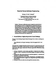
The FMDE approach, based on modelling, formal methods and model transformation has been validated on a case study based on the solar generation system (SGS) of the ATV (Automated Transfer Vehicle) program, a spacecraft developed by Astrium Space Transportation for ESA, aimed at supplying the International Space Station (ISS). Figure 3: ATV Jules Verne, during its rendezvous with the ISS, on the 3rd of April 2008
7.1
Work performed
The architecture of the system was first captured in OMEGA/SysML using requirement diagrams, use case diagrams, sequence diagrams, internal block diagrams and state machines. This model covers both the software part (mission management, procedure for the deployment of the solar wings and management of the fault tolerance) and the avionic part, composed of more than fifty pieces of equipment. The nominal behaviour, as well as the behaviour in case of failure of each piece of equipment, have been modelled to simulate the behaviour of the system in case of failure and to verify the requirement of one-fault tolerance. The IFx-OMEGA toolbox has been used to perform formal proofs of properties such as “the four solar wings of the ATV are deployed, even in case of failure”. ERTS 2012
8 / 10
ESA / Astrium Space Transportation / Esterel Technologies / IRIT / Altran Praxis / Verimag The architecture of the software model in SCADE Suite was automatically generated from the SysML model by SCADE System Designer. The SCADE model was then completed by the automata of the solar wing deployment. This model has been verified first by simulation, and then by formal proof (with properties such as “no command is sent to the solar wings when the ATV is attached to Ariane 5). The algorithms controlling the rotation of the solar wings (to maximise the energy received from the sun) have been developed in SPARK. The SPARK toolset has been used to formally and exhaustively prove the absence of run-time errors (97% of the Verification Conditions being automatically proved and 3% interactively proved by a theorem prover). Finally, the SPARK code automatically generated from the SCADE Suite model and the manual SPARK code have been integrated to produce the complete code.
7.2
Case study feedbacks
The use of Model Driven Engineering to develop a complex critical system has already been proved efficient before the FMDE project: o It decreases the number of misunderstanding during the development process. o It reduces the cost of verification and validation. o It improves the quality of the final system. One step further, the use of OMEGA and of the associated toolset IFx has allowed discovering residual errors in the SysML model that were not eliminated after the simulation phase. On some subsets of the model, the exhaustive formal proof has given evidence of the absence of unexpected behaviour. However, the overhead of developing a formal model compared to an informal model shall be taken into account. But at the end, the case study has shown that the total cost of the development, verification and validation is lower when using a formal model. As soon as the IFx toolset is industrialised, operational projects will benefit from it. The support for model transformation from SysML to SCADE provided by SCADE System Designer is not yet sufficiently mature. The case study has revealed that, in practice, there is no exact correspondence between the system architecture and the software architecture: some software-specific items are added during the refinement phase. This makes the design of such a tool not trivial. SCADE Suite is already in operational use in several industries. The FMDE study has confirmed the great interest of the SCADE approach: o Graphical development of the software architecture and of the automata, allowing an efficient review of the software code by system team o Formalisation, simulation and formal proof increasing the confidence in the software From the point of view of Astrium Space Transportation, the main drawback of SCADE Suite was the code generator limited to the production of C code. Indeed, the manual code completing the SCADE model and developed in the lowlevel C programming language counterbalanced the interest of SCADE. The generation of Ada code cancels this drawback. The generation of SPARK increases the confidence in the generated code. Finally, besides ensuring the correctness of software, the case study has practically shown that the use of SPARK eliminated common programming mistakes such as ineffective assignments, unused variables, infinite loops and stable expressions within loops in the hand-written code that implements various numerical algorithms, and helped to improve the structure of that code. There is additional effort involved in the initial phase of software development with SPARK. It may therefore be tempting to restrict the use of SPARK to the most critical software modules and use classical Ada for the remainder of the code. However, the initial effort associated with the use of SPARK is more than balanced out by the reduction in cost achieved by delivering better quality code through to the test and integration stages. To take full advantage of the FMDE approach, it is mandatory to ensure adequate training in SysML, Omega, SCADE, Ada and SPARK.
8
Conclusion and future work
The difficulties often met during the development of complex critical systems are well-known: late discovery of errors in the system architecture, incompatible interfaces of interacting components, ambiguities in the descriptions leading to misinterpretations by the development teams. The development process proposed by the FMDE project, integrated in the TASTE approach and supported by tools for verification and model transformation, avoids most of these risks. This is achieved through formalisation of each step of the development (to avoid ambiguities or misinterpretation), model transformation, early verification by simulation and formal proof. ERTS 2012
9 / 10
ESA / Astrium Space Transportation / Esterel Technologies / IRIT / Altran Praxis / Verimag We are convinced that this process and the associated tools will contribute to solving the software crisis in the space domain as well as in other domains of complex critical systems. To reach this goal, the partners of the FMDE project have already planned the following activities: o Extension of the Omega proof technology with a contract-based approach o Qualification of the KCG Ada code generator o Definition of Ada 2012 standard including some SPARK concepts Others activities may also be of interest: o Industrialisation of the Omega profile: IRIT and Verimag are exploring potential industrial partnerships in order to conduct this activity o Integration with TASTE In the space domain, the deployment of the technologies developed or assessed in the FMDE project is already in progress: o SysML is deployed on the Ariane 5 Mid-Life Evolution program. The SysML model is the unique reference for the electrical and software system: all the documentation (system design and software specification) is generated from this single source. The SysML model is validated by simulation. Guidelines and training are now available. The next step will be the use of formal verification. o SCADE is used on the Homer project with automatic C code generation. As for SysML, guidelines and training are available. The next step will be the generation of SPARK code. o The Avionic-X project, aiming at building a demonstrator of the avionic of future launchers, planes to use: • SysML and SCADE. • SPARK or Ada 2012.
9 [1] [2] [3] [4]
[5]
[6] [7]
[8] [9]
[10] [11] [12] [13]
References ASSERT project official website: www.assert-project.net J. Barnes. High integrity software: The SPARK approach to safety and integrity, Addison-Wesley, ISBN 0-32113616, April 2003 S. Bornot and J. Sifakis. An algebraic framework for urgency. Inf. Comput., 163(1):172–202, 2000. E. Conquet, M. Perrotin, P. Dissaux, T. Tsiodras, J. Hugues. “The TASTE Toolset: turning human designed heterogeneous systems into computer built homogeneous software”, Embedded Real Time Software and Systems (ERTSS’2010) P. Godefroid. Partial-Order Methods for the Verification of Concurrent Systems: An Approach to the StateExplosion Problem. J. van Leeuwen, J. Hartmanis, and G. Goos (Eds.). Volume 1032 of Lecture Notes in Computer Science, Springer, 1996. J. Hooman, H. Kugler, I. Ober, A. Votintseva, Y. Yushtein: Supporting UML-based development of embedded systems by formal techniques. Software and System Modeling 7(2): 131-155 (2008) I. Ober and I. Dragomir. Unambiguous UML composite structures: The OMEGA2 experience. In Ivana Cerna, Tibor Gyimothy, Juraj Hromkovic, Keith G. Jeffery, Rastislav Kralovic, Marko Vukolic, and Stefan Wolf, editors, SOFSEM, volume 6543 of Lecture Notes in Computer Science, pages 418–430. Springer, 2011. I. Ober, S. Graf, Y. Yushtein, and I. Ober. Timing analysis and validation with UML: the case of the embedded mars bus manager. Innovations in Systems and Software Engineering, 4(3):301–308, October 2008. I. Ober, S. Graf, and D. Lesens. Modeling and validation of a software architecture for the ariane-5 launcher. In R. Gorrieri and H. Wehrheim, editors, FMOODS, volume 4037 of Lecture Notes in Computer Science, pages 48–62. Springer, 2006. IF website: http://www-if.imag.fr/ IFx-OMEGA website: http://www.irit.fr/ifx OMG. Ob ject Management Group – Systems Modeling Language (SysML), v1.1. Available at http://www.omg.org/spec/SysML/1.1/, 2008. SPARK website: http://www.altran-praxis.com/spark.aspx
ERTS 2012
10 / 10