Formal Requirements-Based Programming for Complex Systems James L. Rash, Michael G. Hinchey NASA Goddard Space Flight Center Information Systems Division Greenbelt, MD 20771, USA {james.l.rash, michael.g.hinchey}@nasa.gov
Christopher A. Rouff SAIC Advanced Concepts Business Unit McLean, VA 22102, USA
[email protected]
Denis Graˇcanin Department of Computer Science Virginia Tech Blacksburg, VA 24061, USA
[email protected] Abstract
Computer science as a field has not yet produced a general method to mechanically transform complex computer system requirements into a provably equivalent implementation. Such a method would be one major step towards dealing with complexity in computing, yet it remains the elusive “holy grail” of system development. Currently available tools and methods that start with a formal model of a system and mechanically produce a provably equivalent implementation are valuable but not sufficient. The “gap” that such tools and methods leave unfilled is that the formal models cannot be proven to be equivalent to the system requirements as originated by the customer. For the classes of complex systems whose behavior can be described as a finite (but significant) set of scenarios, we offer a method for mechanically transforming requirements (expressed in restricted natural language, or appropriate graphical notations) into a provably equivalent formal model that can be used as the basis for code generation and other transformations. While other techniques are available, this method is unique in offering full mathematical tractability while using notations and techniques that are well known and well trusted. We illustrate the application of the method to an example procedure from the Hubble Robotic Servicing Mission currently under study and preliminary formulation at NASA Goddard Space Flight Center.
Key Words: Validation, verification, formal methods
1. Introduction The development of complex systems that have high levels of dependability and reliability requires the developer to represent the system as a formal model that can be proven to be correct. Through the use of currently available tools, the model can then be automatically transformed into code with minimal, or no, human intervention and with a correspondingly minimized chance of introducing errors. Automatically producing the formal model from customer requirements would further reduce the chance of introduction of errors by developers and would result in highly dependable complex systems. We will not critique currently available system development tools and methods that are based on formal models here; but, to the best of our knowledge, they provide neither automated generation of the models from requirements nor automated proof of correctness of the models. Therefore, currently there is no automated means of producing a system—or a complex procedure—that is a provably correct implementation of the customer’s requirements. Further, requirements engineering as a discipline has yet to produce an automated, mathematics-based process for requirements validation.
2. Problem Statement Automatic code generation from requirements has been the ultimate objective of software engineering almost since the advent of high-level programming languages. The need for “requirements-based programming”, whereby requirements can be transformed into an implementation in a manner that supports the entire lifecycle of the development pro-
cess, cannot be exaggerated [7]. Several tools and products exist in the marketplace to automate code generation from a given model expressed in a particular notation. However, typically the code they generate includes portions that either are never executed or cannot be justified from either the requirements or the model. Moreover, existing tools do not and cannot overcome the fundamental inadequacy of all currently available automated development approaches, which is that they include no means to establish a provable equivalence between the requirements stated at the outset and either the model or the code they generate. Traditional approaches to automatic code generation presuppose the existence of an explicit (formal) model of reality that can be used as the basis for subsequent code generation. While such an approach is reasonable, the advantages and disadvantages of the various modeling approaches used in computing are well known and certain models can serve well to highlight certain issues while suppressing other less relevant details [16]. It is clear that the converse is also true. Certain models of reality, while successfully detailing many of the issues of interest to developers, can fail to capture some important issues, or perhaps even the most important issues.
2.1. Our Approach Without a formal specification of the system under consideration, there is no possibility of determining any level of confidence in the correctness of an implementation of a complex system. The formal specification must fully, completely, and consistently capture the requirements set out. Clearly, we cannot expect requirements to be perfect, complete, and consistent from the outset, which is why it is even more important to have a formal specification, through which errors, omissions, and conflicts can be identified. The formal specification must also reflect changes and updates from system maintenance as well as changes and compromises in requirements, so that it remains an accurate representation of the system throughout the lifecycle. The Requirements-to-Design-to-Code (R2D2C) method described in this paper is unique in that it allows for full formal development from the outset, and maintains mathematical soundness through all phases of the development process, from requirements through to automatic code generation. In this approach, engineers (or others) may express system requirements as scenarios in constrained (domainspecific) natural language, or in a range of other notations (including UML use cases). These will be used to derive a formal model that is guaranteed to be equivalent to the requirements stated at the outset, and that will subsequently be used as a basis for code generation. The formal model can be expressed using a variety of formal methods. Currently we are using CSP, Hoare’s language of Communi-
cating Sequential Processes [11, 12], which is suitable for various types of analysis and investigation, and as the basis for fully formal implementations as well as automated test-case generation, etc. The approach may be used to reverse engineer systems (that is, to retrieve models and formal specifications from existing code, and to “paraphrase” in natural language, etc.) formal descriptions of existing systems. Not limited to generating high-level code, it may also be used to generate business processes and procedures, and we are currently experimenting with using it to generate instructions for robotic devices to be used on the Hubble Robotic Servicing Mission (HRSM) (see Section 4). Further, we are exploring its potential as a basis for an expert system verification tool, and as a means of capturing expert knowledge for expert systems.
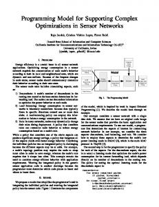
3. Requirements to Design to Code 3.1. R2D2C Method The R2D2C approach involves a number of phases, which are reflected in the system architecture shown in Figure 1. The following describes each of these phases. D1 Scenarios Capture: Engineers, end users, and others write scenarios describing intended system operation. The input scenarios may be represented in a constrained natural language using a syntax-directed editor, or may be represented in other textual or graphical forms. D2 Traces Generator: Traces and sequences of atomic events are derived from the scenarios defined in D1. D3 Model Inference: A formal model, or formal specification expressed in CSP is inferred by an automatic theorem prover—in this case, ACL2 [14]—using the traces derived in D2. A deep1 embedding of the laws of concurrency [9] in the theorem prover gives it sufficient knowledge of concurrency and of CSP to perform the inference. The embedding will be the topic of a future paper. D4 Analysis: Based on the formal model, various analyses can be performed using currently available commercial or public domain tools and specialized tools that are planned for development. Because of the nature of CSP, the model may be analyzed at different levels of abstraction using a variety of possible implementation environments. This will be the subject of a future paper. 1
“Deep” in the sense that the embedding is semantic rather than merely syntactic.
D5 Code Generator: The techniques of automatic code generation from a suitable model are reasonably well understood. The present modeling approach is suitable for the application of existing code generation techniques, whether using a tool specifically developed for the purpose, or existing tools such as FDR [3], or converting to other notations suitable for code generation (e.g., converting CSP to B [4]) and then using the code generating capabilities of the B Toolkit. It should be re-emphasized that the “code” that is generated may be code in a high-level programming language, low-level instructions for (electro-) mechanical devices, natural-language business procedures and instructions, or the like. Paraphrasing, whereby more understandable descriptions (above and beyond existing documentation) of existing systems or system components are extracted, is likely to have useful application in future system maintenance for complex systems where the original design documents have been lost or modified so much that the original design and requirements documents do not reflect the current system.
3.2. R2D2C Implementation The current R2D2C implementation translates the CSP model into Java code [5]; the derived design is transformed into an equivalent software representation. The Java programming language was selected both for tool implementation and for the target platform for the following reasons. • Java is a general-purpose concurrent class-based object-oriented programming language, with very few implementation and hardware dependencies. • An off-the-shelf implementation (library) of CSP for Java [2] is available. While it does not provide direct CSP-to-Java mapping, it conforms to the CSP model of communicating systems for Java multi-threaded applications [15]. There is also support for distributed JCSP components using JCSP.net [19]. • Java Swing [18], in combination with some Java IDEs, greatly simplifies user interface development. • Availability of many Java based translator development tools. The translators are implemented using the ANTLR [1] tool that provides a framework for constructing recognizers, compilers, and translators from grammatical descriptions. A discussion of ANTLR and some related tools can be found in [17]. A planned front end tool, a scenario editor, will support this process. An additional planned tool will enable an automated translation of constraints and restrictions into
a propositional form that can be subjected to formal proof based on the CSP model. Appropriate algorithms will be developed to analyze properties of distributed systems that use a CSP-like communication infrastructure [13]. CSP models for a specific programming language implementation further increase modeling capabilities (e.g., for Java [20]).
4. Example from NASA Hubble Robotic Servicing Mission To illustrate the application of R2D2C in the verification of complex robotic operations procedures, we select a servicing procedure from the Hubble Robotic Servicing Mission (HRSM)—which is in the planning phase of development at NASA Goddard Space Flight Center (GSFC).
4.1. Background As one of history’s most productive and significant scientific instruments, the Hubble Space Telescope (HST) has brought about new knowledge in astronomy and astrophysics as well as increased public interest in those fields. US Congressional recognition of its value resulted in the allocation of funding to begin preparation toward saving the telescope from destruction when it falls back to Earth due to orbital decay over the next decade. One possible approach to saving HST involves a Space Shuttle flight to enable astronauts to refurbish the instrument. Since the HST does not have its own propulsion system, it would have to have one installed to enable it to boost itself back to a safe orbit. This strap-on propulsion system, delivered by the Shuttle and attached to HST by the astronauts, would also enable the HST to safely de-orbit at the eventual end of its life. Another possible approach to saving the HST would involve a robotic mission that would perform the same tasks—refurbishment and attachment of a propulsion system. NASA Goddard Space Flight Center has been studying this alternative approach under the name “Hubble Robotic Servicing Mission” (HRSM). The final decision on which approach (or indeed whether any approach) will be carried out has yet to be made, at the time of writing. Originally designed to be serviced by astronauts, the HST presents challenges to developing a servicing mission based on robotics. For example, safe robotic access to replaceable internal components and safe manipulation of those components and their connections require development of unique tools, fixtures, techniques, and procedures. The satisfaction of power, communications, and physical/thermal/electrical constraints and restrictions entails a significant level of complexity in any procedures that might be used by either robotic or human servicing agents. In the following sections, we focus on the pro-
Future Bespoke Tools
Laws of Concurrency
Requirements Documentation
D1 Scenarios Capture
Scenarios
D2 Traces Generator
Traces
D3 Model Inference
CSP Spec
D4 Analyze
(Modified) CSP Spec
D5 Code Generator
existing prototype future enhancement commercially available
Theorem Prover
Visualization Tools
Existing CSP Tools
Figure 1. The R2D2C method. cedures that are being formulated for robotic agents to carry out for this servicing mission. However, it is to be understood that even if human astronauts, instead of robots, conduct the same servicing activities, the necessary procedures would be similar, and in any case would have to be formulated generally with the same level of detail and subjected to the same overall mission constraints (thermal restrictions, communications windows, etc.). The robotic servicing mission under study assumes the use of the Dextrous Robot (DR) “Dextre” built originally as the Special Purpose Dextrous Manipulator by MD Robotics, Brampton, Ontario, Canada, for exterior maintenance of the International Space Station. The procedures currently under development are proving to be extremely complex. Several of the procedures (such as the example in Section 4.3) will take several days to complete. The robots can only run for 8 hours per day, for a variety of reasons: battery life, availability of real-time communications with the ground operations center, etc. The lead time from procedure planning to ultimate implementation (if the servicing mission gets the go-ahead) is over 2 years. Even then, it is anticipated that the mission will be under pressure to prepare all of the necessary hardware and get all of the procedures in place. An additional level of complexity arises from the need to completely regenerate the time-line for all of the procedures once the robotic equipment is in orbit in proximity to the telescope. To enable real-time video of the servicing mission, two Tracking and Date Relay Satellites (TDRS) will be used to relay high-rate video data to the mission control center on the ground. However, one of the TDRS satellites will be unavailable for 12 minutes every 90 minutes, thus preventing a few of the operations for that time period. Some parts of the procedures may continue (e.g., returning the grapple arm to the ejection module), while others must be halted until the operations are once again visible to mission controllers on the ground. Although the blackout periods can be calculated, their occurrence is based on the fi-
nal orbit of the robotic devices. Therefore, the exact blackout times can only be calculated after launch, at which point some of the procedures, especially those with tasks that exceed 78 minutes, may need to be regenerated.
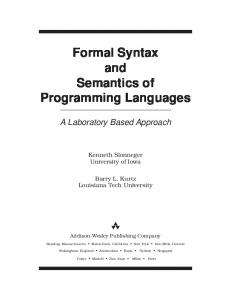
4.2. Procedures Figure 2, consisting of two screen shots from a run of the prototype R2D2C tool, illustrates the use of R2D2C for a simple procedure fragment. Figure 2(a) shows the natural language input stage, while Figure 2(b) illustrates the generated CSP equivalent.
4.3. Specification of a possible procedure to replace the Wide Field Camera (WFC) We will consider a portion of one possible version of a procedure for robotic replacement of the Wide Field Camera (WFC), chosen from an early version of the vast collection of servicing procedures that have been developed to date. We use this example to show, for one hypothetically possible case, how an error in the procedure could be found automatically by the R2D2C tool. We will illustrate its mapping from a natural language description to a formal model upon which to perform reasoning and analysis to detect errors (e.g., deadlocked actions or violations of constraints or restrictions). An additional possible result (not illustrated here) would be to transform the formal model into an implementation consisting of appropriate code that would, for example, represent actual instructions that could be executed by the robot. The robotic elements involved in the procedure are the Grapple Arm (GA), Dextrous Robot #1 (DR1), and Dextrous Robot #2 (DR2), along with a collection of special tools, tool caddies, fixtures, etc. The other relevant items for the procedure include the ejection module (EM), the new WFC, and the HST itself with the old WFC that is to be replaced.
Figure 2. Snapshots of the R2D2C tools. (a) Natural language input; (b) generated CSP specification.
A sample procedure description is provided in Table 1. This is the actual procedure description that will be used in the HRSM (currently, the descriptions are written in this format in MS Word with XML). The procedure describes how to remove the WFC Tool Caddy from stowage. Initially, GA, DR1, and DR2 are powered up, checked, and readied to perform the retrieval of the WFC Tool Caddy. Only one of GA, DR1, and DR2 should move at any time in order to avoid possible collision and damage to the robot. This “mutual exclusion” rule must be maintained in the procedure specifications. The GA then positions the robot in front of the EM. One of the dextrous
robots is then stabilized, while the other dextrous robot removes the WFC Tool Caddy. The fragment starts when GA sets the brakes. DR1 then releases the brakes, stabilizes, and sets the brakes. DR2 then releases the brakes, acquires the WFC Tool Caddy and sets the brakes. The fragment of the procedure that we address here can be stated in restricted natural language (Figure 3). R2D2C then translates the fragment into CSP (Figure 4). The CSP notation used is limited to the ACII character set to insure compatibility with the other tools used. This specification is very simple and does not capture the sequential operation of GA, DR1, and DR2 and the “mu-
001:00:00 001:00:15
GA Daily GA/DR Power Up and Checkout (00:15) Retrieve WFC Tool Caddy (01:33) Command EM tool stowage door open:
DR1 Daily GA/DR Power Up and Checkout (00:15) Retrieve WFC Tool Caddy (01:33)
DR2 Daily GA/DR Power Up and Checkout (00:15) Retrieve WFC Tool Caddy (01:33)
• Release Brakes (00:01) • Maneuver to EM tool stowage location (00:10) • Set Brakes (00:01)
• Release Brakes (00:01) • Stabilize (00:15) • Set Brakes (00:01)
• Release Brakes (00:01)
• Acquire WFC Tool Caddy Micro-Fixture (00:20) • Release WFC Tool Caddy stowage bolt (00:10) • Remove WFC Tool Caddy from stowage (00:20) • Set Brakes (00:01)
• Release Brakes (00:01) • Release from Stabilization (00:10) • Set Brakes (00:01) Table 1. Sample WFC procedure
GA sends brakeset. DRone receives brakeset then sends brakerelease then sends stabilize then sends brakeset. DRtwo receives brakeset then sends wfctoolaquire then sends brakeset. Figure 3. A simplified procedure fragment tual exclusion” requirement. Additionally, some steps for the DR2 operation are omitted. The next step is to add sequential constraints (Figure 5). DR2 cannot continue until it receives a sequence of messages (brakerelease, brakeset) which is possible only when
DR1 completes its task. The corresponding CSP is shown in Figure 6. Constraints incorporated into the prototype R2D2C tool are, at this stage, minimal in number, but serve to demonstrate the potential of the R2D2C method in verifying
channel brakerelease, brakeset, stabilize, wfctoolaquire : T ; GA = brakeset ! 0 -> GA ;\\ DRone = brakeset ? x -> brakerelease ! 0 -> stabilize ! 0 -> brakeset ! 0 -> DRone ; DRtwo = brakeset ? x -> wfctoolaquire ! 0 -> brakeset ! 0 -> DRtwo ; System = DRone [| {| |} |] DRtwo [| {| |} |] GA ; process GA = brakeset!0 → GA process DRone = brakeset?x → brakerelease!0 → stabilize!0 → brakeset!0 → DRone process DRtwo = brakeset?x → wfctoolaquire!0 → brakeset!0 → DRtwo process System = DRone k DRtwo k GA Figure 4. An example fragment of the Wide Field Camera replacement procedure, as translated into CSP, (a) in plain text, (b) prettyprinted.
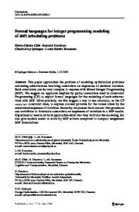
GA sends brakeset. DRone receives brakeset then sends brakerelease then sends stabilize then sends brakeset. DRtwo receives brakerelease then receives brakeset then sends wfctoolaquire then sends brakeset. Figure 5. A simplified sequential procedure fragment robotic servicing procedures for the Hubble. To provide an illustration of the capability for automatic error discover, we imagine that a real-time repair mission operations contingency has occurred and that the above procedure fragment is proposed to be changed. DR2, due (in this imagined contingency) to some technical problems, cannot release the WFC Tool Caddy stowage bolt. As a consequence, DR1 now has to release the bolt to enable DR2 to acquire the WFC Tool Caddy (Figure 7). The prototype R2D2C tool transforms this scenario into the CSP model in Figure 8. The tool automatically performs a range of analysis and verification steps on this formal model, resulting in the detection of a violation of a servicing-mission constraint 9. The violation is a deadlock that will cause DR2 to block. Adding the bolt release at the end of the sequence, rather than before setting the brakes, will give the result that the trace (or sequence of messages) (boltrelease, brakeset) will not be generated. Instead the sequence will be (brakeset, boltrelease).
Although very simple, this error has a degree of subtlety and might easily occur in the planning of the procedures. DR2 releases the brakes at the same time DR1 sets the brakes, thus violating the sequentiality requirement—an error automatically detected by the R2D2C tool. The full body of constraints and restrictions number in the many hundreds, and have been formulated and documented for the HRSM. Compiled into the Constraints and Restrictions Document (CARD), they embody a great deal of complexity and become very demanding to apply manually to validate a procedure, which provides considerable justification for developing an automated means for procedure verification. The R2D2C tool can incorporate, and automates the application of, arbitrarily many HRSM constraints and restrictions as well as other kinds of verification analysis to detect errors and problems such as omissions, deadlock, livelock, and unreachable steps.
channel brakerelease, brakeset, stabilize, wfctoolaquire : T ; GA = brakeset ! 0 -> GA ; DRone = brakeset ? x -> brakerelease ! 0 -> stabilize ! 0 -> brakeset ! 0 -> DRone ; DRtwo = brakerelease ? x -> brakeset ? x -> wfctoolaquire ! 0 -> brakeset ! 0 -> DRtwo ; System = DRone [| {| |} |] DRtwo [| {| |} |] GA ; process GA = brakeset!0 → GA process DRone = brakeset?x → brakerelease!0 → stabilize!0 → brakeset!0 → DRone process DRtwo = brakerelease?x → brakeset?x → wfctoolaquire!0 → brakeset!0 → DRtwo process System = DRone k DRtwo k GA Figure 6. CSP for the sequential procedure fragment, (a) in plain text, (b) prettyprinted.
GA sends brakeset. DRone receives brakeset then sends stabilize then sends brakeset then sends boltrelease . DRtwo receives boltrelease then receives brakeset then sends wfctoolaquire then sends brakeset. Figure 7. Modified sequential procedure fragment
4.4. Results and Future Tool Support The application of the prototype R2D2C tool to the example described above shows the potential benefit of an automated, mathematically sound method for verifying the Hubble robotic servicing procedures. Demonstrating that it can automatically detect violations of the documented HRSM constraints and restrictions was an important step towards establishing that the benefits existed for HRSM. To move forward, it will be necessary to augment the prototype R2D2C tool to ease the process of expressing HRSM procedures in a form that can be automatically translated into a formal CSP model.
5. Related Work Harel [6] [8] has advocated scenario-based programming through UML use cases and play-in scenarios. The present work differs in that it uses scenarios in the form of structured text that is easily understandable by engineers and
non-engineers. In addition, the results of converting the structured text to traces and then from traces to a formal model allows us to use a wide range of formal methods tools (e.g., model checkers), which can be used to verify and validate the system [10]. NASA Ames has been working on the automatic translation of UML use cases to executable code, and report success in using the approach on large applications [21]. Our approach is different, however, in that we are not limited to UML use cases, nor to natural language. R2D2C accommodates any input mechanism whereby requirements can be represented as scenarios, and traces extracted. Our approach works equally well with graphical, mathematical, and textual requirements representations. More importantly, the key to our approach and what makes it invaluable for high-dependability applications is the full formal basis, and complete mathematical tractability from requirements through to code. To our knowledge, no other currently available automated development methodology can make this claim [10].
channel boltrelease, brakeset, stabilize, wfctoolaquire : T ; GA = brakeset ! 0 -> GA ; DRone = brakeset ? x -> stabilize ! 0 -> brakeset ! 0 -> boltrelease ! 0 -> DRone ; DRtwo = boltrelease ? x -> brakeset ? x -> wfctoolaquire ! 0 -> brakeset ! 0 -> DRtwo ; System = DRone [| {| |} |] DRtwo [| {| |} |] GA ; process GA = brakeset!0 → GA process DRone = brakeset?x → stabilize!0 → brakeset!0 → boltrelease!0 → DRone process DRtwo = boltrelease?x → brakeset?x → wfctoolaquire!0 → brakeset!0 → DRtwo process System = DRone k DRtwo k GA Figure 8. CSP for the modfied sequential procedure fragment. sets of the development lifecycle, there has been heretofore a “jump” in deriving from the requirements the formal model that is a prerequisite for sound automatic code generation. Yet, R2D2C is a simple approach, combining techniques and notations that are well understood, well tried and tested, and trusted. The novelty of the approach, and the part of the approach that achieves continuity in the development process, is the use of a theorem prover to reverse the laws of concurrency, and to achieve levels of inference that would be impossible for a human being to perform on all but trivial systems. It is our contention that R2D2C, and other approaches that similarly provide mathematical soundness throughout the development lifecycle will: • Dramatically increase assurance of system success by ensuring – completeness and consistency of requirements Figure 9. Snapshot of the R2D2C tool detecting a deadlock error in example HRSM procedure.
6. Conclusions and Future Work R2D2C is a unique approach to the automatic derivation of complex systems. It is unique in that it supports fully (mathematically) tractable development from requirements elicitation through to automatic code generation (and back again). While other approaches have supported various sub-
– that implementations are true to the requirements – that automatically coded systems are bug-free – that implementation behavior is as expected • Decrease costs and schedule impacts of complex systems through automated development • Decrease re-engineering costs and delays Future work will include improving the quality and extent of the embedding of CSP in ACL2, and optimizing that for efficiency. We plan a plethora of support tools to allow us to easily change the level of abstraction in a formal model, to visualize various system models and changes
in those models, and to aid in tracking changes through the development process (or the reverse engineering process). We plan to enhance our existing prototype to support the full version of R2D2C, to make it into a fully functional robust prototype, and to apply it to more significant examples than the one presented in this paper.
Acknowledgements This work was encouraged and funded in part by NASA Goddard Space Flight Center (GSFC) Information Systems Division and the GSFC Technology Transfer Office. We are grateful to Joe Hennessy, Ted Mecum, Nona Cheeks, Chris Kirkman, Diana Cox, Yvette Conwell-Brown, and Keith Dixon for their support and encouragement. John Erickson (University of Texas at Austin) worked with us and provided invaluable expertise on the prototype R2D2C environment. We are grateful to the HRSM team, particularly Rud Moe and Richard Strafella, for their support and collaboration. The approach described in this paper is protected under United States and international Patent Applications assigned to the United States government.
References [1] ANTLR: ANother Tool for Language Recognition. http://www.antlr.org/. [2] Communicating sequential processes for Java (JCSP). http://www.cs.kent.ac.uk/projects/ofa/jcsp/. [3] Failures-Divergences Refinement: User Manual and Tutorial. Formal Systems (Europe), Ltd., 1999. [4] M. J. Butler. csp2B : A Practical Approach To Combining CSP and B. Declarative Systems and Software Engineering Group, Department of Electronics and Computer Science, University of Southampton, February 1999. [5] J. Gosling, B. Joy, G. Steele, and G. Bracha. JavaTM Language Specification. Addison Wesley, Boston, second edition, 2000. [6] D. Harel. From play-in scenarios to code: An achievable dream. IEEE Computer, 34(1):53–60, 2001. [7] D. Harel. Comments made during presentation at “Formal Approaches to Complex Software Systems” panel session. ISoLA-04 First International Conference on Leveraging Applications of Formal Methods, Paphos, Cyprus. 31 October 2004. [8] D. Harel and R. Marelly. Come, Let’s Play: Scenario-Based Programming Using LSCs and the Play-Engine. SpringerVerlag, 2003. [9] M. G. Hinchey and S. A. Jarvis. Concurrent Systems: Formal Development in CSP. International Series in Software Engineering. McGraw-Hill International, London, UK, 1995. [10] M. G. Hinchey, J. L. Rash, and C. A. Rouff. A formal approach to requirements-based programming. In Proc. IEEE International Conference and Workshop on the Engineering of Computer Based Systems, ECBS-2005, Greenbelt, Maryland, USA, 4–5 April 2005. IEEE Computer Society.
[11] C. A. R. Hoare. Communicating sequential processes. Communications of the ACM, 21(8):666–677, 1978. [12] C. A. R. Hoare. Communicating Sequential Processes. Prentice Hall International Series in Computer Science. Prentice Hall International, Englewood Cliffs, NJ, 1985. [13] S. T. Huang. A distributed deadlock detection algorithm for CSP-like communication. ACM Transactions on Programming Languages and Systems, 12(1):102–122, 1990. [14] M. Kaufmann and Panagiotis Manolios and J Strother Moore. Computer-Aided Reasoning: An Approach. Advances in Formal Methods Series. Kluwer Academic Publishers, Boston, 2000. [15] D. Lea. Concurrent Programming in JavaTM : Design Principles and Patterns. The JavaTM Series. Addison-Wesley Professional, Reading, Massachusetts, second edition, 2000. [16] D. L. Parnas. Using mathematical models in the inspection of critical software. In Applications of Formal Methods, International Series in Computer Science, pages 17–31. Prentice Hall, Englewood Cliffs, NJ, 1995. [17] Y. Smaragdakis, S. S. Huang, and D. Zook. Program generators and the tools to make them. In PEPM ’04: Proceedings of the 2004 ACM SIGPLAN Symposium on Partial Evaluation and Semantics-Based Program Manipulation, pages 92– 100. ACM Press, 2004. [18] K. Walrath, M. Campione, A. Huml, and S. Zakhour. JFC Swing Tutorial, The: A Guide to Constructing GUIs. Addison Wesley, Boston, second edition, 2004. [19] P. H. Welch, J. R. Aldous, and J. Foster. CSP networking for Java (JCSP.net). In Proceedings of the Global and Collaborative Computing Workshop (ICCS 2002), volume 2330 of Lecture Notes in Computer Science, pages 695–708. Springer-Verlag, 2002. [20] P. H. Welch and J. M. R. Martin. A CSP model for Java multithreading. In Proc. International Symposium on Software Engineering for Parallel and Distributed Systems, pages 114–122, June 2000. [21] J. Whittle, J. Saboo, and R. Kwan. From scenarios to code: An air traffic control case study. In Proc. ICSE-25, 25th IEEE/ACM International Conference on Software Engineering, pages 490–495, Portland, Oregon, 2003. IEEE Computer Society Press.