speci cation of 188-220, and gives examples of errors ..... 1~16 dest addr*, Type 2 connection status) ... for the Network layer has 7,150 lines of code, de ning .... good set of test scripts should at least check those ..... e7 e5 e6 e7 e6 e7 e7 e11e9 e12 e0 e9 e9 e1 e6. Fig. 8. Minimum-cost test sequence ..... Similarly, the accu-.
FORMAL SPECIFICATION AND CONFORMANCE TESTING OF ARMY COMMUNICATIONS PROTOCOLS Paul D. Amer Mariusz A. Fecko Adarshpal S. Sethi
Computer and Information Sciences Department University of Delaware, Newark, DE
M. U mit Uyar Ali Y. Duale
Electrical Engineering Department The City College of the City University of New York, NY
ABSTRACT
I. Introduction
During the past six years, ATIRP-sponsored faculty and students from the University of Delaware and the City College of New York, collaborating with scientists from CECOM and ARL, have helped advance the state-of-the-art in the design, development, and testing of Army communications protocols1 . Working closely together, these groups speci ed a complex real-life protocol (MIL-STD 188-220) in Estelle, and then used that formal speci cation to generate conformance test sequences. The test generation e�ort involved identifying and publishing results on three theoretical problems: (1) the timing constraint problem, (2) the controllability problem, and (3) the con icting timers problem. Based on ATIRP's research results, two software packages were written to generate conformance test sequences for 188-220. These packages helped generate tests for 188-220's Data Link Types 1 and 4 services that were realizable without timer interruptions while providing a 200% increase in test coverage. The test cases have been delivered and are being used by a CECOM conformance testing facility.
This paper summarizes a successful six-year e�ort to use the Estelle formal description technique to specify a complex real-life protocol - Military Standard (MIL-STD) 188-220 - and then use that speci cation to automatically generate conformance tests for use in implementation testing. A key factor in this success story has been the ATIRP-sponsored collaboration among ve groups: University of Delaware (UD), City College of the City University of New York (CCNY), the Army Research Laboratory (ARL), US Army Communications-Electronics Command (CECOM), and the Joint Combat Net Radio Working Group (CNR-WG). 188-220 is being developed in the US Army, Navy and Marine Corps systems for mobile combat network radios [18]. As a result of this collaboration, the synergistic framework to develop C 4 I (Command, Control, Communications, Computers, and Intelligence) systems with the help of formal methods serves as a model for future DoD networking standards development [20]. Since this paper is a case study promoting a successful application of Estelle to a real-life protocol, it includes a cross section of activities over the past six years. Section II provides the background on the collaboration among the MIL-STD 188-220 sponsors, research and development teams, and standards organizations. Sections III and IV overview the formal description technique Estelle and 188-220, respectively. Section V presents a part of the Estelle speci cation of 188-220, and gives examples of errors and ambiguities found as a result of formally specify-
Keywords: conformance testing, Estelle, formal de-
scription technique, formal speci cation, MIL-STD 188-220, protocol speci cation, test case generation This work supported by the US ARO (DAAH04-94-G0093), and prepared through collaborative participation in the Advanced Telecommunications/Info Dist'n Research Program (ATIRP) Consortium sponsored by the US Army Research Lab under Fed Lab Program, Cooperative Agreement DAAL01-962-0002. M. Fecko is with Telcordia Applied Research, NJ. A. Duale is with IBM, NY. 1
1
ing the protocol. A general approach adopted at UD and CCNY to test generation from an Estelle formal speci cation is described in Section VI. This section also summarizes four years of ATIRP-supported published research results in test generation based on formal speci cations. Section VII presents two systems of software: (1) efsm2fsm -rcpt, and (2) INDEEL implemented to help generate conformance tests. Section VIII summarizes our practical test generation results - the technology transfer of tests from ATIRP to CECOM. Finally, Section IX presents the authors' personal perspective on how the protocol development process is in general improved thanks to using formal methods.
sents one of the rst major national or international standards o�cially including an Estelle speci cation. Other examples include [31], [34], [35], [52]. During this period, CECOM has been concurrently developing a Conformance Tester that can automatically evaluate a 188-220 implementation identifying its conformance with the standard. Our test generation research was initiated as part of the US Army's Advanced Telecommunication and Information Distribution Research Program (ATIRP) in January 1996, when UD's Protocol Engineering Lab began research collaboration with CCNY. E�orts were focused on automatically generating test cases from the Estelle speci cations. Generating tests from formal speci cations such as pure nite state machines (FSMs) has been extensively studied in the literature. But the inherent complexity of 188-220 is far beyond specifying with pure FSMs, hence the need to use a more powerful speci cation language such as Estelle, International Standard ISO 9074. Unfortunately, generating tests from Estelle speci cations presents di�cult theoretical and practical problems. UD and CCNY faculty and students continue to investigate these problems with the practical motivation of applying the results towards 188-220 test case generation.
II. History of MIL-STD 188-220 Development Formal methods in communications protocol speci cation and conformance testing have been widely used in the design and testing of real-life protocols [6], [16], [17], [28], [39], [40], [84]. In particular, the Estelle formal description technique (FDT) [11], [32], [61], [64] has been used on several occasions to resolve ambiguities within international protocols [8], [14], [38], [53], [62], [77]. In 1994, UD's Protocol Engineering Laboratory began its involvement with the US Army in using Estelle to formally specify the military standard MILSTD 188-220 [18]. An initial small contract with the Army Research Laboratory supported both simulation and speci cation of the 1993 version of 188220 [13], [49]. This formal speci cation research effort received the attention of the CECOM Software Engineering Center in NJ. CECOM leads the e�ort to evolve 188-220 to meet the Army's requirements for battle eld digitization, through the Joint CNRWG, itself responsible for the evolving 188-220 standard.
Automatic generation of tests from Estelle speci cations presented various theoretical problems: 1. During testing, if active timers were not taken into account when the tests were generated, these timers can disrupt the test sequences, thereby failing correct implementations or worse, passing incorrect ones. For accurate testing, timers must be incorporated as constraints into the extended FSM (EFSM) model of an Estelle speci cation. 2. Test sequence generation is limited by the controllability of an Implementation Under Test (IUT) [7]. Testers may not have direct access to all interface(s) in which the IUT accepts inputs. Typically, the interfaces with upper layers, or with timers are di�cult or impossible to access during real testing conditions. In this case, some inputs cannot be directly applied; the interactions involving such interfaces may render some portions of the protocol untestable, and may introduce non-determinism and/or race conditions during testing. 3. Infeasible test sequences may be generated unless
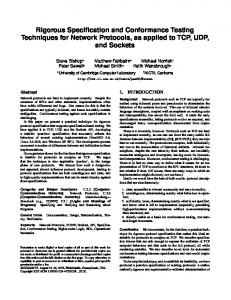
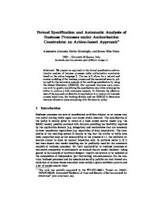
From 1995 to 1998, over fty changes to the English speci cation of 188-220 resulted from UD's e�orts using Estelle to formally specify the standard [2], [18] (see Figure 1). While the English text takes precedence in case of disagreement with the formal speci cation, UD's Estelle speci cation of 188-220 is an o�cial part of the military standard. 2 It repre2 From this point on, 188-220 refers to version B, approved 1/98.
2
May 93
Oct 95
July 95 - “A” July 97 - draft “B” Jan 98 - approved “B”
June 96 March 97 Jan 98
MIL-STD 188-220 (Estelle)
(English)
Combat Net Radio Working Group CECOM
Protocol Engineering Lab University of Delaware
Fig. 1. History of MIL-STD 188-220 Development
con icting conditions based on a protocol's variables are resolved (the INDEEL software package (Section VII-B addresses this problem). 4. In particular, infeasible test sequences may result from a protocol's variables modeling multiple timers that may be running simultaneously (the so-called con icting timers problem).
municating extended nite state machines. To avoid ambiguity among di�erent readers of a speci cation, the Estelle language itself has a formal, mathematical, implementation-independent semantics. Estelle is an expressive, well-de ned, well-structured language that is capable of specifying distributed, concurrent information processing systems in a complete, consistent, concise, and unambiguous manner. An Estelle speci cation aims at discovering and resolving ambiguities in the original English document that would cause interpretation problems for implementors.
The timing and controllability issues were present in the EFSM model of the Estelle speci cation of MIL-STD 188-220 [3], [21]. Based on the results of investigating problems (1) and (2) by the UD and CCNY joint group [21], [23], [72], UD has been providing CECOM with automatically generated test sets since 1997. The sizes of the resulting FSMs derived from the Estelle speci cation range from 48 to 303 states, and from 119 to 925 transitions. The corresponding test sequences range from 145 to 2,803 test steps. These tests are free of interruptions due to unexpected timeouts while their coverage of the number of testable transitions increased from approximately 200 to over 700 by utilizing multiple interfaces without controllability con icts. The most recent research focuses on the con icting timers problem.
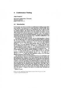
An Estelle speci cation consists of two parts: an architecture and its behavior. The architecture speci es a collection of systems of nested modules. Each module's behavior is described by an extended FSM. These EFSMs interact via the sending of interactions over a set of channels. The interactions are conceptually stored in in nite FIFO queues enabling transitions in the receiving module which are red when all enabling conditions are satis ed. A complex set of rules de ne either a parallel or synchronous ring of transitions within each EFSM. Overall, the many features of Estelle allow a user to formally specify a III. Estelle wide variety of network protocol behaviors. Further information about Estelle can be found in [61], [64]. In 1989, Estelle was published as one of two ISO International Standard Formal Description Techniques One major bene t of an Estelle speci cation as a (FDT) for the speci cation of computer communica- model of a communication protocol is that it can be tion protocols [11], [32]. As shown in Figure 2, Es- used as input to a conformance test generation tool. telle speci es a protocol's behavior as a set of com3
• Behavior: -
Communicating Extended FSMs + Pascal
variables priorities delays conditionals
• Architecture: Hierarchy and Interconnections of EFSMs - modules - interaction points - channels
Fig. 2. Estelle: ISO International Standard 9074
Since Estelle makes it possible to create a complete and unambiguous protocol model, the test cases generated from it can potentially achieve higher fault coverage than hand-generated ones, and are reproducible with far less e�ort as 188-220 evolves in the future. These advantages are the primary motivations for using Estelle to specify 188-220.
support for new radio technology and integration with Internet protocols (commercial IP, TCP, and UDP at the network and transport layers). Version 188-220B, whose architecture is depicted in Figure 3, describes the protocols needed to exchange messages using CNR as the transmission media. These protocols include the physical, data link and part of the network layer of the OSI model. The protocols apply to the interface between host systems and radio systems. Hosts usually include communications processors or modems that implement these lower layer protocols. The unshaded portions of Figure 3 indicate those protocols and extensions that were developed speci cally for use with CNR.
IV. MIL-STD 188-220 The Protocol Engineering Lab researchers at UD used Estelle to specify parts of the 188-220 protocol suite. This suite was developed to meet the requirements for horizontal integration, seamless Internet communications and increased mobility using combat network radios [20]. This protocol, a critical piece of the new Joint Technical Architecture, is now mandated for CNR communications. It is being implemented in US Army, Navy and Marine Corps systems, and has been demonstrated initially during the Army's Advanced War ghting Experiment in 1997. 188-220 is now receiving allied/international attention, while portions of its protocol architecture have been promulgated in the Internet Engineering Task Force. Expected outcomes from its use are: seamless connectivity of C4 I systems (discussed brie y in Section IX), horizontally integrated information networks, and joint interoperable C4 I systems for the war ghter.
MIL-STD-188-220 Datalink layer speci es several service types, each intended to handle di�erent types of tra�c with di�erent quality of service (QoS) demands. A 188-220 station can actually process several di�erent types of tra�c simultaneously (and almost orthogonally). MIL-STD-188-220 Network Layer consists of Internet (IP) Layer, Subnetwork Dependent Convergence Function (SNDCF), and Intranet Layer. The Intranet Layer has been dedicated to routing intranet packets between a source and possibly multiple destinations within the same radio network. The Intranet Layer also accommodates the rapid exchange of topology and connectivity information|each node on the radio network to determine which nodes are on the network 188-220, originally developed in 1993, evolved to 188- needs and how many hops away they are currently located. 220A with substantial new functionality, including 4
Fig. 3. MIL-STD 188-220 Protocol Architecture. The circles indicate those parts of the protocol where FDTs were used during the development.
Network Layer - IP, SNDCF, Intranet Interface
Network Layer Interface
Transport Layer
1 2,3 O p 7,8,9,10,11,12 e r Network Layer a t o 13,14,15 r 4
5,6
Datalink Layer
1. NL-Unitdata.Req 2. NL-Unitdata.Ind 3. NL-Status.Ind 4. DL-Unitdata.Req (DL-Unitdata-id*, 1~16 dest addr, src addr, top-id, precedence, throughput, delay, reliability, data, data length) 5. DL-Unitdata.Ind (1~16 dest addr, src addr, top-id, data, data length) 6. DL-Status.Ind (DL-Unitdata-id*, ack failure, 1~16 dest addr*, Type 2 connection status) 7. OP-join-net.Req 8. OP-leave-net.Req 9. OP-TU-response-mode (response mode) 10. OP-TU-relay-mode (relay mode) 11. OP-TU-topology-precedence (precedence) 12. OP-TU-min-update-per (period) 13. OP-unable-to-join-net.Ind 14. OP-join-net.Ind 15. OP-leave-net.Ind
1 2,3
Internet (IP) Layer o 21 p 22,23 e OSAP Subnetwork Dependent r 7,8 Convergence Function a 13,14,15 t 24 o 25,26 r Intranet Layer 9,10,11,12
7. OP-join-net.Req 8. OP-leave-net.Req 9. OP-TU-response-mode (response mode) 10. OP-TU-relay-mode (relay mode) 11. OP-TU-topology-precedence (precedence) 12. OP-TU-min-update-per (period) 13. OP-unable-to-join-net.Ind 14. OP-join-net.Ind 15. OP-leave-net.Ind 21. SNDCF-Unitdata.Req 22. SNDCF-Unitdata.Ind 23. SNDCF-Status.Ind 24. IL-Unitdata.Req (IL-Unitdata-id*, message type,1~16 dest addr, src addr, precedence, throughput, delay, reliability, data, data length) 25. IL-Unitdata.Ind (IL-Unitdata-id*,1~16 dest addr, src addr, data, data length) 26. IL-Status.Ind (IL-Unitdata-id*, ack failure, intranet path status, 1~16 dest addr)
4 5,6
Fig. 4. Network Layer Interface and Architecture
V. 188-220 Estelle Speci cation
lines of code, respectively. The Estelle source code for the Network layer has 7,150 lines of code, de ning To help a reader realize the magnitude of formally 34 states and 370 transitions in 7 EFSMs. specifying a protocol of 188-220 size and complexity, we provide some numbers. The Datalink and Net- Due to its large size, it is not possible to include work layer speci cations consist of 69 and 19 doc- the actual Estelle speci cations in this paper. For uments, respectively, describing the architecture, in- a more detailed description of the semantics of Esterfaces, EFSM, and state table of each module. The telle speci cation components (communication chanDatalink layer speci cation is accompanied by three nels, interactions, etc.), the reader may should see Estelle source code les (for Datalink classes A, B, www.cis.udel.edu/�amer/CECOM/. In the next secand C) with approximately 1,600, 8,700, and 2,400 tion, we present an overview of the Network Layer 5
SNDCF Layer SNDCFSAP o p e r a t o r
13,14,15
7,8 60,61,62,63
64,65,66,67
TOP-UPDATEREQ Timer
TOP-UPDATE Timer
24
END-ENDACK Timer
XNP procedures 70, 71 72
40, 40, 41, 41 72
50
46
42 43,44,45
47,48,49
73
9,10,11,12
73, 74
25,26
51,52
Source Directed Relay
Topology Update 53,54 4
4
lower mux 5,6
LSAP
lower mux 5,6
Datalink Layer
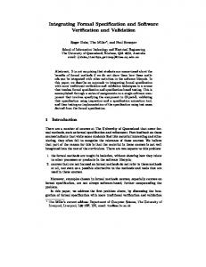
Fig. 5. Intranet Layer Architecture
architecture with a focus on the Topology Update timers, one for each IP packet that has been sent and Source Directed Relay functions of the Intranet but not yet acknowledged. The TU module interacts sublayer. with the SDR module by notifying it of any topology changes that take place dynamically. The TU module communicates with two timers: Topology Update A. Intranet Layer Architecture Timer and Topology Update Request Timer. The former is started after a topology update message is sent Figure 4 shows the interface and general architecture by the station. According to 188-220A, a station is of the Network layer. The architecture represents the not allowed to send another topology update mesprotocol stack at a single station, as well as an in- sage until the timer expires. The latter performs the terface with \operator module" which can interact same role for topology update request messages. with several di�erent layers in the stack. The operator module abstracts the link layer's interactions Both SDR and TU modules can send and rewith both a human operator and a system manage- ceive messages from the datalink layer through their ment process.3 lower mux interaction points|the messages from the two modules are multiplexed by the parent Intranet Figure 5 shows the internal structure of the Intranet Layer module. A peer operator or management comLayer. The two main Intranet Layer functionalities, ponent is connected directly to the Topology Update Source Directed Relay (SDR) and Topology Update module and can set parameters that are relevant in exchange (TU), were encapsulated in separate com- topology update mechanism. Part of the diagram ponent modules of the Intranet Layer module. This inside the dash-lined rectangular contains modules simpli es the design of the FSMs that model the en- that handle XNP procedures: joining and leaving tire layer, and also allows for generating test cases the net with either centralized or distributed control, for each functionality separately. and parameter update requests. The SDR module receives IL Unitdata Req messages through SNDCFSAP interaction point. It B. Problems and Ambiguities Found in 188-220 starts/stops a varying number of END END ACK through Formal Speci cation Note that the numbers in Figures 4 through 5 refer to interactions, and are consistent throughout the gures (e.g., number 12 refers to OP-min-update-per in all three gures). 3
The primary goals in developing a formal speci cation of a protocol are to: 6
1. discover and document problems and ambiguities that are commonly seen in a standard written in natural language, 2. verify the protocol, 3. simulate the protocol, 4. automate code implementation, and 5. automate test generation process.
lack of acknowledgment after the maximum allowed number of retransmissions.
VI. Test Case Generation Test scripts (test cases) specify a logical sequence of test steps that are performed by a Conformance Tester to individually test a given protocol entity. The test scripts are input to the Conformance Tester which in turn stimulates an IUT, and assesses the IUT's responses to determine if the IUT correctly implements the protocols. Since it is impossible to exhaustively test an implementation in practice, a good set of test scripts should at least check those events that a�ect state/transition, boundary conditions, and stress points. The test scripts themselves should be structured as independent modular components to facilitate modifying and adding to the scripts in response to 188-220's continuing evolution.
MIL-STD 188-220 project focuses on goals (1), (3), and (5), with simulation studies done by the US Army as reported in [20]. Although the formal veri cation of 188-220 is not part of the project, some of the errors found during the formal speci cation can also be classi ed as part of goal (2). Achieving goal (4) is an open issue; manufacturers, which were already developing implementations before the Estelle speci cation was created, now have an option to use the Estelle speci cations for automated code generation.
A number of techniques have been proposed to generate test sequences from Estelle speci cations [46], [47], [65], [66], [82]. However, full Estelle speci cations of large systems may prove to be too complex for direct test case generation. As shown in Figure 6, there are several ways of generating test sequences from Estelle speci cations. One approach would be to expand Estelle's EFSMs thereby converting them to pure FSMs. This expansion would be useful since methods exist for generating tests directly from pure Examples range from ambiguities such as: FSMs (e.g., [1]). Unfortunately, completely converting even a simple EFSM can result in the state ex� \... a station shall wait for some period of time plosion problem, that is, the converted FSM may bounded by the probability of the remote ack time have so many states and/or transitions that either expiration." it takes too long to generate tests, or the number of � The Intranet Layer allows a station to enter Quiet tests generated is too large for practical use. mode whereas the Data Link layer refers to a station being in response mode o�. It was ambiguous how As an alternative, the UD and CCNY ATIRP rethese two terms di�er, if at all. search group used an intermediate approach, where an Estelle EFSM is partially expanded (hence reto more serious examples of correctness/completeness sulting in some more states and transitions), but not such as: expanded completely to a pure FSM. The EFSM is � Intranet routing was originally de ned based on expanded partially just enough to generate a set of that is feasible and practical in size. Determinspanning trees of the Intranet topology. However tests which features to expand in the general case is the draft standard's examples did not comply with ing the di�cult aspect of this research. the mathematical de nition of a spanning tree. � The phrase \may report to the higher layer pro- Test Case Generation Research: tocol, and may initiate appropriate error recovery action" was added in several locations when the Conformance test generation techniques reported in datalink layer identi ed an error condition such as a literature [1], [7], [43], [50], [59], [66], using a deter-
In the process of developing the Estelle speci cations of the Data Link and Intranet Layers, more than fty problems in the original English speci cation have been documented. All of these problems were reported back to the CNR Working Group and subsequently corrected in the standard. Here we present just two examples of ambiguities found and corrected, demonstrating the di�culty of de ning protocol operations in a natural language.
7
Estelle (EFSM) specification
“Constrained Postman Tours” Fecko, Uyar, Amer, Sethi
EFSM to FSM Conversion? Too difficult
Pure FSM
“Approximate” FSM +
Tests
1. timing constraint problem 2. controllability problem 3. conflicting timers problem
Fig. 6. Test Generation from Extended FSMs
ministic nite-state machine (FSM) model of a protocol speci cation, focus on the optimization of the test sequence length. However, an IUT may have timing constraints imposed by active timers. If these constraints are not considered during test sequence generation, the sequence may not be realizable in a test laboratory. As a result, valid implementations may incorrectly fail the conformance tests, or nonconformant IUTs may incorrectly pass the tests.
A. Research Area 1: The Timing Constraint Problem
During testing, traversing each state transition of an IUT requires a certain amount of time. A test sequence that traverses too many self-loops (a self-loop is a state transition that starts and ends at the same state) in a given state will not be realizable in a test laboratory if the time to traverse the self-loops exceeds a timer limit as de ned by another transition originating in this state. In this case, a timeout will inadvertently trigger forcing the IUT into a di�erent state, and thereby disrupting the test sequence before all of the self-loops are traversed. If this unrealizable test sequence is not avoided during test generation, most IUTs will fail the test even when they meet the speci cation. Clearly, this is not the goal of testing. Therefore, a properly generated test sequence must take timer constraints into account.
Another problem in test sequence generation is due to the limited controllability of an IUT. Typically, the inputs de ned for the interfaces with upper layers or with timers cannot be directly applied by the tester. In this case, the testability of an IUT may severely be reduced; in addition, non-determinism and/or race conditions may occur during testing. In Sections VI-A and VI-B, we outline our earlier research results to eliminate the timing constraints and controllability problems which appear in the EFSM model of the 188-220. Our recent research focus on the so-called con icting timers problem, where infeasible test sequences may be generated unless con icting conditions based on timers are resolved. These results are described in Section VI-C.
Our research resuls [72], [73] optimize the test sequence length and cost, under the constraint that an IUT can remain only a limited amount of time in some states during testing, before a timer's expiration forces a state change. The solution rst augments an original graph representation of the protocol FSM model. Then it formulates a Rural Chinese Postman Problem solution [48] to generate a minimum-length tour. In the nal test sequence gen8
erated, the number of consecutive self-loops never exceeds any state's speci ed limit. In most cases, this test sequence will be longer than one without the constraint since limiting the number of self-loop traversals likely requires additional visits to a state which otherwise would have been unnecessary.
sequences [58], distinguishing sequences [5], [42], or characterizing sequences [5], [42]. A.2 Optimizing Tests under Timing Constraints Let Eself and Evnsl be the sets of self-loop and non-self-loop edges to be tested, respectively. Let dself (vi ), the number of self-loops of vertex vi, be de ned as the number of edges in Eself incident on vi . Let dmin self (vi ) be the minimum number of times any tour covering all edges of Evnsl [ Eself must include vertex vi 2 V .
The methodology uses UIO sequences for state veri cation. However, the results presented also are applicable to test generation that uses distinguishing or characterizing sequences. Earlier results of this study, limited to veri cation sequences that are selfloops, are presented in [72]. The later paper [73] generalizes these earlier results to both self-loop and Let d state ver (vi ) be the number of self-loop transinon-self-loop veri cation sequences. tions used to verify whether an IUT is in state vi . Suppose that during testing, a given vertex vi 2 V can tolerate at most max self (vi ) self-loops executed A.1 Practical Motivation at one visit to vertex vi . Attempting to remain in state vi to execute 1 + max self (vi ) self-loops would Examples of protocols that contain many self-loop result in disruption of a test sequence. Testing a transitions in their FSM models include ISDN Q.931 self-loop transition involves traversing the self-loop for supplementary voice services, MIL-STD 188- transition followed by applying the state veri cation 220 [18] for Combat Net Radio communication, and self-loop sequence, which contains dstate ver (vi ) tranLAPD [74], the data link protocol for the ISDN's D sitions. channel. For example, in ISDN Q.931 protocol (Basic voice services, for the user side), each state has Due to space limitations, we are unable to include an average of 9 inopportune transitions, which re- the detailed derivation of dmin self (vi ). In [72], we quires the traversal of 18 self-loop transitions during prove that the minimum number of times vertex vi testing. A Q.931 implementation has several active must be visited in a test sequence is as follows: ( timers that are running in certain states, e.g., timer din(vi ) if dself (vi ) (din (vi ) �1(vi ))(1) T304 running in state Overlap sending , and timer dmin self (vi ) = ?(vi ) if dself (vi ) > (din (vi ) �1 (vi )) T310 in state Outgoing call proceeding . An EFSM modeling the Topology Update (TU) functionality where dout (vi ) and din (vi ) are respectively the outof 188-220's Intranet Layer has three active states in degree and the in-degree of vertex vi in Evnsl , and which one or two timers are running [72]. where It is not always possible to delay the timeout at a ?(vi ) = din (vi ) + d dself (vi ) ? (din (vi ) � �1 (vi )) (2)e �2 (vi ) tester's convenience. In real protocols, there may be timers whose timeouts are di�cult to set by the �1 (vi ) = b max self (vi) ? dstate ver (vi ) c (3) 1 + dstate ver (vi ) tester, e.g., acknowledgment timers' timeout values often are computed by the implementation. More- � (v ) = b max self (vi ) c (4) 2 i over, a tester may want to test an IUT's behavior 1 + dstate ver (vi ) for di�erent settings of the IUT's internal timers, to be able to test the IUT's correctness for various con- G (V ; E ) (G is obtained from G by removing self gurations of the timers. loop edges) is converted to G� (V � ; E � ) by splitting In addition to the original self-loops of a speci ca- each vertex vi 2 V satisfying tion model, additional self-loops are typically credmin self (vi ) > max(din (vi ); dout (vi )) (5) ated when generated test sequences use state veri cation techniques such as unique input/output (UIO) into the two vertices vi�(1) , vi�(2) 2 V � (Figure 7). �
�
�
0
0
0
0
0
9
0
(a) ..
..
vi
. ..
(b) ..
d min_self (vi ) edges
(c) ..
* (1)
vi
s v’i
t
... *(2)
vi
.. .
Fig. 7. Conversion of vi in G (part (a)), to vi in G (part (b)) and to vi�(1) ; vi�(2) in G� (part (c)). 0
0
vi�(1) is connected to vi�(2) with a set of with cardinality of dmin self (vi ): E1� def = � (1) � (2) v 2V g((vi ; vi ); dmin self (vi )). Each edge in E1� is assigned in nite capacity and a zero cost . These fake edges will force additional visits to vi in a minimum-cost tour of G.
Then, edges S 0
As can be seen from the underlined part of the above test sequence, after e1 is traversed, the IUT should stay in state v1 for a time that allows at least three self-loop traversals. However, this part of the test sequence is not realizable in a test laboratory because the timeout edge e10 will be triggered after the second consecutive selfloop traversal (i.e., max self (v1) = 2). The IUT will prematurely move into v3 and the test sequence will be disrupted.
0
i
We then use network ow techniques (similar to Aho et al. [1]) to maximize the ow on graph G� with To address the problem of test sequence disruption due to minimum cost. This ow de nes a minimum-cost timeouts, the graph of Figure 8 is converted to the graph tour of G under timing constraints. shown in Figure 9. Since in this example all UIO se-
quences are self-loops, the simpli ed conversion presented in [72] is su�cient. The vertices for which a premature timeout may disrupt a test sequence, which are v1 and v2 , are split and then connected by dmin self (v1 ) = 3 and dmin self (v2 ) = 4 edges, respectively.
Example :
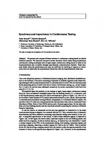
Consider the FSM (represented by the graph G(V; E )) with self-loop transitions shown in Figure 8. Suppose that vertices v0 ; v2 ; and v3 of the FSM can tolerate at most three, and v1 at most two self-loop transitions during each visit. Let transitions e10 and e11 correspond to timeouts. After either e10 or e11 is triggered, the FSM is brought into state v3 .
Considering the constrained self-loop problem, the test sequence for the graph of Figure 9 is obtained as
UIO sequences and the values of max self; dstate ver and dmin self for vertices v0 ; v1 ; v2 ; and v3 are as follows:
e0; e0; e1; e2; e10; e9; e9; e9; e12; e0; e1; e2; e2; e4; e6; e7; e11; e9; e12; e1; e3; e2; e4; e6; e6; e7; e5; e0; e1; e4; e7; e6; e7; e5; e1; e4; e8; e6; e7; e5 (7)
Vertex UIO max self dstate ver dmin self v0 e0 3 1 2 v1 e2 2 1 3 v2 e6,e7 3 2 4 v3 e9 3 1 2
containing 40 edges. Although longer than that of Figure 8, the test sequence in Figure 9 is minimum-length with the introduced selfloop constraint. During each visit to vertices v0 ; v1 ; v2 and v3 , the number of consecutive self-loop edges traversed is less than or equal to the maximum allowed number of selfloop traversals. Therefore, this test sequence is realizable in the test laboratory.
The Chinese postman method [68] when applied to the graph without any self-loop repetition constraint results in the test sequence
e0; e0; e1; e2; e2; e2; e10; e9; e9; e9; e12; e0; e1; e3; e2; e4; e6; e7; e6; e6; e7; e11; e9; e12; e1; e4; e7; e6; e7; e8; B. Research Area 2: The Controllability Problem e6; e7; e5; e0 (6) containing 34 edges. Edges used for the purpose of state Consider a testing framework where the interface I1 veri cation appear in bold. between the IUT and the (N)-layer in the System Un-
10
e7 e10
e6 e9
e8
e11
v3
e12
v2
e5
e4
e0
v0
v1
e1
e3 e2
Test sequence (34 edges) e0 e0 e1 e2 e2 e2 e10 e9 e9 e9 e12 e0 e1 e3 e2 e4 e6 e7 e6 e6 e7 e11 e9 e12 e1 e4 e7 e6 e7 e8 e6 e7 e5 e0
Fig. 8. Minimum-cost test sequence without self-loop repetition constraint. e10
v2*(2)
e5
e11
v3
v*(1) 2
e12
v0
e1
e4
v1*(2)
v1*(1)
Test sequence (40 edges) e0 e0 e1 e2 e10 e9 e9 e9 e12 e0 e1 e2 e2 e4 e6 e7 e11 e9 e12 e1 e3 e2 e4 e6 e6 e7 e5 e0 e1 e4 e7 e6 e7 e5 e1 e4 e8 e6 e7 e5
Fig. 9. Minimum-cost test sequence with self-loop repetition constraint.
der Test (SUT) [7] is not externally accessible (Figure 10). In other words, the inputs from (N+1)-layer cannot be directly applied to the IUT, nor can the outputs generated by the IUT be observed at (N+1)layer. Such an interface I1 is called semicontrollable if FSM1 can be utilized to supply inputs to the IUT. On the other hand, the tester can apply inputs to the IUT directly by using a lower tester, which exchanges N-PDUs with the IUT by using the (N-1)-Service Provider. The interface I0 between the lower tester and the IUT is therefore directly controllable.
of the IUT such that its semicontrollable portions become directly controllable, where possible. In the most general case, obtaining such a graph conversion may end up with exponentially large number of nodes. However, it is shown [23] that special considerations such as the small number of interfaces interacting with an IUT and diagnostics considerations make the problem size feasible for most practical cases. B.1 Practical Motivation
The methodology presented in [23] addresses the problem of generating optimal realizable test sequences in an environment with multiple semicontrollable interfaces. The methodology fully utilizes semicontrollable interfaces in an IUT while avoiding the race conditions. An algorithm is introduced in [23] to modify the directed graph representation
As motivation for solving the controllability problem, a real protocol is considered where an SUT's (N+1)-layer must be utilized indirectly to test certain transitions within the (N)-layer IUT. 188-220 focuses on 3 layers: Physical, Datalink, and Network. The Network layer contains an Intranet 11
SUT
PCO/IAP
FSM 1 b
c
I1
(N+1)-layer (N)-layer
Lower Tester
IUT
N-PDUs
a
d
I0
(N-1)-Service Provider
Fig. 10. Testing (N)-layer IUT with an (N+1)-layer semicontrollable interface.
sublayer. An SUT contains the (N)-layer IUT im- by the lower tester. plemented in the Datalink layer, and the Intranet sublayer, which is part of the (N+1)-layer, as shown In fact, 70% of the transitions the Class A{Type 1 Datalink Service module are based on not directly in Figure 11. controllable inputs. Without indirect testing, test In the CECOM's environment used for testing 188- coverage would be seriously limited; only approxi220 implementations, the upper layers cannot be di- mately 200 transitions out of 750 would be testable. rectly controlled. Therefore, the IUT's transitions However, by applying the technique outlined in this that are triggered by the inputs coming from the paper, over 700 of de ned transitions (>95%) can be Network layer are not directly testable. An example tested. The application of the presented technique SUT transition that causes a controllability prob- to 188-220 is described in more detail in [22]. lem is the transition t1 from the Class A{Type 1 Service Datalink module [18], [21], shown in Fig- Similar controllability problems can also be pointed ure 11. The input/event eld for this transition re- out in testing the IEEE 802.2 LLC Connection Comquires a DL Unitdata Req from the (N+1)-layer. Un- ponent [23], [36]. fortunately, the interface between the IUT and the (N+1)-layer is not directly accessible for generating B.2 Optimizing Tests with Multiple Semicontrolthis input. Initially, it appears that transition t1 is lable Interfaces untestable. To trigger this transition, which requires the (N+1)- To optimize tests with multiple semicontrollable inlayer to pass a DL-Unitdata.Req down to the (N)- terfaces, modeling SUT as a single FSM was prolayer, feedback from the (N+1)-layer must be used. posed [23], [24]. A semicontrollable interface Ii is imTo force a DL-Unitdata.Req from the (N+1)-layer, plemented as a separate FIFO bu�er. During testing, the tester sends a PL-Unitdata.Ind to the IUT (sim- a bu�er may be empty or store an arbitrary sequence ilar to the message a in Figure 10) that contains an of inputs to the IUT generated indirectly through Ii . intranet layer message telling the (N+1)-layer to re- For each Ii , we de ne variable !i that has a dislay the frame to a di�erent network node. The IUT tinct value for each permutation of inputs that the outputs this message to the (N+1)-layer (see message i-th bu�er can hold. The proposed model consists of b in Figure 10), and the (N+1)-layer FSM responds graph G (which represents the IUT's FSM) and the by outputting the desired DL-Unitdata.Req (message variables !1 ; !2 ; : : : ; !F . c in Figure 10). Finally, the datalink layer generates the desired output PL-Unitdata.Req (corresponding An FSM modeling the SUT can be obtained by exto message d in Figure 10), which can be observed panding G and !1 ; !2 ; : : : ; !F into G (V ; E ). An algorithm for converting G(V; E ) to G (V ; E ) pro0
0
0
12
0
0
0
SUT Transition
Intranet Sublayer
Input/Event
Output/Action
DL-Unitdata.Req
PL-Unitdata.Req, Start acknowledgment timer
DL-Unitdata.Req
t1
Datalink Layer
t1
A
(N+1)-layer
(N)-layer
B1
Tester’s inputs/outputs
Fig. 11. MIL-STD 188-220: Example of the controllability problem
ceeds as follows (a detailed description of the algo- Step 3|Retain only strongly connected states: rithm along with its pseudocode is available in [23], remove from V all vertices from which r cannot be reached, and remove from E all edges incident to such [24]): 0
0
0
vertices
Step 0|De nitions: Let Bi denote a sequence of inputs bu�ered at the ith semicontrollable interface. Each state v 2 V has two components: the original state v 2 V , and the current con guration of F bu�ers, i.e., v = (v; B^1 ; : : : ; B^F ). The algorithm constructs all possible bu�er con gurations with up to bi inputs bu�ered at Ii . Step 1|Initialize: r , root of G , as (r; ;; � � � ; ;) (root of G and con guration of empty bu�ers); E as empty set; V as fr g; Q, queue of vertices, as V Step 2|Repeat until Q is empty: 1. extract v = (vstart ; B^1 ; : : : ; B^F ) as rst element from Q, where (B^1 ; : : : ; B^F ) is current con guration 2. given the current vertex v = (vstart ; B^1 ; : : : ; B^F ), perform the following steps for each original outgoing edge e = (vstart ; vend ) 2 E : � create new con guration (B1 ; : : : ; BF ) based on the class of e (Figure 12): { Class 1: e is triggered by an input from and generates output(s) to an LT; { Class 2: e is triggered by an input from an LT and generates an output oq;l (bu�ered in Bq to create a new con guration) at Iq ; { Class 3: e is triggered by ap;k (extracted from Bp to create a new con guration) from Ip and generates output(s) to an LT; { Class 4: e is triggered by an input ap;k from Ip and generates an output oq;l at Iq . Apply rules for Class 3 and Class 2 to create a new con guration. � create new vertex vnew = (vend ; B1 ; : : : ; BF ) 2 V , and new edge enew = (v ; vnew ) 2 E ^1 ; : : : ; B^F ) can� include new edges in E i� inputs in (B not trigger other edges outgoing from vstart � append to Q end vertices vnew 2 V of new edges included in E 0
Based on the practical considerations discussed in [23], the algorithm can be re ned to meet the following objective: \generate a test sequence that, at any point in time, avoids storing more than one input in only one of the bu�ers (where possible)." Satisfying this objective yields a linear running time in the number of semicontrollable interfaces and the number of edges in G. If this objective cannot be satis ed, the running time grows and nondeterminism may not be avoided during testing.
0
0
0
0
0
0
0
0
0
Example :
Consider the IUT of Figure 13 which is interacting with semicontrollable FSM1 and FSM2 through the semicontrollable interfaces I1 and I2 , respectively. The IUT's FSM (represented by graph G) is described in Table I. Transition e1, triggered by input x1 from the lower tester, generates output o1;1 to FSM1. In response, FSM1 sends input a1;1 which triggers transition e3. (In general, ai;j is the expected response to oi;j .) Transition e2, which is triggered by a lower tester's input x2 , outputs o2;1 to FSM2 , which responds with input a2;1 triggering e4. Then e4 outputs o1;2 to FSM1 , which responds with a1;2 triggering e8. On the other hand, transitions e5, e6, e7, e9, and e10, can be triggered directly by the lower tester. e6, e7, e9, and e10, do not generate outputs to the semicontrollable interfaces. e5 generates output o2;2 to FSM2, which does not send any input to the IUT.
0
0
0
0
0
0
After conversion (Figure 14), each state of G is replaced with at most four related states in G corresponding to the bu�er con gurations at a semicontrollable interface. Each edge e is annotated as e:x, where x = 0; 1; 2; 3, depending on the input bu�ered in the e:x's start state, as shown in
0
0
0
0
0
0
13
Class 1:
x y
I0
IUT
Class 2:
Class 3:
FSM q
FSM p
Iq x y
I0
a p,k y
Ip
o p,l
y
IUT
I0
a p,k
IUT
Class 4b:
Class 4a:
FSM p
Ip
o q,l
FSM p
FSM q Iq
Ip o q,l
a p,k
IUT
IUT
y
Fig. 12. Classes of edges in G (dashed-lined outputs are optional). 0
SUT FSM2
FSM1 I1
Lower Tester (LT)
I2
IUT
e8
e9
B e1
e10
e5 e7
e2
e6
A
C e4 e3
Fig. 13. IUT interacting with two semicontrollable interfaces.
tions based on a protocol's timers. Our ATIRP research developed a new model for testing real-time protocols with multiple timers, which captures complex timing dependencies by using simple linear expressions involving timer-related variables. Similar dependencies, but based on arbitrary linear variables, are present in EFSM models of VHDL speci cations [69]. Uyar and Duale present algorithms for detecting [69] and removing [19], [76] such inconsistencies in VHDL speci cations. The new modeling technique combined with the inconsistency removal algorithms are expected to signi cantly shorten test C. Research Area 3: The Con icting Timers Prob- sequences without compromising their fault coverage. lem The model, speci cally designed for testing purposes, To ensure feasibility of tests in a laboratory, au- avoids performing a full reachability analysis and sigtomated test generation for network protocols with ni cantly limits the explosive growth of the number timer requirements must consider con icting condi-
Figure 14. The solid edges in Figure 14 are the mandatory edges that are incident to nodes that correspond to the case where both bu�ers are empty; the dashed-line edges are the ones that can be traversed only when either bu�er contains an input. Due to the practical diagnostic considerations [23], we prefer testing edges when no inputs are bu�ered in semicontrollable interfaces. The Aho et al. [1] optimization technique gives the minimum-length test sequence for G shown in Table II. Steps with ( ) indicate that an edge is tested in this step. Note that, for simplicity, the UIO sequences [58] are not included in this sequence. 0
!
14
and :. Suppose that a speci cation contains transitions with time conditions of a form \if �" for some time formula �. It is clear that there may exist infeasible paths in an FSM modeling a protocol, if two or more edges in a path have inconsistent conditions. For example, for transitions e1 : if (Tj ) then f'1 g and e2 : if (:Tj ) then f'2 g, a path (e1 ; e2 ) is inconsistent unless the action of '1 in e1 sets Tj to false (which happens when timer tmj expires in transition e1 ). The methodology presented in this paper is expected The solution to the above problem is expected to to detect transfer and output faults [45], where an allow generating low-cost tests free of such con icts. IUT moves into a wrong state (a state other than the one speci ed) or generates a wrong output (an 188-220's Datalink Layer Estelle speci cation de nes output other than the one speci ed) to a given in- several timers that can run concurrently and afput, respectively. The detection of transfer faults can fect the protocol's behavior. For example, BUSY signi cantly be improved by using the well-known and ACK timers may be running independently in state veri cation methods such as UIO sequences, FRAME BUFFERED state. If either timer is runcharacterization sets, or distinguishing sequences. ning, a bu�ered frame cannot be transmitted. If These techniques should be applied while generating ACK timer expires while BUSY timer is not runa minimum-cost test sequence from the nal con ict- ning, a bu�ered frame is retransmitted. If, however, free graph. ACK timer expires while BUSY timer is running, no output is generated. Besides Estelle speci cations, The proposed solution is likely to have a broader feasibility constraints related to multiple concurrent application due to a proliferation of protocols with timers are also of special concern for speci cations in real-time requirements. The functional errors in such SDL. protocols are usually caused by the unsatis ability of time constraints and (possibly con icting) conditions The con icting timers problem is a special case of involving timers; therefore, signi cant research is re- the feasibility problem of test sequences, which is an quired to develop e�cient algorithms for test genera- open research problem for the general case [27], [67]. tion for such protocols. Our methodology is expected However, there are two simplifying features of the to contribute towards achieving this goal. The pre- con icting timers problem: (1) timer-related variliminary results are reported in [26]. ables are linear, and (2) the values of time-keeping variables implicitly increase with time. Considering In the test cases delivered to CECOM (see Sec- these features makes it possible to nd an e�cient tion VIII), con icting conditions based on 188-220's solution to this special case. timers are resolved by manually expanding EFSMs based on the set of con icting timers. This procedure results in test sequences that are far from minimum- C.1 General approach length. The technique presented here allows us to automatically generate con ict-free test sequences for The goal of the presented technique is to achieve the 188-220. following fault coverage: cover every feasible state transition in the speci cation at least once. Suppose that a protocol speci cation de nes a set During thede ned of a system with multiple timers, of timers K = ftm1 ; : : : ; tmjK jg, such that a timer when a nodetesting v is visited, e�cient test sequence p tmj may be started and stopped by arbitrary tran- should either (1) traverse an as self-loops (i.e., sitions de ned in the speci cation. Each timer tmj transitions that start and end many the same state) as can be associated with a boolean variable Tj whose possible before a timeout or (2)inleave vp immediately value is true if tmj is running, and false if tmj is through a non-timeout transition. Once the maxnot running. Let � be a time formula obtained from imum allowable number of self-loops are traversed, variables T1 ; : : : ; Tk by using logical operands ^, _, a test sequence may leave v through any outgoing p
of test scenarios. These goals are achieved by incorporating certain rules for the graph traversal without reducing the set of testable transitions. The technique also models a realistic testing framework in which each I/O exchange takes a certain time to realize, and a tester has an ability to turn timers on and o� in arbitrary transitions and to algorithmically nd proper timeout settings.
15
transition. Such an approach does not let perform VII. Software for Automated Test full reachability analysis; however, it can be shown Generation that considering only the above two cases is su�cient to include at least one feasible path for each transi- The process of generating tests involved the develoption provided such a feasible path is not prohibited ment of two systems of software: (1) efsm2fsm -rcpt, and (2) INDEEL. These two systems are now deby the original speci cation. scribed in turn. Suppose that there are 15 untested self-loops (each requiring 1 sec to test) in state v57 , and that, when the test sequence visits v57 , the earliest timer to ex- A. efsm2fsm-rcpt pire is tm4 , with 10.5 sec remaining until its timeout. In this example, the test sequence will either leave Figure 15 depicts the major software components v57 immediately or traverse 10 of the untested self- that were developed to generate test sequences from loops. Suppose that the latter option is chosen and, an EFSM [25]. The software contains two packages: later during the test sequence traversal, v57 is visited (1) efsm2fsm , and (2) rcpt. The former was designed again with tm2 leaving 3.1 sec until the earliest time- and implemented UD. The latter was based on the out. In this case, 3 more untested self-loops of v57 software written atatCCNY, originally was able can be covered by the test sequence. Traversal will to handle graphs of at most which 100 transitions in a plain continue until all of the v57 's self-loops are tested. input/output format, without any of the additional In more complicated cases, in addition to the afore- parameters speci cally required for 188-220B tests. mentioned timing constraints, traversal of a self-loop This component was enhanced to generate tests for requires that its associated time condition be satis- 188-220B for a proprietary CECOM's format. Also, ed, i.e., certain timers be active (or, similarly, other the software was signi cantly redesigned to process timers be inactive). These time conditions will also large graphs (1000s of transitions), which enabled its be taken into account while selecting which self-loops application to more complex real-life protocols. to traverse. In the above example, if 6 or more selfloops of v57 have `tm4 not running' as their time condition, the test sequence, which tries to execute 10 A.1 efsm2fsm of the untested self-loops, will cause a timer con ict due to the unsatis ability of the time condition. efsm2fsm takes a protocol's EFSM representation as and performs its expansion to an FSM. Each In general, the goal of an optimization is to gener- input transition is associated with the following ate a low-cost test sequence that follows the above EFSM's parameters: transition name in the Estelle speci guidelines, satis es time conditions of all composite cation, transition start and end states, edges and is not disrupted by timeout events during input and output description, names, numerical values specifytraversal (i.e., contains only feasible transitions). ing the corresponding elds in 188-220B's PDUs, and Similar inconsistencies, but based on arbitrary lin- changes in the variables' values (i.e., start and end ear variables, are present in EFSMs modeling VHDL con gurations. To express the start and end conspeci cations. ATIRP researchers Uyar and Duale gurations, a simple notation was de ned. In the presented algorithms for detecting [69] and remov- potential future work on this package, it is essential ing [70] inconsistencies in VHDL speci cations. Re- that this notation be replaced with a di�erent one, cent research in UD and CCNY focused on adapting which should be more expressive and exible. these algorithms to detecting and removing inconsis- To facilitate creating the input to efsm2fsm , spontatencies caused by a protocol's con icting timers. The neous transitions are allowed to be speci ed in the insoftware implementation of these algorithms devel- put EFSM. These transitions are then concatenated oped within ATIRP is described in the next section. with regular transitions (i.e., triggered by an external input) to eliminate spontaneous transitions from the resulting FSM. This procedure can be brie y de16
scribed as follows. Suppose that in a path t t1 t2 t v v0 ! v1 ! v2 : : : vi?1 ! vi : : : vn?1 ! n i
n
Note that the original EFSM to FSM conversion technique implemented should be replaced by the application of the inconsistency elimination algorithms implemented in INDEEL (see Section VII-B). Using INDEEL to eliminate inconsistencies results in a con ict-free EFSM that is signi cantly smaller than the FSM.
(8)
where vi and ti denote a state and a transition, respectively, t1 is regular and t2 ; : : : ; tn are spontaneous. Then transitions t1 ; : : : ; tn are concatenated into a single transition t1;n from state v0 to state vn . Their inputs, outputs, and other parameters are combined and associated with transition t1;n . States A.2 rcpt v2 ; : : : ; vn?1 are marked as temporary, and subsequently removed from the FSM along with their out- The FSM produced by efsm2fsm is then fed to rcpt , which builds a corresponding directed graph repregoing transitions. sentation G. Then, network ow techniques are apAfter the expansion to an FSM, transitions that are plied to nd a rural symmetric augmentation of G equivalent from a testing point of view could be iden- as G . Finally, rcpt nds an Euler tour of G , and ti ed, leading to a minimum-cost test sequence cov- outputs to a le a resulting test sequence conforming ering at least one transition from each equivalence to the CECOM's proprietary format. class. However, building such a test sequence is NP-hard [25]. Therefore, simple heuristics bringing Suppose that protocol.fsm is an input le containing about 20%-30% reduction in the number of transi- a protocol's FSM. Then the following command runs the package: tions were implemented. 00
It is possible to manually prepare the input le for the package such that an EFSM's states are divided into two groups: (1) states with no inputs bu�ered, and (2) states with one input bu�ered at a semicontrollable interface. Then semicontrollable interfaces can be utilized for certain simpli ed cases such as using the 188-220B Intranet layer for indirect testing of 188-220B Datalink layer (in these tests, only one semicontrollable interface is used with a small number of semicontrollable inputs). A self-loop repetition constraint can be taken into account for the case of self-loop state veri cation sequences.
00
rcpt [-cecom/-plain ] protocol.fsm output le
where plain option refers to a plain input/output le format. protocol.fsm le in plain format can be prepared manually. The cecom option selects test generation in the CECOM format. In this case, the input le protocol.fsm should be generated by the efsm2fsm package. The tests are stored in the number of les named protocol.i , where i is the index of a test group. B. INDEEL: Software for Inconsistency Detection and Elimination
To run the package for a protocol's EFSM speci ed in le protocol.efsm , the following command must be Feasible test sequence generation is essential for assuring the proper operation and interoperability of used: di�erent components in computer and communicaefsm2fsm protocol.efsm [-options] tion systems. The use of formal description languages such as VHDL and Estelle enable the precise producing two les protocol.fsm and protocol.stat . description of such systems to minimize the impleThe former contains the output FSM. All informa- mentation errors due to misinterpretations. Howtion associated with transitions in the input EFSM ever, the speci cations written in VHDL and Estelle is preserved. This enables the rcpt package to pop- are often extended nite-state machines (EFSMs), ulate the elds de ned in the CECOM's proprietary making the automated test generation a more comformat for test sequences. The latter le contains plex task due to the inconsistencies among the action statistics such as the number of states and transitions and condition variables [19]. in the EFSM/FSM, and the percentage e�ectiveness of the reduction heuristics. Within ATIRP, we studied the problem of generat17
ing feasible test sequences for the EFSM by analyzing the interdependencies among the action and condition variables of the EFSM models. In the earlier phases of this research, action and condition inconsistencies in the EFSM models were de ned [75], [76]. It has been shown that once the inconsistencies are eliminated, the existing nite-state machine (FSM)based test generation methods can be used to generate feasible test sequences from the resulting consistent EFSM graphs.
and the nal output graphs are provided as les. INDEEL starts its analysis by considering the action inconsistencies; it then proceeds to the detection and elimination of the condition inconsistencies (if any). During the analysis of the action inconsistencies, INDEEL constructs a set of Action Update Matrix (AUM) pairs for each node. The AUM pairs represent the e�ects of the actions of the traversed edges leading to a given node vi . Similarly, the accumulated di�erent conditions of the paths leading to vi can be represented as a set of Accumulated Condition Matrix (ACM) triplets containing the coe�cients, operators, and constants of the edge conditions.
The basic concepts for the inconsistency elimination algorithms were outlined in [76], which were later were generalized to include graphs with loops [71]. The formal descriptions of the inconsistency detection and elimination algorithms have been given To reduce the space complexity, during the AUM in [19]. and ACM constructions, the software uses a single A software package, called INDEEL (INconsistencies matrix called path matrices in which the numbers DEtection and ELimination), has been implemented of the edges in the paths from the initial node to vi at CCNY based on the inconsistency elimination al- are stored. gorithms. As part of the ongoing collaboration between the CCNY and the UD, the application of INDEEL implements a two-phase modi ed breadththese algorithms was extended to generate test se- rst graph traversal, called P1-MBF and P2-MBF, quences for the protocols with con icting timers such to handle the detection of the action inconsistencies. P1-MBF is the main graph traversal from which P2as 188-220. MBF may be invoked multiple times. During the INDEEL contains 13,000+ lines of C code. As its condition inconsistency detection phase, the graph input, the software reads a user speci ed le con- is traversed in a regular depth- rst (DF) manner. taining the description of an EFSM graph with the The software: efsm2fsm -rcpt, and (2) INDEEL were following properties: used to help generate tests for 188-220 that have been delivered to CECOM. This technology transfer is de� The speci cation consists of a single process and scribed in the next section. thus there are no communicating EFSMs. � If the speci cation contains function calls, they can VIII. ATIRP to CECOM Technology be described within the process with a simple transTransfer Results formation. � Pointers, recursive functions, and syntactically Using research results from Section VI, and software endless loops are assumed not to be present in the as described in Section VII-B, UD and CCNY collabspeci cation. orated with CECOM to generate tests for the SAP � All conditions and actions are linear. components of 188-220's Data Link Layer Class A. Class A stations implement Type 1 (UnacknowlINDEEL uses an iterative approach: every time an edged and Coupled Acknowledged Datalink Connecaction or condition inconsistency is detected and tionless) Service, with the original EFSM consisting eliminated, an intermediate output graph is gener- of 1 state and 15 transitions. Based on the Class A ated in a le, using the same format as in the in- SAP functionalities, the original EFSM was divided put le. This intermediate output le then becomes into three EFSMs modeling: (1) general behavior the new input le to INDEEL for continued analysis. of the SAP component interacting with two destiThis iterative procedure is repeated until the graph nations, (2) datalink precedence, and (3) an IUT's becomes free of inconsistencies. The intermediate 18
behavior when interacting with up to sixteen destinations. Since the total number of states/transitions that would be obtained after full expansion to a pure FSM was infeasibly large, each of the three EFSMs was expanded to a form closer to a pure FSM, but still containing some extensions.
Estelle transition(s), and the appropriate section(s) from the 188-220 o�cial document. In 1998, the work on test generation expanded to include Class C. Class C also allows Type 1 Service as in Class A, but it additionally de nes Type 4 (Decoupled Acknowledged Connectionless) Service. As in the case of Class A, three EFSMs were used to generate three sets of tests for each Class C service. The sizes of the EFSMs and the corresponding minimumlength tests are shown in Table III. For example, the general behavior tests set for Class C Type 4 Service was based on an EFSM of 235 states and 925 transitions. The minimum-length test sequence generated for this machine consists of 2,803 input/output pairs. These tests have been delivered to CECOM.
To avoid state explosion problem, each expanded EFSM focused on certain protocol functionalities while restricting others. For example, in 188-220, a sender can interact with up to sixteen destinations, each of which may be free or busy. In general behavior tests, destinations are allowed to transit between free or busy mode, but the sender is restricted to communicate with at most two of them. In multidestination tests, the sender communicates with up to sixteen destinations, which are forced to remain In the nal phase of ATIRP, we have been invesin free mode at all times. tigating test generation for 188-220 Class B which Each expanded EFSM was then used in automated includes Types 1,3, and 2 service. Class B is much test generation. Table III shows the sizes of the ex- more complex than Classes A and C, and involves panded EFSMs and the tests that were generated generating problems for reliable connection-oriented from them. For example, the precedence tests set service test case generation. for Class A{Type 1 Service was based on an expanded EFSM of 303 states and 401 transitions. The The implementations of 188-220 from several manminimum-length test sequence generated for this ma- ufacturers are being tested at CECOM. The tests chine consists of 1,316 input/output pairs covering generated by the UD and CCNY team have uncovevery transition in the expanded EFSM at least once. ered several implementation errors, including lack of mandatory capabilities in Datalink layer, and probIn 1997, these Class A tests were delivered to CE- lems with multi-hop Intranet Relaying. COM for use in its 188-220 testing facility. Figure 16 shows a sample of the delivered test scripts. IX. Conclusions: Improvements to Protocol Development Process The gure depicts the test group #92 from Datalink Class A{Type 1 service tests. Each test group is A. Integration of Estelle into System Development a subsequence of a full test sequence that starts and ends in the initial state. In the rst step, the technique of utilizing semicontrollable interfaces pre- Traditional sequential process of system development sented in Section VI-B is used. The lower tester is known to be ine�cient since it allows unnecessends a packet with three destination addresses: sary duplication and does not facilitate tracking of IUT addr, des addr 1, and des addr 2. The setting rapidly changing technology. With 188-220 as a Relay=Yes in the INTRANET clause tells the rst critical component, a synergistic framework for C 4 I addressee, i.e., the IUT, to relay the packet to the two (Command, Control, Communications, Computers, remaining addressees. As a result, the IUT sends a and Intelligence) systems development has been espacket with its address as a source, and des addr 1 tablished [20] (Figure 17). It combines several parand des addr 2 as destinations, as if it were origi- allel activities: developing protocol standards and nated by the IUT's Intranet Layer. In the second speci cations, formally specifying protocols in Esand third steps, the IUT's packet sent in the rst telle, building conformance tester hardware and softstep is acknowledged by des addr 2 and des addr 1, ware, \ eld testing", modeling and simulation, as respectively. Each test step is further annotated with well as resolving and documenting the solutions to the test description, the number of the corresponding standards-related technical issues by the Joint CNR 19
Working Group. (WG participants include repre- C. Observations on Applicability of Formal Methods sentatives from DoD services/agencies, industry, and academia.) As concluding remarks for this paper, we report the following observations based on our experience durUsing formal methods as part of this process helped ing the formal speci cation and test generation for create a high quality protocol standard, which is ro- 188-220. bust and e�cient. Due to the structured nature of Estelle, the speci cation process progressed at an ac- To develop an Estelle formal speci cation of a procelerated pace compared to the other standards. 188- tocol, we must not only de ne its architecture and 220 was completed on time, setting a rare example interface components (e.g., as in Figures 4 and 5 for in the protocol standards arena. 188-220), but we must also carefully specify the behavior of each module of these components. This Since it is relatively easier to extract modeling infor- de nition, through the creation of EFSMs, mation from a formal speci cation, the researchers is the mostachieved di�cult and time-consuming step of creat UD and CCNY were able to solve a number of ating a formal speci cation. A syntax-directed editheoretical problems, which resulted in the devel- tor improves the readability for who are not opment of new testing methodologies. By applying FDT-trained; it also is useful intesters writing these new results, the conformance tests for 188-220 speci cations. Moreover, the modeling andnon-trivial speci cawere generated while the protocol was still evolving. tion languages, such as SDL [29], [30] and UML Performing initial conformance tests on prototypes enjoy widespread industrial popularity, partially[54], due uncovered several interoperability errors early in the to their standard graphical representation. Theredevelopment process. Following this success of the fore, it will be a natural extension for Estelle to in188-220 development, the synergistic e�orts to dea graphical editor [60]. Once all states and velop C 4 I systems with the help of formal methods clude transitions of a protocol (including inputs and outserves as a model for DoD standards process and de- puts) are nalized, the writing of the Estelle code velopment for the future [20]. itself is fast and straightforward. Since 188-220 is a multilayer, multifunction protocol of a considerable size and complexity, manual generB. Advantages of Formal Methods in Eliminating ation of conformance test sequences would be both Protocol Errors ine�cient and ine�ective. As seen from Table III, the tests already delivered to CECOM contain approximately 10,000 test steps. It is clear that manually The di�culties of describing protocol operations generating test sets of this size from the protocol texwith clarity, precision, and consistency by using a tual description is not a trivial task. natural language are illustrated by the examples in Section V-B. In addition to the vagueness intro- A number of conformance test generation techniques duced by a natural language description, ambigui- have been proposed [1], [7], [9], [50], [57], [59], [63], ties and contradictions are di�cult to detect when [66], each of which is expected to give better rerelated protocol functionalities are de ned in di�er- sults for a certain class of protocol speci cations ent document sections separated by several pages of depending on the nature and size of the protocol. unrelated text. Such problems are eliminated in a The experience obtained in generating tests for 188formal Estelle speci cation. All actions in a partic- 220 suggests that to successfully test today's comular context are de ned in one place within the Es- plex protocols by using formal methods, an ideal test telle speci cation. The speci cations make the con- generation tool should support multiple test generditions for state transitions explicit through Estelle ation techniques [45]. They can range from Postconstructs. Indeed, the very process of creating these man tours [1] or fault-oriented tests [78], [80] for constructs enables formal speci ers to detect some of mid-size protocols when the number of states ranges these types of ambiguities which are di�cult to see on the order of thousands, to guided random walk in normal reading of a document written in English. approaches [43], [81] for larger protocols when the 20
number of states ranges in the tens of thousands.
[4] B. Baumgarten, H.-J. Burkhardt, and A. Giessler, editors. Proc. IFIP Int'l Workshop Test. Communicat. Syst. (IWTCS), Darmstadt, Germany, Sept. 1996. Boston, MA: Kluwer Academic Publishers. [5] A. Bhattacharyya. Checking Experiments in Sequential Machines. Wiley & Sons, New York, NY, 1989. [6] J. Bi and J. Wu. Application of a TTCN-based conformance test environment to the Internet email protocol. In Kim et al. [41], 324{330. [7] B. S. Bosik and M. U. Uyar. FSM-based formal methods in protocol conformance testing: from theory to implementation. Comput. Networks & ISDN Syst., 22(1):7{34, Sept. 1991. [8] J. Bredereke and R. Gotzhein. Speci cation, detection, and resolution of IN feature interactions with Estelle. Proc. IFIP Formal Desc. Tech. (FORTE), 376{378. Chapman & Hall, 1995. [9] E. Brinksma. A theory for the derivation of tests. Proc. IFIP Protocol Specif., Test., & Verif. (PSTV). Amsterdam: North-Holland, 1988. [10] S. Budkowski, A. Cavalli, and E. Najm, editors. Proc. IFIP Joint Int'l Conf. FORTE/PSTV, Paris, France, Nov. 1998. Boston, MA: Kluwer Academic Publishers. [11] S. Budkowski and P. Dembinski. An introduction to Estelle: A speci cation language for distributed systems. Comput. Networks & ISDN Syst., 14(1):3{24, 1991. [12] S. Budkowski, S. Fischer, and R. Gotzhein, editors. Proc. Int'l Workshop FDT Estelle, Evry, France, Nov. 1998. Evry, France: Institut National des T�el�ecommunications (INT). [13] R. Burch, P. Amer, and S. Chamberlain. Performance evaluation of MIL-STD 188-220A: Interoperability standard for digital message transfer device subsystems. Proc. IEEE MILCOM, San Diego, CA, Nov. 1995. [14] O. Catrina, E. Lallet, and S. Budkowski. Automated implementation of the Xpress Transport Protocol (XTP) from an Estelle speci cation. Electronic J. Networks & Distrib. Process., (7):3{19, Dec. 1998. [15] K. T. Cheng and A. S. Krishnakumar. Automatic generation of functional vectors using the extended nite state machine model. ACM Trans. Design Automation of Electronic Syst.,
The state explosion problem has been a major issue for generating FSM models out of EFSM representations of protocols [15], [56], [79], [80]. One common procedure for converting EFSMs into FSMs simultaneously performs reachability analysis and online minimization [15], [44]; this conversion is based on combining equivalent states [58] using bisimulation equivalence [51]. Another approach proposes the elimination of inconsistencies in EFSM models [69], [70]. E�cient algorithms such as these should be implemented in any test generation tool using FSM models. If the nal FSM model is not con ned to a manageable size, the test sequences generated from it will be infeasibly long regardless of the test generation method. Finally, a test house may require its own proprietary format for the executable tests. Although TTCN is accepted as input by many test tools, a proprietary test format may be preferable for a given protocol if this format is more readable by testers, or is simpler to parse by software tools. The output of a test generation tool should be easily custom-tailored for a particular format, possibly by using simple application generators.
X. Acknowledgments The authors thank Samuel Chamberlain of ARL; Ted Dzik and Ray Menell of CECOM; and Mike McMahon and Brian Kind of ARINC, Inc. for their collaboration in this research.
REFERENCES [1] A. V. Aho, A. T. Dahbura, D. Lee, and M. U. Uyar. An optimization technique for protocol conformance test generation based on UIO sequences and rural Chinese postman tours. IEEE Trans. Commun., 39(11):1604{1615, Nov. 1991. [2] P. D. Amer, G. Burch, A. S. Sethi, D. Zhu, T. Dzik, R. Menell, and M. McMahon. Estelle speci cation of MIL-STD 188-220A DLL. Proc. IEEE MILCOM, Oct. 1996. [3] P. D. Amer, M. A. Fecko, A. S. Sethi, M. U. Uyar, T. J. Dzik, R. Menell, and M. McMahon. Using Estelle to evolve MIL-STD 188-220. In Budkowski et al. [12], 55{58. 21
[16] [17] [18] [19]
[20] [21]
[22]
[23] [24] [25] [26]
[27]
1(1):57{79, Jan. 1996. S.-K. Cheong, K.-H. Lee, and T.-W. Jeong. The analysis of integrating test results for ATM switching systems. In Baumgarten et al. [4], 83{ 89. J. Y. Choi and B. K. Hong. Generation of conformance test suites for B-ISDN signalling relevant to multi-party testing architecture. In Baumgarten et al. [4], 316{330. DoD. Military Standard|Interoperability Standard for Digital Message Device Subsystems (MIL-STD 188-220B), Jan. 1998. A. Duale and U. Uyar, Generation of feasible test sequences for EFSM models. In H. Ural, R. Probert, and G. v. Bochmann, eds, Proc. IFIP Int'l Conf. Testing o Communicating Systems, TestCom, Ottawa, Sept. 2000, 91-109. T. Dzik and M. McMahon. MIL-STD 188-220A evolution: A model for technical architecture standards development. Proc. IEEE MILCOM, Monterey, CA, Nov. 1997. M. A. Fecko, P. D. Amer, A. S. Sethi, M. U. Uyar, T. Dzik, R. Menell, and M. McMahon. Formal design and testing of MIL-STD 188220A based on Estelle. Proc. IEEE MILCOM, Monterey, CA, Nov. 1997. M. A. Fecko, M. U. Uyar, P. D. Amer, and A. S. Sethi. Using semicontrollable interfaces in testing Army communications protocols: Application to MIL-STD 188-220B. Proc. IEEE MILCOM, Atlantic City, NJ, Oct. 1999. M. A. Fecko, M. U. Uyar, A. S. Sethi, and P. D. Amer. Issues in conformance testing: Multiple semicontrollable interfaces. In Budkowski et al. [10], 111{126. M. A. Fecko, M. U. Uyar, A. S. Sethi, and P. D. Amer. Conformance testing in systems with semicontrollable interfaces. Annals of Telecommun., 55(1):70{83, Jan. 2000. M. A. Fecko. Timing and control issues in conformance testing of protocols PhD Dissertation, CISC Dept., Univ. of Delaware, 1999. M. A. Fecko, M. U. Uyar, A. Y. Duale, and P. D. Amer. Test generation in the presence of con icting timers. In H. Ural, R. Probert, and G. v. Bochmann, eds, Proc. IFIP Int'l Conf. Testing o Communicating Systems, TestCom, Ottawa, Sept. 2000. S. Fujiwara, G. v. Bochmann, F. Khendek, M.
[28] [29] [30] [31]
[32] [33]
[34] [35] [36] [37] [38] [39]
[40] 22
Amalou, and A. Ghedamsi. Test selection based on nite state models. IEEE Trans. Software Eng., 17(6):591{603, Jun. 1991 R. Gecse. Conformance testing methodology of Internet protocols: Internet application-layer protocol testing|HTTP. In Petrenko and Yevtushenko [55], 35{48. D. Hogrefe. Validation of SDL systems. Comput. Networks & ISDN Syst., 28(12), 1996. Int'l Telecomm. Union, Geneva, Switzerland. ITU Recommendation Z100: Speci cation and Description Language (SDL), 1989. ISO, Information Processing Systems|OSI, Geneva, Switzerland. ISO/IEC International Standard 8571-1: File Transfer, Access and Management|Part 1: General introduction, 1988. ISO, Information Processing Systems|OSI. ISO International Standard 9074: Estelle|A Formal Description Technique Based on an Extended State Transition Model, 1989. ISO, Information Technology|OSI, Geneva, Switzerland. ISO/IEC International Standard 13712-3: Remote Operations: OSI realizations|Remote Operations Service Element (ROSE) protocol speci cation, 1995. ISO, Information Technology|OSI, Geneva, Switzerland. ISO/IEC International Standard 8327-1: Connection-oriented Session Protocol| protocol speci cation, 1996. ISO, Information Technology|OSI, Geneva, Switzerland. ISO/IEC International Standard 10026-3: Distributed Transaction Processing| Part 3: Protocol speci cation, 1998. ISO/IEC. International Standard ISO/IEC 8802-2, ANSI/IEEE Std. 802.2, 2nd edition, Dec. 1994. ITU. Recommendation Q.2110: Service Speci c Connection-Oriented Protocol (SSCOP). A. Jirachiefpattana and R. Lai. Uncovering ISO ROSE protocol errors using Estelle. Comput. Stand. & Interf., 17(5-6):559{583, 1995. S. Kang, Y. Seo, D. Kang, M. Hong, J. Yang, I. Koh, J. Shin, S. Yoo, and M. Kim. Development and application of ATM protocol conformance test system. Proc. IFIP Int'l Workshop Test. Communicat. Syst. (IWTCS), Budapest, Hungary, Sept. 1999. T. Kato, T. Ogishi, A. Idoue, and K. Suzuki. Intelligent protocol analyzer with TCP behav-
[41] [42] [43]
[44] [45] [46] [47] [48] [49]
[50] [51] [52] [53]
ior emulation for interoperability testing of TCP/IP protocols. Proc. IFIP Joint Int'l Conf. FORTE/PSTV, 449{464, Osaka, Japan, Nov. 1997. M. Kim, S. Kang, and K. Hong, editors. Proc. IFIP Int'l Workshop Test. Communicat. Syst. (IWTCS), Cheju Island, Korea, Sept. 1997. Boston, MA. Z. Kohavi. Switching and Finite Automata Theory. McGraw-Hill, New York, NY, 1978. D. Lee, K. K. Sabnani, D. M. Kristol, and S. Paul. Conformance testing of protocols speci ed as communicating FSMs|a guided random walk approach. IEEE Trans. Commun., 44(5), May 1996. D. Lee and M. Yannakakis. Online minimization of transition systems. Proc. 24th Annual ACM, Victoria, Canada, 1992. D. Lee and M. Yannakakis. Principles and methods of testing nite state machines|a survey. Proc. IEEE, 84(8):1090{1123, Aug. 1996. D. Y. Lee and J. Y. Lee. Test generation for the speci cation written in Estelle. Proc. IFIP Protocol Specif., Test., & Verif. (PSTV), Stockholm, Sweden, June 1991. D. Y. Lee and J. Y. Lee. A well-de ned Estelle speci cation for the automatic test generation. IEEE Trans. Comput., 40(4), Apr. 1991. J. K. Lenstra and A. H. G. Rinnooy Kan. On general routing problems. Networks, 6:273{280, 1976. H. Li, P. Amer, and S. Chamberlain. Estelle speci cation of MIL-STD 188-220A: Interoperability standard for digital message transfer device subsystems. Proc. IEEE MILCOM, San Diego, CA, Nov. 1995. R. E. Miller and S. Paul. On the generation of minimal-length conformance tests for communication protocols. IEEE/ACM Trans. Networking, 2(1):116{129, Feb. 1993. R. Milner. Communication and Concurrency. Prentice-Hall, Englewood Cli�s, NJ, 1989. P. Mondain-Monval. ISO Session Service speci cation in Estelle. Technical Report SEDOS Rep. 70, ESPRIT Project, Nov. 1986. C. Negulescu and E. Borcoci. SSCOP protocol throughput evaluation|simulation based on Estelle speci cation. In Budkowski et al. [12], 75{98.
[54] Object Management Group, Framingham, MA. OMG Standard: Uni ed Modeling Language (UML) 1.1, 1997. [55] A. Petrenko and N. Yevtushenko, editors. Proc. IFIP Int'l Workshop Test. Communicat. Syst. (IWTCS), Tomsk, Russia, Sept. 1998. Boston, MA: Kluwer Academic Publishers. [56] D. H. Pitt and D. Freestone. The derivation of conformance tests from LOTOS speci cations. IEEE Trans. Softw. Eng., 16(12):1337{ 1343, 1990. [57] J. Romijn and J. Springintveld. Exploiting symmetry in protocol testing. In Budkowski et al. [10], 337{351. [58] K. K. Sabnani and A. T. Dahbura. A protocol test generation procedure. Comput. Networks & ISDN Syst., 15:285{297, 1988. [59] B. Sarikaya, G. von Bochmann, and E. Cerny. A test design methodology for protocol testing. IEEE Trans. Softw. Eng., 13(5):518{531, May 1987. [60] J. Templemore-Finlayson, J l. Ra�y, P. Kritzinger, and S. Budkowski. A graphical representation and prototype editor for the formal description technique Estelle. In Budkowski et al. [10], 37{55. [61] R. Tenney. A tutorial introduction to Estelle. Technical Report 88-1, Univ. of Mass, Boston, June 1988. [62] J. Thees. Protocol implementation with Estelle|from prototypes to e�cient implementations. In Budkowski et al. [12], 187{193. [63] J. Tretmans. Conformance testing with labelled transitions systems: Implementation relations and test generation. Comput. Networks & ISDN Syst., 29(1):49{79, 1996. [64] K. Turner. Formal Description Techniques. North-Holland, Amsterdam, 1989. [65] H. Ural and B. Yang. A test sequence selection method for protocols speci ed in Estelle. Technical Report TR-88-18, Univ. of Ottawa, June 1988. [66] H. Ural and B. Yang. A test sequence selection method for protocol testing. IEEE Trans. Commun., 39(4), 1991. [67] H. Ural. Formal methods for test sequence generation. Computer Communications, 15(5):311325, Jun. 1992. 23
[68] M. U. Uyar and A. T. Dahbura. Optimal test sequence generation for protocols: the Chinese postman algorithm applied to Q.931. Proc. IEEE GLOBECOM, 68{72, Dec. 1986. [69] M. U. Uyar and A. Y. Duale. Modeling VHDL speci cations as consistent EFSMs. Proc. IEEE MILCOM, Monterey, CA, Nov. 1997. [70] M. U. Uyar and A. Y. Duale. Removal of inconsistencies in VHDL speci cations. Proc. US Army Research Lab ATIRP Conf., College Park, MD, Feb. 1998. [71] M. U. Uyar and A. Y. Duale. Conformance tests for Army communication protocols. Proc. US Army Research Lab ATIRP Conf., College Park, MD, Mar. 2000. [72] M. U. Uyar, M. A. Fecko, A. S. Sethi, and P. D. Amer. Minimum-cost solutions for testing protocols with timers. Proc. IEEE Int'l Performance, Comput., & Commun. Conf. (IPCCC), 346{354, Phoenix, AZ, Feb. 1998. [73] M. U. Uyar, M. A. Fecko, A. S. Sethi, and P. D. Amer. Testing protocols modeled as FSMs with timing parameters. Comput. Networks, 31(18):1967{1988, Sept. 1999. [74] M. U. Uyar and M. H. Sherif. Protocol modeling for conformance testing: Case study for the ISDN LAPD protocol. AT&T Technical J., 69(1), Jan. 1990. [75] M. U. Uyar and A. Y. Duale, \Modeling VHDL Speci cations as Consistent EFSMs," Proc. IEEE MILCOM, Monterey, CA, Oct. 1997, 740744. [76] M. U. Uyar and A. Y. Duale. Resolving inconsistencies in VHDL Speci cations. Proc. IEEE MILCOM, Atlantic City, NJ, Oct. 1999, No. 5.1.3. [77] E. V�azquez, P. Sandoval, M. Sedano, and J. Vinyes. Automatic implementation of TP4/IP with an Estelle workstation| development methodology and performance evaluation. Proc. IFIP Protocol Specif., Test., & Verif. (PSTV), 125{139. Amsterdam: North-Holland, 1992. [78] G. von Bochmann, A. Das, R. Dssouli, M. Dubuc, A. Ghedamsi, and G. Luo. Fault models in testing. Proc. IFIP Int'l Workshop Protocol Test Syst. (IWPTS), 17{30. Amsterdam: North-Holland, 1992. [79] C. J. Wang and M. T. Liu. Axiomatic test se-
[80] [81] [82] [83] [84]
24
quence generation for extended nite state machines. Proc. 12th Conf. Distrib. Comput. Syst., 252{259, 1992. C. J. Wang and M. T. Liu. Generating test cases for EFSM with given fault models. Proc. IEEE INFOCOM, 774{781, 1993. C. West. Protocol validation by random state exploration. Proc. IFIP Protocol Specif., Test., & Verif. (PSTV). Amsterdam: North-Holland, 1986. J. Wytr�ebowicz and P. Roli�nski. Analysis tools for Estelle speci cations. In Budkowski et al. [12], 141{155. XTP Forum, Santa Barbara, CA. Xpress Transport Protocol Speci cation, Rev. 4.0, 1995. S. Yoo, L. Collica, and M. Kim. Conformance testing of ATM Adaptation Layer protocol. In Baumgarten et al. [4], 237{252.
TABLE I Inputs and outputs for the edges of Figure 13. A?x denotes receiving input x from A. B !y denotes sending output y to B .
Edge e1 e2 e3 e4 e5
Input LT ?x1 LT ?x2
FSM1 ?a1;1 FSM2 ?a2;1 LT ?x5
Output FSM1 !o1;1 FSM2 !o2;1 LT !y3 FSM1 !o1;2 FSM2 !o2;2
Edge e6 e7 e8 e9 e10
Input LT ?x6 LT ?x7
FSM1 ?a1;2 LT ?x9 LT ?x10
Output LT !y6 LT !y7 LT !y8 LT !y9 LT !y10
a1,1 buffered
no inputs buffered e1.0 e9.0 e7.0
B
B
e10.1
e10.0 e5.0
A
e6.0
e5.1
e3.1
C
C
Legend:
e8.2
e2.0
B C
e7.2
e4.3
mandatory edge optional edge
A
a2,1 buffered
a1,2 buffered
Fig. 14. Graph transformation applied to the graph of Fig. 13. Mandatory and optional edges appear in solid and dashed lines, respectively.
TABLE II
Minimum-length test sequence for the IUT of Figure 13.
Step !1 2 !3 !4 !5 !6 !7
Edge e1.0 e5.1 e3.1 e6.0 e7.0 e2.0 e4.3
Input
LT ?x1 LT ?x5 FSM1 ?a1;1 LT ?x6 LT ?x7 LT ?x2 FSM2 ?a2;1
Output Step Edge Input FSM1 !o1;1 8 e7.2 LT ?x7 FSM2 !o2;2 ! 9 e8.2 FSM1 ?a1;2 10 e7.0 LT ?x7 LT !y3 ! 11 e5.0 LT ?x5 LT !y6 LT !y7 ! 12 e9.0 LT ?x9 13 e10.0 LT ?x10 FSM2 !o2;1 FSM1 !o1;2 14 e6.0 LT ?x6
25
Output LT !y7 LT !y8 LT !y7 FSM2!o2;2 LT !y9 LT !y10 LT !y6
efsm2fsm
EFSM
EFSM to FSM expansion
FSM reduction based on transition testing equivalence
FSM
FSM represented as graph G
rcpt
G
rural symmetric augmentation of G as G"
G"
test sequence generation in CECOM format
tests
Fig. 15. Software for automated test generation.
TABLE III
188-220 Datalink tests. A single step corresponds to one input/output exchange.
Test set
# of states # of transitions # of test steps Class A Type 1 service general behavior 298 799 1732 303 401 1316 precedence multidestination 112 119 145 Class C Type 1 service general behavior 298 799 1732 precedence 193 357 1314 112 119 145 multidestination Class C Type 4 service general behavior 235 925 2803 48 172 264 outstanding frames multidestination 112 119 145
26
TESTDESCRIPTION={ Intranet layer passes down a multidestination packet which is queued by datalink layer. Packet requires a coupled ack. There are no outstanding frames. No outstanding frame. Queued frame transmitted to multiple destinations. Frame requires a coupled ack. Ack timer started. }; // ESTELLE TYPE1SAP_3,4,TYPE1SAP_18 // SECTION(S) 5.3.16_5.3.6.1.1_C4.3,5.3.4.2.2.2.1_5.3.6.1.1
// Test Group #92 // ------------------------------------------------TESTGROUP=92; LAYER=Datalink; // Test 1 STIMULUS=send; // PL-Unitdata.Ind TIME=long; // DL1 INTRANET={ Type=IP; LowDelay=Yes; HighThroughput=No; HighReliability=No; Precedence=1; // PRIORITY OrgAddr=des_addr_17; DestRelay={ Addr=IUT_addr; Distance=1; Des=No; Relay=Yes; Ack=No; }; DestRelay={ Addr=des_addr_1; Distance=2; Des=Yes; Relay=No; Ack=No; }; DestRelay={ Addr=des_addr_2; Distance=2; Des=Yes; Relay=No; Ack=No; }; }; DATALINK={ CtrlField={ SendSeq=1; RecSeq=1; ControlSpare=1; DLPrec=1; // PRIORITY IDNum=1; PDU=ui_0; }; Command=Yes; SrcAddr=des_addr_17; DestAddr=IUT_addr; };
// Test 2 STIMULUS=send; // PL-Unitdata.Ind TIME=normal; // DL1 DATALINK={ CtrlField={ SendSeq=1; RecSeq=1; ControlSpare=1; DLPrec=2; // ROUTINE IDNum=1; PDU=urr_0; }; Command=No; SrcAddr=des_addr_2; DestAddr=IUT_addr; }; RESULTS=noop; // none TESTDESCRIPTION={ Second destination acks a multidestination packet. First has not acked yet. }; // ESTELLE TYPE1SAP_12 // SECTION(S) 5.3.7.1.5.5_5.3.6.1.6_C4.3 // Test 3 STIMULUS=send; // PL-Unitdata.Ind TIME=normal; // DL1 DATALINK={ CtrlField={ SendSeq=1; RecSeq=1; ControlSpare=1; DLPrec=2; // ROUTINE IDNum=1; PDU=urr_0; }; Command=No; SrcAddr=des_addr_1; DestAddr=IUT_addr; }; RESULTS=noop; // none
RESULTS=receive; // PL-Unitdata.Req TIME=normal; // DL1 DATALINK={ CtrlField={ SendSeq=1; RecSeq=1; ControlSpare=1; DLPrec=1; // PRIORITY IDNum=1; PDU=ui_1; }; Command=Yes; SrcAddr=IUT_addr; DestAddr=des_addr_1;des_addr_2; };
TESTDESCRIPTION={ First destination acks a packet. Ack timer is stopped. No frame queued for transmission. }; // ESTELLE TYPE1SAP_12 // SECTION(S) 5.3.7.1.5.5_5.3.6.1.6_C4.3
Fig. 16. A sample of test scripts delivered to CECOM.
27
Joint CNR Working Group
Standards & Protocols
Modeling & Simulation
C4I Systems Development
Protocol Tester
Design & generate test scripts
Identify and remove ambiguities
Estelle Formal Specification
Fig. 17. Estelle as part of synergistic e�orts to develop C 4 I systems.
28