IJR International Journal of Railway. Vol. .... railway system in general and the French railways in par- ... 5 types of configuration and 7 types of dangerous events.
IJR International Journal of Railway Vol. 2, No. 3 / September 2009, pp. 99-106
The Korean Society for Railway
Formal Validation Method and Tools for French Computerized Railway Interlocking Systems Marc Antoni† Abstract Checks and tests before putting safety facilities into service as well as the results of these tests are essential, time consuming and may show great variations between each other. Economic constraints and the increasing complexity associated with the development of computerized tools tend to limit the capacity of the classic approval process (manual or automatic). A reduction of the validation cover rate could result in practice. This is not compatible with the French national plan to renew the interlocking systems of the national network. The method and the tool presented in this paper makes it possible to formally validate new computerized systems or evolutions of existing French interlocking systems with real-time functional interpreted Petri nets. The aim of our project is to provide SNCF with a method for the formal validation of French interlocking systems. A formal proof method by assertion, which is applicable to industrial automation equipment such as interlocking systems, and which covers equally the specification and its real software implementation, is presented in this paper. With the proposed method we completely verify that the system follows all safety properties at all times and does not show superfluous conditions: it replaces all the indoor checks (not the outdoor checks). The advantages expected are a significant reduction of testing time and of the related costs, an increase of the test coverage rate, an answer to the new demand of railway infrastructure maintenance engineering to modify and validate computerized interlocking systems. Formal methods mastery by infrastructure engineers are surely a key to prove that more safety is not necessarily more expensive.
Keywords : Interlocking system, Formal validation method
1. Introduction
One of the particularities of railway risk analysis is that the hazard events that we wish to detect and to analyse have a very low marginal probability (they correspond to abnormalities in comparison to the regular mode of the concerned system). Consequently, feedback data of these hazard events (failures, accidents) in the French railway system are very rare. We identify three types of problems, depending on what aspect one focuses on: • characterization of hazard events; in this case there is adequate available data, i.e., non-programmable systems; • discrimination of the abnormalities from situations of normal working; in this case the strength of the available data will be strongly disproportionate, i.e. pro†
Ing. Supélec, Ing. CNAM, FIRSE, Direction of Infrastructure, Department of Maintenance Ingenierie SNCF, Paris, France
Vol. 2, No. 3 / September 2009
•
grammed systems in use for a long while; in the extreme case where no feedback data of abnormalities are available, it is not possible to use a statistical approach. One can construct a model of the regular modes of the system and this model can serve to detect the gaps corresponding to possible abnormalities i.e. new programmed systems or systems after functional modifications.
For a real time computerized system it is necessary to differentiate two essentially different aspects: Two cases have to be considered and are treated separately in the French interlocking system: • The functionalities that have to be fulfilled by the system and that have to be translated into the programming language of the computer system. In this case, the main problem is the following: are the specifications and their transformations into the acquired final code, 100% correct? It is clear that the putting into ser− 99 −
Marc Antoni
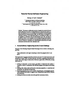
Fig. 1
Architecture principle of a real time computerized system
vice of an installation of a high safety level (SIL4 for instance) involving “a” functional incorrectness that persists in the final code will lead to an accident after a certain time, in a deterministic way. Experience shows us that this scenario exists ; • The architecture support (hardware and software) that has to allow the realization of the system functionalities within a tolerable safety level (i.e. tolerable hazard risk fixed by safety norms). In that case the main question is the following: What level of maximum residual error can be guaranteed by the architecture under real usage conditions? This concerns an unsafe failure rate per hour involving the possibility of an execution error of the system by including active modules and their real-time constraints, the data and control flow… Concerning the first aspect, we have to consider that the “quality development” approach (cf. DO178B or EN50129, 128) cannot alone guarantee that the functionalities of the system are “correct”. This point of view is confirmed by many experiences in Europe [1]. This is the reason why formal methods were introduced to optimize the life cycle cost of computerized critical railway systems. Their advantage is to propose an exhaustive analysis of all possible behaviours of the programmed system and to assure the consistency between the proved behaviour of the model and the behaviour of the code embedded into the system. In this paper, a special focus is brought on the original method developed and used by SNCF for reducing delays and costs with, at least, the same safety level in the development and the validation of new interlocking systems. Our ultimate aim is to define a generic framework supporting a formal proof of SIL4 software. In the scope of this paper, we present the French interlocking system using a functional Petri nets specification. The formal validation method is based on these Petri nets.
2. Railway Safety Context
2.1 The Railway System – A Global Viewpoint
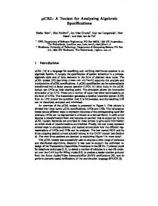
The issue presented in this article is particularly adapted for a railway environment. As we will see later, the biggest difficulty is the writing of exhaustive safety properties, functionality properties and their postulates of validity. In order to make easier the comprehension of the following article, we will give some information about the railway system in general and the French railways in particular. A system is a complex set of interconnected elements aiming to fulfil a function in a given environment. As any industrial process, a system includes three elements: operators-procedures-tools. The railway system consists of operators on the ground and aboard the train who act on an infrastructure and railway equipments in accordance with a procedure. This system can be simplified as shown in Fig. 2. The railway system consists of 4 sub-systems implicating 4 types of operators. Consistent procedures guarantee the perfect understanding of dialogues and the coherence of actions. They constitute the central point of the system safety. They are the result at the same time of an analysis, of technical compromises and of experience collected in 150 years of functioning. This relates to our generic interlocking functions, arranged in layers, to signalling study methods and to SNCF testing procedures which together provide a very high level of reliability. The separation between infrastructure manager and railway undertaking can therefore only be considered under control of experts who will have acquired a high level of functional experience. It is wrong to think that procedures are applied only outside automation; the reality is more complex as: • the operator behaviour is always present to one degree or at another, • moving borders between the operator behaviour and
− 100 −
IJR International Journal of Railway
Formal Validation Method and Tools for French Computerized Railway Interlocking Systems
Fig. 2
Position of the interlocking installation in the railway system
tools can collide, beyond a certain threshold, with problems of a considerable complexity, • maintaining a good equilibrium is a permanent objective of research. The technical characteristics of the railway seem to lead to an unstable system. In fact, they also allow us to identify and to easily anticipate potential conflicts and they impose to put safety in the centre of the actions of all operators. On the whole, the combination of all these points has allowed constructing a very safe system based on simple and robust infrastructure installations. 2.3 Identification of dangerous events
5 types of configuration and 7 types of dangerous events result from the application of these rules and the analysis of the different possible “intersection” of one-dimensional sections. They are : 1o collision * 1o head-on collision * Two running move towards each other1 o 2 convergence 2o counter collision * Two running move toward to the same track [1] or Two running use crossing routes 4o divergence * 3o opening * Switch movement under the train [2] 5o succession * 4o overtaking * Two running with the same direction that approach each other2 5o runaway * Running without breaking 6o derailment For example : Flaugeac derailment in France in 1985 : 40 deaths For example : Gagny derailment in France in 1933 : 200 deaths
Running that looses the guidance of the rail 7° collision Running that collides with an obstruction3 2.4 Interlocking Functions
For all configurations and dangerous events marked by an asterisk (*) “interlocking functions” were worked out and were validated in situ, based on experience. Their principles are written in a quasi formal way4 so that it is easy to establish the “test sheet” for every (new or modified) interlocking system. This specification sheet incorporates intrinsically the safety properties, the properties representing the expected functioning and the postulates of working. We have to notice that with failsafe relay technology, all these functionalities are tested with a cover rate of 100% before putting the system into service. Before allowing the passage of a train in a zone that includes turnouts, it is necessary to be sure that: 1. the route is free (trains in sense of permissive block, operators…), 2. switches are properly moved and locked, 3. the route is protected against trains converging, cutting, or running in the opposite direction, 4. these conditions will not be changed before the train exits the route. It is not possible, in complex zones used by several routes, to assign these tasks to a movement operator with only the assistance of procedures at his disposal. Therefore we utilise mechanical and/or electrical devices called interlockings that forbid the movement of signals and
1
3
2
4
Vol. 2, No. 3 / September 2009
For example : level crossing obstruct by a stopped car or truck In the general way with a « fail safe relay language
− 101 −
Marc Antoni
switches in conditions incompatible with the traffic safety. These devices can be classified in two categories: • interlocking for the passage of trains (continuance of the turnout in the safe position), • interlocking between turnouts in order to assure that all turnouts rest in a safe position. • the imperative switch control assures that the turnouts are in a safe position, fixed and locked and acts on signals. • the approach interlocking forbids the modification of the route during the occupation of the approach zone by the trains by fixing the admission signal in the open position. The closing of the signal in front of the train would liberate the transit interlocking (see below), • the transit interlocking fixes all turnouts before and during the passage of the train. It is active until the train releases the conflict zone (in flexible transit) or up to the clearing of the entire route (rigid transit). It employs an orientated chaining (according to the movement direction) of the zones composing the route. It is deployed from the construction of the train-path on, • the sense interlocking forbids the simultaneous opening of the signals of two routes of opposite sense The line of a route implements some of these interlocking functions which act successively and are raised according to clearing by the circulation. In modern interlocking systems, interlocking functions are now accomplished by logical equations or Petri nets interpreted on high integrity safety computers. In all cases if a system failure (sensors, computer…) occurs, the signaller will have to execute some procedures to assure the trains circulation.
2.5 French Interlocking System
On a PI5 system tasks related to the functional safety properties are performed by the computerized interlocking module called MI6. Its architecture is designed in three levels, allowing a minimization of the life cycle cost and guaranteeing a good interoperability between the functional Petri nets and the target machine. The three levels are: a hardware not specific to the railway domain: industrial conditioned personal computer, industrial power supply, and industrial input-output interfaces are used, a software independent from both hardware and funcPI = Poste Informatique : French computerized interlocking MI = computerized interlocking module: the hardware and the low software (resources manager, interpreter and safety mechanisms) are the same for all modules - each one used its own Petri nets file, which defines all the functionalities.
5 6
tional properties which manages resources (input, output, and internal memory) and interprets the functional Petri nets using a panel of imposed rules. It has been developed in compliance with SIL4 EN 50129,128 standards, and its design is identical on operating French interlocking systems since 1995, functional Petri nets based on “generic bounded Petri nets” parameterized for each track description: the number of accessible states of the system is thus limited. In the following, the term “interpreter” will be used to refer to the second level software, which interprets the “functional Petri nets”. The functional Petri nets are state graphs described by formal semantic rules and saved in an ASCII file. They are interpreted in real time by the “interpreter” of the target machine. The formal semantic rules result in: a deterministic behaviour of the interpreter, a non-ambiguous comprehension (writing, reading, modifying…) of the functional Petri nets by railway engineers and railway maintainers. The MI was designed in order to integrate constraints necessary for the validity of the method and the tools. The MI module integrates the fundamental properties that allow for the application of our proposed method, i.e.: the chronology of all external events is recorded, whatever their duration is, only one event at a time is processed, the graphs (functional Petri nets) are directly interpreted, without being rewritten, the interpretation rules are defined once. Because of these specific properties and the conception properties, the MI module is a pure deterministic machine. The first two levels fulfil tasks with a very high safety level (SIL4), thus, it is not necessary to consider these elements during the check. The MI architecture gives satisfaction so that the next interlocking system of the French railway network will use the same principle and properties.
3. Formal Validation Method of the French Interlocking 3.1 Problem Definition
The aims of a formal validation of the functionalities of French interlocking systems are: the reduction of the life cycle costs of interlocking systems (development, functional evolution and replacement of the target system…) : a real interest for railway infrastructure maintenance engineering , to maintain the direct safety level of non-computerized interlocking system against the background of the increasing functional complexity and the current
− 102 −
IJR International Journal of Railway
Formal Validation Method and Tools for French Computerized Railway Interlocking Systems
limits of qualification processes : safety based on the quality of the development level, on test scripts with limited cover rate…, to maintain the reliability of our non-computerized interlocking against the background of technology changes, of the increasing functional complexity and of specification of the new computerized systems…, the equipment of SNCF with an operating method for formal validation used by the railway test engineers without the help of persons highly educated in mathematics [3]. This method helps them and increases their efficiency by using tools that implement the boring part of the testing process, the promotion of formalization in order to preserve the railway safety knowledge. Our proposed method relies on a mathematical formal proof of the specifications described by functional Petri nets and interpreted in real time by the French interlocking system. We do not execute test scripts but we completely verify that the system does follow the safety properties and the expected functional properties at any time and does not show superfluous conditions. To reach this goal, we use, on the one hand, the properties of Petri nets and, on the other hand, the fact that our interlocking target machine is strictly deterministic and based on a realtime interpretation of the functional Petri nets. For these reasons, the number of system states is finite. The difficulty of our study was to find a solution for potential blocking situations during a practical implementation of the formal method on a real interlocking system, especially concerning: the control of the number of states that can be reached by the system and that have to be checked, the capacity to express the safety rules to be
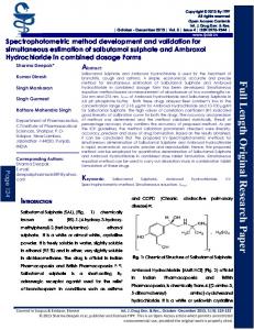
Fig. 3
Vol. 2, No. 3 / September 2009
checked (safety properties and superfluous conditions), the realization of algorithms and tools allowing to accomplish the proof…
3.2 Principles of the Formal Validation Method
In a general way, a target machine of interlocking system (functions and parameters) has to accomplish all necessary functions to guarantee the rail traffic safety: no accident. An error of specification, comprehension or of design will provoke a non reliable functioning and an accident, sooner or later (these systems work twenty-fourseven for several dozens of years) [1]. It will provoke a brutal transition by functional error to a malfunction system state. The formal validation has to guarantee that the interlocking system will always be sure for all functionally reachable system states, in nominal or in degraded modes. Our method is a formal validation method of safety properties (direct and indirect through procedures and operations) derived from educational research studies [4]. Used with the PI, it covers all fields from the specification up to the execution (SNCF approval for being suitable for work). In comparison to other validation and proof of the conformity methods (model-checking, languages B, SDL....) our method has the following specific characteristics: The method is not based on the “modelling” of the expected functionality (with an unknown offset between the models and the real execution context, the gap between the modelling of the application code execution and the real time execution) but it works directly on the executable specifications implemented (after a simple file copy) in the target machine. It cov-
Principle of the formal proof − 103 −
Marc Antoni
ers all steps from specification up to realization. Its application is possible without the requirement for understanding complex mathematics. The writing of the safety properties is straightforward; it can be done for example by SNCF railway engineers. It is automated and the application does not require manual interventions. The principles of the method are particularly simple. The fundamental idea is: “If a property is true in an occupied (marked) state and if the conservation of this property during the transition that follows this state is ensured the property will be true in the new occupied state. The demonstration can be continued as long as the property is preserved”. This principle is used for safety properties and functional properties. The industrial application of the method required the development of appropriated tools: to define the safety (and functional) properties, to define the manner of evaluating the conservation of the safety (and functional) properties for each transition between system states, to define an initial state before the proof application; in this initial state the safety properties are true, to evaluate the safety properties by recurrence for each transition between system states; the safety properties are evaluated until all safety properties are true; otherwise the proof is stopped. We directed our work into the following directions: reduction of the combinative explosion (control of the number of states reached by the system), identification and formalization of the safety properties, methods for the exploration of accessible system states before the proof, development of a tool to carry out the proof, development of upstream and downstream tools to apply the proof in an industrial way, application of the method on a small but real functional interlocking system, inclusion of our method in the current validation process.
3.3 Developed Tools for our Formal Validation Method Tools A: general way for the definition of safety properties
The safety properties are written in an unambiguous and real-time exploitable way by the proving tool. For each signalling function we use Petri nets to write down the associated safety properties. We carry out this work together with railway engineers. All safety properties are grouped together in a special database, which has to be completed for every existing signalling function (Fig. 9). The evaluation of the safety properties generates one of three possible results: Safety property violation ⇒ stop the proof - give the
sequence of external events that presents an unsure system state; Function property violation ⇒ the system state reached is out of the boundary, the system state is proved but it will not be reintroduced - give the sequence of external events that presents an unexpected system state; Superfluous property violation ⇒ the system prohibits a transition allowed by the safety properties.
Tools B: generation of the safety properties file
The railway employee in charge of the interlocking validation has at his disposal the complete description of the tracks and the signalling system via a specific graphical interface. All the information is combined in a local base (technical report which describes the signalling functions, the interlocking etc.) and used to automatically build the graphical check-board. The safety properties are automatically generated using the local data from the previous database. Thus, they are written, for each proof, in a safety properties file. A consistency check is made between the safety property file and the functional Petri net file.
Tools C: Proving tool: Formal validation tool
The proving tool interprets the functional Petri nets exactly like the final interlocking module. It respects all the rules mentioned earlier. The explorer identifies the totality of system states departing from a safe initial state. The proving tool uses the explorer: to take into account the task limitations of the interlocking system; to evaluate step by step (state by state during the exploration) the safety properties. The combinative reduction is based on a proportion of the routes to be checked, on a limitation of the functions and a specific description of the environment (railway culture). We have developed two algorithms (vertical or horizontal scanning) performing this operation and we compare both results. The proving tool evaluates the safety properties step by step during the automatic and complete exploration (after each system transition). Thus, the transitions between system states are automatically proved. The method stops when a safety property violation is detected. The exploration breaks off and no new system state can be reached.
Tools D: Reached system state tree and execution certificate At the end of the exploration and of the check, a certificate (report) is produced which gives information: about unsure states;
− 104 −
IJR International Journal of Railway
Formal Validation Method and Tools for French Computerized Railway Interlocking Systems
about the sequence of external events that presents an unsure system state. A tool was developed to simplify the data processing in the case of unsure system states. It provides the railway engineer in charge of the validation of the interlocking system with: a tree containing all system state transitions found during the exploration; a precise description of each system state reached; an evaluation of each safety property and the superfluous condition for each system state reached. The tool generates the tracing of the occupied states and the used transitions of the functional Petri nets. The results are saved after the end of the check and are given to the railway engineers in order to help them to detect the reason behind a problem (specification mistake or lack of specification, safety property mistake, badly defined operating rules etc.). The railway engineer has to certify that there are no superfluous conditions or any safety property violations. He also has to identify the shortest way to reach the unsure system state. This tool allows the railway engineer also to check every intermediate data for each system state reached.
3.4 Applications to Real Interlocking - PI of Nurieux
We applied our method to the real interlocking system of “Noisy le Roy” that is currently in use and situated next to Paris. The results were obtained under reasonable delays, directly proportional to the number of tested train routes. For each route checked, we found about 1,500 different system states and around 1 hour calculation time on a normal laptop. We chose some potentially dangerous situations from the experience of railway engineers and we were able to verify that the tools detect them easily. - Double track level crossing
We applied our method to a future level crossing system developed as a little PI. The level crossing was designed for a double track with bi-directional operation on each track, with the possibility to manually control the running of the level crossing in case of sensor failure (e.g. detectors, track circuits). The results were obtained in less than one hour for all the proofs. - New applications
We will apply our method and tools to an interlocking system that has to be put into service before the end of 2008. In collaboration with TUBS7, we will try to link the TUBS = Technische Universitat Braunschweig (Technical University of Braunschweig - Institute for Traffic Safety and Automation Engineering, Germany)
7
Vol. 2, No. 3 / September 2009
university and the railway worlds and to apply the method of German level crossing or interlocking system. Feedback
For us this method is industrially available. At the end of 2008, it will be fully available for use by signal engineers. The automatic and systematic exploration allows checking event sequences that the testers would not normally test due to economic constraints, limited test time or not practically testable scenarios (occurrence of several events during a small reaction delay is present…). The main difficulty in these news studies was to write and obtain expert validation of all the safety properties and the functional properties. Our method needs a rigorous formalization of the functionality of an industrial application based on Petri nets. This generates benefits like: a readable application, fast and simplified maintenance, an easy comprehension for railway engineers and maintainers. 4. Conclusion
Safety and real-time computerized applications are becoming more and more complex, so that the limits of the classical validation methods are now challenged. Formal methods can validate this kind of systems and are a means for finding the best compromise between costs and safety level. Our method is applicable practically and will permit to answer future tasks: the large renewing plan of interlocking systems, the demography of testers and their training. Our proover tool formally verifies that the application code, i.e. the functional Petri nets, meets all applicable safety requirements and all functional requirements. Our methods use the knowledge of the real-time software, and it uses the properties of the SIL4 “interpreter”. The tool applies automated mathematical proof on the functional Petri nets. There is no need to write a single test. If there is an unsafe scenario violating a requirement, the proving tool will find it, generate the corresponding test, and display it in the tool. The engineer then identifies and fixes the unsafe logic and re-runs the tool. This approach is fundamentally different from testing, simulation and review. With the introduction of our proving tool, we no longer have to limit ourselves to check a few scenarios. Our proving tool checks if the final application code is safe for all scenarios. Although, new to some, formal verification will be shortly mature and the proven verification approach used extensively within computerized railway signalling. Our method could be used for the validation of functional specifications (e.g. interlocking system or other
− 105 −
Marc Antoni
automation equipment) before call for tending. By this way, it could be possible to prove that the specifications fulfil all the requirements and that the product is correctly designed. I hope have answered the question of, how can in the computerized future we can maintain the safety level of actual failsafe relay interlockings and, in the same time, decrease the costs of engineering? The method shown in this paper could be used in a common way for all railway engineers to formalize new specifications or functional modifications for interlocking systems. Compared to the current method, this could have the following benefits: The elaboration of safety properties and functional properties will be made by railway engineers and not by mathematicians who do not necessarily have an in depth knowledge of signalling systems, The possibility for each railway network to modify its signalling principles and safety properties in the best economic conditions,
− 106 −
The possibility for manufacturers, if they wish, to interpret directly the functional Petri nets with their own interlocking machine, reducing thus their own validation effort.
1. “ETCS software error led to derailment”, Railway Gazette International (January 2008). 2. “British track faces scruting after 152 km/h derailment”, IRJ (April 2007). 3. M. Antoni, N. Ammad, “Feasibility study for the implementation of a formal proof of interpretable specification (for an interlocking system)”, FORMS/FORMAT 2007 - Proceedings of Formal Methods for Automation and Safety in Railway and Automotive Systems (G. Tarnai and E. Schnieder Eds.), Braunschweig (2007). 4. P. Bielinski, “Implantation VLSI d’un algorithme de code correcteur d’erreur et validation formelle de la réalisation”, Thesis, Université Paris 6 (1993).
IJR International Journal of Railway