languages (DSML) is carefully (and formally) defined, evolved as needed and verified for essential properties (such as well- formedness and consistency) using ...
Proceedings of the ASME 2012 International Design Engineering Technical Conferences & Computers and Information in Engineering Conference IDETC/CIE 2012 August 12-15, 2012, Chicago, IL,
DETC2012-70534 FOUNDATION FOR MODEL INTEGRATION: SEMANTIC BACKPLANE Gabor Simko ISIS-Vanderbilt University Nashville, TN USA Ethan Jackson Microsoft Research Bellevue, WA USA
Tihamer Levendovszky ISIS-Vanderbilt University Nashville, TN USA
Ted Bapty ISIS-Vanderbilt University Nashville, TN USA
ABSTRACT One of the primary goals of the Adaptive Vehicle Make (AVM) program of DARPA is the construction of a modelbased design flow and tool chain, META, that will provide significant productivity increase in the development of complex cyber-physical systems. In model-based design, modeling languages and their underlying semantics play fundamental role in achieving compositionality. A significant challenge in the META design flow is the heterogeneity of the design space. This challenge is compounded by the need for rapidly evolving the design flow and the suite of modeling languages supporting it. Heterogeneity of models and modeling languages is addressed by the development of a model integration language – CyPhy – supporting constructs needed for modeling the interactions among different modeling domains. CyPhy targets simplicity: only those abstractions are imported from the individual modeling domains to CyPhy that are required for expressing relationships across sub-domains. This “semantic interface” between CyPhy and the modeling domains is formally defined, evolved as needed and verified for essential properties (such as well-formedness and invariance). Due to the need for rapid evolvability, defining semantics for CyPhy is not a “one-shot” activity; updates, revisions and extensions are ongoing and their correctness has significant implications on the overall consistency of the META tool chain. The focus of this paper is the methods and tools used for this purpose: the META Semantic Backplane. The Semantic Backplane is based on a mathematical framework provided by term algebra and logics, incorporates a tool suite for specifying, validating and using formal structural and behavioral semantics of modeling languages, and includes a library of metamodels and specifications of model transformations. INTRODUCTION The META design flow is implemented as a model composition/synthesis process that incrementally shapes and refines the design space using formal models that can be
Sandeep Neema ISIS-Vanderbilt University Nashville, TN USA
Joseph Porter ISIS-Vanderbilt University Nashville, TN USA
Janos Sztipanovits ISIS-Vanderbilt University Nashville, TN USA
manipulated. The model composition and refinement process is intertwined with testing, analysis, and verification steps to validate and verify requirements and to guide the design process toward the least complex, therefore the least risky and least expensive solutions. One of the crucial preconditions of achieving DARPA’s Adaptive Vehicle Make (AVM) [1] goal of compressing five-fold the development timeline is the availability of a quality-controlled model library for system components, system contexts, and manufacturing models. The model library includes the basic, reusable building blocks defining a multi-dimensional design space. It serves as a foundation for compositional design strategies where system level properties are computed from properties of components. The success of the META approach depends on a sufficient body of composable, multi-domain, and accurate model repository as well as composition and analysis technology that enable: • Categorization/Taxonomy: Searching for components within a component database. • Modular Design: Insertion into existing and new designs (common/mappable interfaces). • Analysis: Both as a component, and as an assembly of components, supporting all relevant physical/control properties to determine how the actual component will work. Analysis will span from simple properties, through dynamics, to detailed first order analysis. • Build/Assemble: data necessary to construct and/or assemble the actual component into a system. In META, as well as in all other approaches to modelbased design, modeling languages and their underlying semantics play fundamental role in achieving compositionality. The tremendous heterogeneity of the AVM design space, and the need for rapidly evolving/updating the design flow requires a rich set of modeling languages usually determined by existing and emerging model-based design, verification and simulation
1
Copyright © 2012 by ASME
technologies and tools. Consequently, the META language suite and the related infrastructure cannot be assumed to be static; it will continuously evolve. To address both heterogeneity and evolvability simultaneously, we departed from the most frequently used approach to address heterogeneity: the development or adoption of a very broad and necessarily hugely complex language standard covering all aspects of the AVM domain (and more). Instead, we place emphasis on the development of a model integration language – CyPhy – with constructs limited to modeling the interactions among different modeling aspects. CyPhy targets multi-modeling – it advances multi-modeling from a mere “ensemble” of models to a formally and precisely integrated, mathematically sound suite of models. Integration of the modeling language suite by CyPhy is minimal in a sense that only those abstractions are imported from the individual languages to CyPhy that are required for expressing coupling across sub-domains. This “semantic interface” between CyPhy and the domain specific modeling languages (DSML) is carefully (and formally) defined, evolved as needed and verified for essential properties (such as wellformedness and consistency) using the methods and tools of formal metamodeling. By design, CyPhy is moving in the opposite direction to unified system design languages, such as SySML [28] or AADL [29]. Its goal is specificity as opposed to generality and heavy weight standardization is replaced by layered language architecture and specification of explicit semantics. The goal of this paper is to describe thes key components of the META Semantic Backplane, our language engineering infrastructure. Details of CyPhy and the structure of the overall META tool chain are presented elsewhere. We start by discussing characteristics of the AVM design flow and AVM components from model integration point of view. We follow this by providing an overview of the Semantic Backplane. The paper will provide details on the selected method of formal modeling of the semantics of modeling languages and presents examples for specifications. The central message of this paper is that formal semantic foundations for designing and composing DSMLs are sufficiently mature to support an agile approach to design automation, one that can be tailored to actual needs without sacrificing soundness. AVM DESIGN FLOW IMPACT ON THE META MODEL INTEGRATION LANGUAGE The META design flow proceeds in the following main phases: 1. Combinatorial Design Space Exploration using static finite domain constraints and architecture evaluation. 2. Behavioral Design Space Exploration by progressively deepening from qualitative discrete behaviors to precisely formulated relational abstractions and to quantitative multiphysics, lumped parameter hybrid dynamic models using both deterministic and probabilistic approaches.
3.
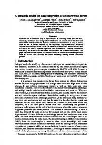
Geometric/Structural Design Space Exploration coupled with physics-based nonlinear PDE analysis of thermal, mechanical and mobility properties. 4. Cyber Design Space Exploration (both HW and SW) tightly coupled to continuous system dynamics. The design space exploration phases are linked to probabilistic and deterministic verification methods and are guided by complexity metrics. The META design flow introduces heterogeneity in multiple dimensions: 1. Heterogeneity caused by multiple physics domains (structural, mechanical, electrical, hydraulic, pneumatic and others). 2. Abstraction heterogeneity across implementation layers (continuous/hybrid dynamics, logical time dynamics (automata models), discrete event dynamics). 3. Heterogeneity across behavioral abstractions developed for describing the same dynamic phenomenon (e.g. hybrid dynamics abstracted to concurrent state machines using precise relational abstractions). The modeling domains across these design dimensions are not closed: they continuously evolve; new modeling and analysis methods are developed and need to be incorporated in the design flow. In order to achieve the required flexibility in the META language design without sacrificing precision, we developed the CyPhy Model Integration Language. The approach followed in CyPhy is demonstrated in Figure 1.
Figure 1. Model integration language concept
The domain-specific modeling languages addressing various aspects of the heterogeneous design space are introduced by a variety of tools (such as Simulink [23], Modelica [24], TrueTime [25], Pro/ENGINEER [26], ThermalDesktop [27], etc.) with their own syntax and semantics. Many of these languages are complex, not necessarily because of the innate domain complexity, but auxiliary complexities caused by an insatiable push for generality or various incidental tool functions. The CyPhy
2
Copyright © 2012 by ASME
approach filters these complexities out and abstracts in the CyPhy integration domain only those concepts that are essential for cross-domain integration. This approach enables keeping CyPhy semantics simple, but sufficient for creating meaningful cross-domain integration models. The languages are represented in the CyPhy domain via their semantic interface defined by metamodels. These metamodels are specified using the META Semantic Backplane tools. The bridge between CyPhy and the integrated domain specific tools’ modeling space is created by semantic translators. The semantic translators extract and transform the domain specific models into the CyPhy model integration space according to their semantic interface. The same technique is used to integrate with CyPhy highly complex, heavyweight modeling languages, such as SySML, AADL or others.
Model Integrated Computing (MIC) metaprogrammable tool suite [30]. In the Meta-Level Tool Architecture (see Figure 3), domain-specific modeling, modeling languages and tool chains (top layer) are specified and integrated using the Meta-Level methods and tools (middle layer). The Meta-Level includes metamodels of component DSMLs, and metaprogrammable tools for modeling (Generic Modeling Environment – GME), model data management (Unified Data Model tool – UDM), model transformation (Graph Rewriting and Transformation tool - GReAT), and tool integration (Open Tool Integration Framework – OTIF). These tools are part of Vanderbilt’s open source Model- Integrated Computing tool suite [12] that have been developed over two decades and have been matured in a wide range of applications from process engineering to automotive, manufacturing to defense.
AVM COMPONENT IMPACT ON THE META MODEL INTEGRATION LANGUAGE META Components span a broad range as can be seen in Figure 2. Components are modeled using a variety of domain tools with their own domain specific notations, for example, component physical dynamics may often be modeled in Simulink or Modelica, while software models may range from AADL models to UML class diagrams and to Simulink Stateflow models.
Figure 3. Meta-level tool architecture
The META Semantic Backplane constitutes a “language engineering environment”, where DSMLs and tool chains can be rapidly designed and evolved. The Meta Level (mid-layer) is built on the Semantic Level (lower layer) that includes the theories, methods and tools required for making the overall Meta-Level architecture sound. Figure 2. Heterogeneous components in AVM
Our CyPhy integration language approach can handle this diversity by not attempting to integrate all information within the integration model itself, rather keeping the model artifacts in their native format, but maintaining links to the relevant information encoded within the CyPhy model. By linking the component models with the CyPhy integration models the detailed models can be recalled for deep analysis, while the information in CyPhy about the component is used in the composition and execution of the analysis.
Figure 4. Components of the META semantic backplane
SEMANTIC BACKPLANE Our modeling language and tool integration strategy has been built on Vanderbilt’s Meta-Level Tool Architecture and the
The structure of the META Semantic Backplane is shown in Figure 4. The META design flow is manifested on the Semantic Backplane as a suite of formal specifications:
3
Copyright © 2012 by ASME
specification of DSMLs using metamodels and specification of model transformations as mappings among metamodels. The primary functionalities of the META Semantic Backplane are Metamodeling, Metamodel Analysis and Verification and Metageneration. These functionalities are supported by Languages, Models and Tools as shown in Figure 4. 1.
2.
3.
Tools: The Semantic Backplane includes the MIC tool suite: (a) GME configured for building metamodels using the metamodeling language MetaGME [10][11], (b) the GReAT model transformation tool suite for specifying model transformations using the transformation specification language (UMTL) and compiling the specifications into executable Model Transformation Tools [17], (c) the Unified Data Model (UDM) tool suite for specifying and generating model management backends and (d) the Open Tool Integration Framework [12]. A recently completed component of the Semantic Backplane tool suite is the translator toward FORMULA [4], a tool that can be used for formally verifying and validating metamodels and specifications of model transformations. FORMULA [3] is the result of the continuation of research at Microsoft Research started at Vanderbilt on structural semantics. There is ongoing collaboration between Vanderbilt and MSR in developing and using FORMULA in various foundational aspects of model-based design, particularly as a formalism for describing formal semantics of modeling languages. Languages: The Semantic Backplane includes language for metamodeling – MetaGME – and language for specifying model transformations – GReAT. The languages are functionally complete: metamodels specified in MetaGME are used for configuring metaprogrammable tools and can be translated into alternative metamodeling languages (used in the Eclipse Modeling Framework, the UML tool suites or MOF). Model transformations specified in GReAT can be compiled into fast Model Transformation Tools. For metamodel analysis and verification we use FORMULA. The Meta-Level tools include a translator that translates metamodels (and GReAT model transformations in the future) into FORMULA. Models: Modeling languages and model transformations deployed in the META tool chain are specified by MetaGME metamodels and GReAT. If formal verification of metamodels and model transformations is required, the metamodels are translated into FORMULA and their semantics is refined. The metamodels, transformation models and FORMULA specifications provide the core semantic foundations that keep the modeling languages used in the evolving META tool chain and design flow sound.
It is important to note that the use cases for tools, languages and models in the Semantic Backplane are fundamentally different from that of the engineering tools in the META design
flow. Meta Level modeling, and model verification activities are highly focused and used only when the META design flow and tool suite is changing (e.g. new modeling languages and analysis methods are adopted). It needs to be done by a small team responsible for the overall integrity of the tool suite. Specifying DSML semantics is an essential task for meaningful integration and exchange of models. Without semantics, models become loose artifacts open to misinterpretation. This problem compounds as models are integrated and exchanged. However, providing a framework for specifying and composing semantics is challenging for several reasons: (1) Unlike traditional programming languages that share the Turing machine as a common foundation, DSMLs vary in the nature of their semantics. (2) Direct specification of semantics as mathematical formulas, e.g. by logic, sequent calculi, or trace algebras, requires expertise as a mathematician and language designer. (3) Manual composition of DSMLs semantics by manipulation and (semi-automated) correctness proofs is not practical. In general, models represent a structure (e.g. a mechanical assembly) and associated behaviors. Accordingly, specification of modeling languages requires support for specifying both structural and behavioral semantics. We have developed a process, called semantic anchoring that allows the precise mapping of highly domain specific notations to mathematically sound semantic domains. Given the lack of space, we show only a short summary of these results with the purpose of showing their role and use in the proposed project. STRUCTURAL SEMANTICS Structural semantics defines the set of well-formed models that can be created in a DSML. The set of well-formed models can be defined by a type language and a constraint language. MetaGME uses UML class diagrams as type language and the Object Constraint Language (OCL). We have completed the formalization of structural semantics using the mathematical framework of Constraint Logic Programming (CLP). The degree to which we can reason about metamodels depends on the expressiveness of the constraint logic. Some examples we used for checking expressiveness are: (1) Models of component-to-CPU deployments where legal models must be schedulable. (2) Models of dataflow systems where legal models never deadlock and always use bounded memory. (3) Models of system state where legal models are those states satisfying invariants[14][15]. Prior work at Vanderbilt led to the first version of FORMULA (Formal Modeling Using Logic Programming and Analysis) that used non-recursive Horn logic, for deciding well-formedness or malformedness of model instances. Lately, this work has been extended at Microsoft Research to an extended Horn logic with stratified negation [3][16]. The current version of FORMULA combines two wellstudied branches of mathematics: algebraic data types (ADTs) and first-order logic with fixpoints (FPL). The latter is parameterized by background theories including Presburger
4
Copyright © 2012 by ASME
arithmetic, bit vectors, term algebras, lists, arrays, and sets. It employs ADTs for describing the basic structure of models, which may include architectural diagrams, abstract states, data sets, or lines of code. The semantics of these structures is specified by constraint logic programming (CLP), yielding a
FORMULA provides a first-class module system for composing specifications with formal guarantees. The key formal method provided by FORMULA is a world search procedure: Does there exist an extension of a logic
Table 1. Model elements of acausal bond graphs 1 domain AcausalBG_elements 2 { 3 primitive Sf ::= (id: String). 4 primitive Se ::= (id: String). 5 primitive R ::= (id: String). 6 primitive C ::= (id: String). 7 primitive I ::= (id: String). 8 primitive TF ::= (id: String). 9 primitive GY ::= (id: String). 10 primitive ZeroJunction ::= (id: String). 11 primitive OneJunction ::= (id: String). 12 Source ::= Sf + Se. 13 Storage ::= C + I. 14 OnePort ::= Source + R + Storage. 15 TwoPort ::= TF + GY. 16 BGElement ::= OnePort + TwoPort. 17 Junction ::= ZeroJunction + OneJunction. 18 BGNode ::= BGElement + Junction. 19 primitive Bond ::= (id: String). 20 [Closed] primitive Src ::= (Bond,BGNode). 21 [Closed] primitive Dst ::= (Bond,BGNode). 22 }
Table 2. Excerpt from the structural semantics of acausal bond graphs 23 domain AcausalBG extends AcausalBG_elements 24 { 25 invalidBondDef := a is Bond, no Src(a,_). 26 invalidBondDef := a is Bond, no Dst(a,_). 27 … 28 bondConn(a,x) :- Src(a,x); Dst(a,x). 29 atLeastOneConnection(x) :- bondConn(_,x). 30 atLeastTwoConnections(x) :31 bondConn(a,x), bondConn(b,x), a != b. 32 exactlyOneConnection(x) :33 atLeastOneConnection(x), 34 no atLeastTwoConnections(x). 35 … 36 invalidBlock := x is OnePort, 37 no exactlyOneConnection(x). 38 invalidBlock := x is TwoPort, 39 no exactlyTwoConnections(x). 40 invalidBlock := x is R, Src(_,x); 41 x is C, Src(_,x); 42 x is I, Src(_,x). 43 invalidBlock := x is TwoPort, no Src(_,x); 44 x is TwoPort, no Dst(_,x). 45 … 46 conforms := !invalidBlock & 47 !invalidBondDef & 48 !invalidSrcDef & 49 !invalidDstDef. 50 }
declarative and programmatic means for assigning meaning to structures via FPL. This style can be used to attach rich constraints to the ADTs for structural semantics, or to describe the evolution of structures for behavioral semantics.
program (a world) where a goal is satisfied? This single procedure supports many analysis scenarios, including: (1) Consistency checking – Does there exist a legal model?, (2) Synthesis – Does there exist a model that has a certain property?, (3) Design space exploration – Do there exist many models that have a property?, (4) Model checking – Does there exists an initial model and sequence of steps where a property holds over the steps. World search is solved by two state-of-theart techniques: Symbolic execution converts a search problem into a symbolic constraint satisfaction problem, generating as few constraints as possible. A state-of-the-art satisfiability modulo theories (SMT) solver is applied to efficiently solve the constraint problem [16]. EXAMPLE FOR DEFINING STRUCTURAL SEMANTICS Figure 1.
MetaGME metamodel for the simplified bond graph language
Figure 5: Bond graph metamodel in metaGME
We now illustrate these ideas by defining structural semantics for a simplified bond graph modeling language (Figure 5 and Table 1-2). Bond graphs are graphical representations of physical dynamics. The arcs in a bond graph
5
Copyright © 2012 by ASME
represent bi-directional energy flows and span multiple physical domains [22]. Due to their generality, we chose bond graphs as one of the formalism for systems dynamics in META. In the specification below we separated the domain of model elements from the domain of well-formed bond graphs, because the separated specification allows easier documentation. However, note that the well-formedness rules are strictly part of the bond graph domain, so Table 1 and Table 2 need to be regarded as two parts of the structural semantics. (The MetaGME metamodel for the simplified bond graph language is shown in Figure 5.) The domain AcausalBG_elements (Line 1 in Table 1) encapsulates the model elements of bond graphs. Simple bond graphs have nine types of blocks and bonds between these blocks [22]. Basic building elements are specified through ADT declarations (lines 3-14, 19-21). Each of these lines represents a data constructor, which can be used to construct model elements, and each object is identified with a unique string ID. The keyword primitive marks constructors that are used as modeling elements. The special Closed annotation in lines 20-21 indicates that constructors Src and Dst only take elements that have been placed directly in the model. Lines 12-18 show type inheritance in bond graphs, where operator + denotes the union of sets (cf. Figure 1). As we have shown in Figure 4, the META Semantic Backplane defines modeling languages in two forms: as metamodels defined in MetaGME [12][20] and formal metamodels defined in FORMULA. The MetaGME metamodels are used by the metaprogrammable tools of the MIC tool suite, such as GME, GReAT and UDM [12]. While precise and captures all well-formedness rules of languages, this formalism is not sufficiently rich for reasoning, and expressing more advanced concepts such as well-formedness rules for evolving structures. The two formalisms are linked, MetaGME metamodels can be translated into FORMULA metamodels. The domain of well-formed acausal bond graph models is a subset of the domain of AcausalBG_elements as defined in Table 2. The subset relation is captured by the extends keyword in Line 23. The well-formedness rules in Table 2 express the valid configurations of the elements, e.g. lines 25-26 state that each bond should have a Src and Dst. Line 28 defines a nonprimitive data constructor bondConn, where semi-colon represents logical or. bondConn(a,x) expresses the fact that bond a is connected to node x. Lines 29-34 count the number of connections of each node. Lines 36-39 state that one-port elements should have exactly one connecting bond, and twoport elements should have exactly two connecting bonds. Lines 40-42 express the rule that resistance and storage elements cannot be the sources of bonds. Finally, two port elements should act in source and destination roles as well (lines 43-44). The keyword conforms (lines 46-49) captures the structurally well-formed models of the domain.
BEHAVIORAL SEMANTICS Behavioral semantics is represented as a mapping of the model into a mathematical domain that is sufficiently rich for capturing essential aspects of the behavior (such as dynamics). In other words, the explicit representation of behavioral semantics of a DSML requires two distinct components: (a) a mathematical domain and a formal language for specifying behaviors, and (b) a formal language for specifying transformation between domains. In our previous work on semantic anchoring [20], we followed operational semantics style of specifications, where behavior is described by a set of rules specifying how the state of an actual or hypothetical computer changes while executing a program [18]. We formalized behavioral semantics based on Abstract State Machines (ASM) [6] and represented model transformations as graph transformation [17] (taking advantage of the GReAT model transformation tool of the MIC tool suite [12]). Based on this approach, we have developed a semantic anchoring tool suite [7] that enables the compositional specification of behavioral semantics - an essential requirement for creating an open DSML-based modeling language framework. However, this method had several drawbacks: 1. The formal framework used for specifying model transformation (graph grammars) and operational semantics (ASM) were different. Consequently, reasoning across these different domains was hard and understanding the specification was somewhat complicated. Since we intend to use the Semantic Backplane for generating reference traces using simulation, proving properties and invariants across domains, a unified formal framework is highly desirable. 2. Heterogeneity of AVM artifacts requires using modeling languages where behavioral semantics is more naturally represented denotationally: by formalizing the meaning of modeling languages via mathematical objects (denotations) which describe the meaning of modeling constructs. A common example in AVM is continuous dynamics, where the natural formalism for expressing semantics is differential algebraic equations (DAE). The challenge here is the specification of the model-to-model translator that maps the modeling language to differential equations. (With this, we can also separate the specification of formal semantics from issues such as full abstraction that examines operational equivalence of simulators with the denotational specification of dynamics.) In recent work we have explored defining behavioral semantics fully in FORMULA and found the results promising. The primary advantage is that structural and behavioral semantics are expressed in the same formal framework greatly decreases specification complexity and allow more extensive verifications.
6
Copyright © 2012 by ASME
EXAMPLE FOR DENOTATIONAL SPECIFICATION OF BEHAVIORAL SEMANTICS The specification of the transformation from bond graph models to DAE-s defines denotational semantics for bond graphs. We show the formalization of this specification using FORMULA. First, we need to specify the target domain, the domain of (a subset of) DAE-s. This domain should be generic enough to allow the representation of DAE-s arising from the translation of bond graphs. Table 3 shows the FORMULA encoding of such a domain. Variable-s are named and indexed elements (lines 3-4), while Parameters are indexed elements (Line 5). In lines 6-8 two unary operators (negation and inversion) and one binary operator (multiplication) are defined. The summation operator in lines 9-10 is an n-ary operator identified by a string ID, and n Addends, which define the terms over which the Sum is interpreted. A term is a variable, a parameter, or an operator (lines 11-12). Finally, three kinds of Equation-s are defined (lines 13-16). Eq defines an equation, where the left-hand side Table 3. Model elements of differential algebraic equations 1 domain DAEquations 2 { 3 primitive Variable ::= 4 (name: String, id: String). 5 primitive Param ::= (id: String). 6 primitive Neg ::= (Term). 7 primitive Inv ::= (Term). 8 primitive Mul ::= (Term, Term). 9 primitive Sum ::= (id: String). 10 primitive Addend ::= (Sum, Term). 11 Term ::= Variable + Param + 12 Neg + Inv + Mul + Sum. 13 primitive Eq ::= (Variable, Term). 14 primitive DiffEq ::= (Variable, Term). 15 primitive SumZero ::= (Sum). 16 Equation ::= Eq + DiffEq + SumZero. 17 }
is a single variable and the right-hand side is an arbitrary term. DiffEq defines a differential equation, where the left-hand side is the time-derivative of a single variable and the right-hand side is an arbitrary term. SumZero makes the specified summation zero. Bond graph denotational semantic mapping is accomplished by specifying the transformation from the domain of acausal bond graphs to the domain of differential algebraic equations. Each bond determines a pair of power variables, the effort and the flow variable. We write ea to denote the effort, and fa to denote the flow of bond a. Bond graph nodes define equations on the corresponding bond variables, usually using some parameter of the node. We write px for the (assumed) parameter
of node x. Table 4 shows the denotational semantic mapping of bond graphs in FORMULA. Lines 1-3 define a transformation from the domain of AcausalBG to the domain of DAEquations. Line 5 equates the effort on a bond connected to a source of effort to the (effort) parameter of the source, where Connects(a,x) is a derived data constructor, and expresses Src(a,x) or Dst(a,x). The denotational meaning of a source of effort is fully enclosed in this single line. Similarly, Line 6 defines the equality on flow variables connected to source of flows. Line 7 gives the semantic meaning of resistance by formulating the connection between the flow and effort variables on the resistance. Lines 8-11 show the differential equations imposed by capacitance and inductance. These are the only rules expressing differential equations in the transformation. Inherently, all the states of the physical system are captured by these equations. Lines 12-17 define the semantics of transformers and gyrators. The meaning of OneJunctions is specified in line 18-24. In detail, lines 18-21 define 1-junctions by applying Table 4. Denotational semantic mapping of bond graphs 1 transform BG_DenotationalSemantics 2 from in1::AcausalBG 3 to out1::DAEquations 4 { 5 Eq(ea,px) :- x is Se, Connects(a,x). 6 Eq(fa,px) :- x is Sf, Connects(a,x). 7 Eq(ea, Mul(px,fa)) :- x is R, Dst(a,x). 8 DiffEq(ea, Mul(Inv(px),fa)) :9 x is C, Dst(a,x). 10 DiffEq(fa, Mul(Inv(px),ea)) :11 x is I, Dst(a,x). 12 Eq(ea, Mul(px,eb)), 13 Eq(fb, Mul(px,fa)) :14 x is TF, Dst(a,x), Src(b,x). 15 Eq(ea, Mul(px,fb)), 16 Eq(eb, Mul(px,fa)) :17 x is GY, Dst(a,x), Src(b,x). 18 Addend(Sum(x.id),ea) :19 x is OneJunction, Dst(a,x). 20 Addend(Sum(x.id),Neg(ea)):21 x is OneJunction, Src(a,x). 22 EqSumZero(Sum(x.id)) :- x is OneJunction. 23 Eq(fa,fb) :- x is OneJunction, 24 bondConn(a,x), bondConn(b,x). 25 Addend(Sum(x.id),fa) :26 x is ZeroJunction, Dst(a,x). 27 Addend(Sum(x.id),Neg(fa)):28 x is ZeroJunction, Src(a,x). 29 EqSumZero(Sum(x.id)) :- x is ZeroJunction. 30 Eq(ea,eb) :- x is ZeroJunction, 31 bondConn(a,x), bondConn(b,x). 32 } Kirchoff’s voltage law on the connected bonds. Lines 22-24
7
Copyright © 2012 by ASME
specify the equality of flows between connected bonds. As an immediate consequence, 1-junctions are clearly defining topological concepts, namely the serial connection of elements. Similarly, lines 25-31 define the meaning of ZeroJunction, which represent parallel connections. EXAMPLE FOR OPERATIONAL SPECIFICATION OF BEHAVIORAL SEMANTICS Similarly to ASM-based specification [21], operational semantics for behaviors is accomplished by modeling the abstract state and the ways this state can evolve. In FORMULA this is accomplished also by ADTs and logic programs. However, instead of using the logic program to compute whether a model is well-formed, or to specify model transformations, the program is used to compute the model’s next state from its current state. We illustrate this by defining structural semantics and operational semantics for deterministic finite state automata defined by the simple language of DFA (Table 5). The domain block encapsulates the structural semantics of the DFA language (Line 1). The majority of the specification is a set of ADT declarations (Lines 2-6). Each of these lines declares a data constructor, which can be used to construct model elements. For example, the State constructor can be used to construct states labeled by integers. The more interesting constraint is that the DFA must be nondeterministic. This is specified in Lines 7-8 by a logic programming rule that searches for two transitions starting at the same state and triggering on the same event, but ending on distinct states. If such transitions exist, then the query nonDeterTrans evaluates to true; false otherwise. Every domain contains a special query called conforms that determines if a model is legal. Line 9 shows the conforms rule for DFAs; it evaluates to true if the nonDeterTrans query evaluate to false, i.e. it does not detect any non-deterministic transitions. Table 5. Structural semantics of a deterministic finite automata modeling language 1 domain DFA { 2 primitive Event ::= (lbl: Integer). 3 primitive State ::= (lbl: Integer). 4 primitive Transition ::= (src: State, 5 trg: Event, dst: State). 6 primitive Current ::= (st: State). 7 nonDeterTrans := Transition(s, e, sp), 8 Transition(s, e, tp), sp != tp. 9 conforms := !nonDeterTrans. 10 } Table 6 shows the FORMULA approach for defining operational semantics using model transformations. Transformations require vectors of parameters and models as inputs, and produce vectors of models as outputs. A parameter
is an external value used by the transformation. For example, the Step transform has one parameter, called fire, requires one input DFA model, called in1 (Line 2), and produces one output DFA model, called out1 (Line 3). Inside a transformation are rules that search over the input modeling elements in order to generate the output modeling elements. After all the output modeling elements are generated, FORMULA collects these elements and emits the resulting model. Table 6. Operational semantics for FDA 1 transform Step 2 from in1::DFA 3 to out1::DFA 4 { 5 out1.State(x) :- in1.State(x). 6 out1.Event(x) :- in1.Event(x). 7 out1.Transition(s, e, sp) :8 in1.Transition(s, e, sp). 9 out1.Current(sp) :- in1.Current(s), 10 in1.Transition(s, fire, sp). 11 out1.Current(s) :- in1.Current(s), 12 fail in1.Transition(s, fire, _). 13 } The Step transformation captures the operational semantics of DFAs by generating a new automaton with an updated current state marking, depending on the current state of the input automaton and the event fire provided by the environment. Lines 5-6 copy the structure of the input automaton to the output, since this does not change. Notice the use of the in1 and out1 prefixes to distinguish between input and output elements. The FORMULA compiler also performs type inference to automatically coerce elements from inputs to outputs. For example, the variable s in Line 7 appears under a in1.Transition(,,) constructor. It must have the type in1.State on the right-hand side of the rule. On the left-hand side it appears under an out1.Transition(,,) constructor, so it must have the type out.State on the left-hand side. The compiler detects this mismatch and infers a term-rewrite that safely coerces s to the appropriate type. In general, FORMULA supports a rich type system including arbitrary union types and recursive type declarations, so type inference is useful for simplifying specifications. The last two rules (Lines 9-12) describe the non-trivial evolution of an automaton. Lines 9-10 activate if the current state is s and there is a transition from s to sp triggered by event fire. In this case the output automaton has the current state marking set to sp. Lines 11-12 handle the case where there is no outgoing transition from the current state triggered by fire. In this case, the output automaton remains in the same state as the input. More generally, model transformations provide a mechanism to specify other modeling artifacts, including: (1) Compilers/refinements, which generate lower level models from higher levels models. (2) Refactorings, which augment models
8
Copyright © 2012 by ASME
to achieve some architectural change. (3) Views, which generate smaller slices of large models. For example, a compiler might transform a DFA model into a model of a C program. The inputs and outputs of transformations are models conforming to domains. Therefore, changes in domain definitions impact transformations. One important issue is to determine when a change in a domain actually changes the behavior of a transformation. FORMULA provides static analysis to safely upgrade transformations when changes in domains have no impact, or to notify the engineer when a change in a domain impacts the results of transformations. CONCLUSION Complex, heterogeneous design domains represent major challenges for design automation. Today’s organization of the design automation industry has led to expensive, monolithic tool suites that support islands of automation in complex design flows. These stove-piped tool chains do not scale to the large, heterogeneous systems that are typified by AVM. One strategy to respond to CPS industry needs is based on expanding existing monolithic tool suites to cover new design domains. However, the high cost of new tool development and the slow rate of market acceptance make the implementation of this strategy problematic: quite frequently not the needs of domains but the pressure of reusing existing tools and methods drive the process. This is manifested in standardization efforts that are custom designed for specific tool suites, in modeling languages that are extremely complicated in the interest of accommodating broader coverage and in the lack of explicit specification of semantics saying that the fully integrated tool suite takes care of this internally. The open source META tool suite for the AVM program has been challenged to follow a different strategy. Instead of basing the tool suite on one or the other the proprietary solutions, the tool suite needs to be open and composable using best of breed tool components. One of the fundamental conditions of achieving this goal is semantic integration of diverse models through rigorously defined “semantic interfaces”. The META Semantic Backplane creates a framework for doing it. Our initial experience with defining key elements of the semantic integration - structural and behavioral semantics using metamodels, formal metamodels and model transformations – using the constraint logic programming framework of FORMULA is encouraging. In summary, we plan to use the META Semantic Backplane for modeling language and model integration the following ways in the future: 1. Syntactic integration: translation of models across language variants and syntactically different dialects. 2. Semantic anchoring: keeping the semantic specification of modeling languages explicit by defining their operational or denotational semantics as appropriate. 3. Semantic linking: keeping track of dependencies among model elements deployed in multiple tools.
4.
5.
Semantic interfaces: keeping the relationship between the semantics of DSMLs used by modeling, analysis and simulation tools and their abstracted semantic interface toward the CyPhy explicit and sound. Semantic co-operation: keeping the relationship between the behavioral semantics of domain specific languages used by simulation tools and their abstracted semantic interface toward simulation composition platform (HLA) explicit and sound.
ACKNOWLEDGMENTS This research is supported by the AVM Program of the Defense Advanced Research Project Agency (DARPA) under award # HR0011-12-C-0008 and the National Science Foundation under award # CNS-1035655. REFERENCES [1] Eremenko, Paul: “Philosophical Underpinnings of Adaptive Vehicle Make,” DARPA-BAA-12-15. Appendix 1, December 5, 2011 [2] G. Karsai, A. Ledeczi, S. Neema, and J. Sztipanovits. The model integrated computing toolsuite: Metaprogrammable tools for embedded control system design. In Proceedings of the IEEE Joint Conference CCA, ISIC and CACSD, Munich, Germany, 2006. [3] http://research.microsoft.com/formula [4] Jackson, E., Sztipanovits, J.: ‘Formalizing the Structural Semantics of Domain-Specific Modeling Languages,” Journal of Software and Systems Modeling pp. 451-478, September 2009 [5] Jackson, E., Porter, J., Sztipanovits, J.: “Semantics of Domain Specific Modeling Languages” in P. Mosterman, G. Nicolescu: Model-Based Design of Heterogeneous Embedded Systems. pp. 437-486, CRC Press, November 24, 2009 [6] Börger, Egon, Stärk, Robert: Abstract State Machines : A Method for High-Level System Design and Analysis, Springer, 2003. [7] Kai Chen, Janos Sztipanovits, Sandeep Neema: “Compositional Specification of Behavioral Semantics,” in Design, Automation, and Test in Europe: The Most Influential Papers of 10 Years DATE, Rudy Lauwereins and Jan Madsen (Eds), Springer 2008. [8] J. Sztipanovits and G. Karsai, “Model-Integrated Computing,” Computer, vol. 30, no. 4, pp. 110–111, 1997. [9] G. Karsai, G. Nordstrom, A. Ledeczi, and J. Sztipanovits, “Towards Two-Level Formal Modeling of Computer-Based Systems,” Journal of Universal Computer Science, vol. 6, no. 11, pp. 1131–1144, Nov. 2000. [10] G. Karsai, M. Maroti, A. Ledeczi, J. Gray, and J. Sztipanovits, “Composition and cloning in modeling and meta-modeling,” IEEE Transactions on Control Systems Technology, vol. 12, no. 2, pp. 263– 278, Mar. 2004. [11] Á. Lédeczi, Á. Bakay, M. Maróti, P. Völgyesi, G. Nordstrom, J. Sprinkle, and G. Karsai, “Composing
9
Copyright © 2012 by ASME
Domain-Specific Design Environments,” IEEE Computer, vol. 34, no. 11, pp. 44–51, 2001. [12] G. Karsai, A. Ledeczi, S. Neema, and J. Sztipanovits, “The Model-Integrated Computing Toolsuite: Metaprogrammable Tools for Embedded Control System Design,” 2006, pp. 50–55. [13] E. K. Jackson and J. Sztipanovits, “Constructive Techniques for Meta- and Model-Level Reasoning,” in Model Driven Engineering Languages and Systems, vol. 4735, G. Engels, B. Opdyke, D. C. Schmidt, and F. Weil, Eds. Berlin, Heidelberg: Springer Berlin Heidelberg, 2007, pp. 405–419 [14] E. K. Jackson, T. Levendovszky, and D. Balasubramanian, “Reasoning about Metamodeling with Formal Specifications and Automatic Proofs,” in Model Driven Engineering Languages and Systems, vol. 6981, J. Whittle, T. Clark, and T. Kühne, Eds. Berlin, Heidelberg: Springer Berlin Heidelberg, 2011, pp. 653–667. [15] Ethan K. Jackson, Wolfram Schulte, and J. Sztipanovits, “The Power of Rich Syntax for Model-based Development,” Microsoft Research (MSR), 2009. [16] E. K. Jackson and W. Schulte, “Model Generation for Horn Logic with Stratified Negation,” in Formal Techniques for Networked and Distributed Systems – FORTE 2008, vol. 5048, K. Suzuki, T. Higashino, K. Yasumoto, and K. ElFakih, Eds. Berlin, Heidelberg: Springer Berlin Heidelberg, pp. 1–20. [17] G. Karsai, A. Agrawal, F. Shi, and J. Sprinkle, “On the use of graph transformation in the formal specification of model interpreters,” Journal of Universal Computer Science, vol. 9, no. 11, 2003. [18] M. W. Whalen. A parametric structural operational semantics for stateflow, uml statecharts, and rhapsody. Technical Report 2010-1: http://www.umsec.umn.edu/publications, University of Minnesota Software Engineering Center, 200 Union St., Minneapolis, MN 55455, August 2010
[19] K. Balasubramanian, A. Gokhale, G. Karsai, J. Sztipanovits, and S. Neema, “Developing applications using model-driven design environments,” Computer, vol. 39, no. 2, pp. 33– 40, Feb. 2006. [20] E. Jackson, R. Thibodeaux, J. Porter, and J. Sztipanovits, “Semantics of Domain Specific Modeling Languages,” in Model-Based Design of Heterogeneous Embedded Systems, CRC Press, 2009, pp. 437–486 [21] K. Chen, J. Sztipanovits, and S. Abdelwahed, “A Semantic Unit for Timed Automata Based Modeling Languages,” In Proceedings 12th IEEE Real-Time and Embedded Technology and Applications Symposium (RTAS 2006, pp. 347–360, 2006 [22] Karnopp, Dean C., Margolis, Donald L., Rosenberg, Ronald C., 1990: System dynamics: a unified approach, Wiley, ISBN 0-471-62171-4 [23] Simulink: http://www.mathworks.com/products/simulink/ [24] Modelica: http://open-modelica.org/ [25] TrueTime: http://www3.control.lth.se/truetime/ [26] Pro/ENGINEER: http://www.ptc.com/product/creo/parametric [27] Thermal Desktop: http://www.crtech.com/thermaldesktop.html [28] Friedenthal, Sanford (2008). A Practical Guide to SysML: The Systems Modeling Language. Morgan Kaufmann / The OMG Press. ISBN 978-0-12-378607-4. [29] AADL: http://www.aadl.info/aadl/currentsite/ [30] Karsai, G., Ledeczi, A., Neema, S., Sztipanovits, J.: The Model-Integrated Computing Toolsuite: Metaprogrammable Tools for Embedded Control System Design, Proc. of the IEEE Joint Conference CCA, ISIC and CACSD, Munich, Germany, 2006
10
Copyright © 2012 by ASME