Dec 7, 2016 - estimation with iterative fountain training (SWIFT) framework, in which the .... [15], in this paper we develop a novel Simultaneous-estimation ...... [13] D. E. Berraki, S. M. Armour, and A. R. Nix, âApplication of compressive.
1
Fountain Code-Inspired Channel Estimation for Multi-user Millimeter Wave MIMO Systems
arXiv:1612.02113v1 [cs.IT] 7 Dec 2016
Matthew Kokshoorn, He Chen, Yonghui Li, and Branka Vucetic School of Electrical and Information Engineering, The University of Sydney, Australia Email: {matthew.kokshoorn, he.chen, yonghui.li, branka.vucetic}@sydney.edu.au
Abstract—This paper develops a novel channel estimation approach for multi-user millimeter wave (mmWave) wireless systems with large antenna arrays. By exploiting the inherent mmWave channel sparsity, we propose a novel simultaneousestimation with iterative fountain training (SWIFT) framework, in which the average number of channel measurements is adapted to various channel conditions. To this end, the base station (BS) and each user continue to measure the channel with a random subset of transmit/receive beamforming directions until the channel estimate converges. We formulate the channel estimation process as a compressed sensing problem and apply a sparse estimation approach to recover the virtual channel information. As SWIFT does not adapt the BS’s transmitting beams to any single user, we are able to estimate all user channels simultaneously. Simulation results show that SWIFT can significantly outperform existing random-beamforming based approaches that use a fixed number of measurements, over a range of signal-to-noise ratios and channel coherence times.
I. I NTRODUCTION As microwave frequencies are pushed towards bandwidthconstrained throughput limitations, alternative frequencies are now being considered for 5G cellular systems [1]. More specifically, millimeter wave (mmWave) frequencies, ranging from 30GHz to 300GHz, have recently attracted significant attention due to the wide expanse of underutilized bandwidth [2]. One fundamental issue of mmWave communications stems from the large free space propagation loss experienced by signals in the high frequency range [3]. Supplementing this issue, penetration and reflection losses are also much more significant than those at microwave frequencies. As such, the mmWave channel is relatively sparse in the geometric domain, with only a limited number of propagation path directions suitable for conveying information. Overcoming these challenges is now more than ever essential to best utilize the mmWave spectrum, e.g., the 14GHz of the unlicensed spectrum and the 3.85GHz of licensed spectrum recently made available by the FCC in the United States [4]. The most accepted means to overcome and even exploit the inherent mmWave weaknesses, is to implement large antenna arrays so that narrow beams with high beamforming gains can be generated to overcome the severe signal losses [5]. Thanks to the small wavelength of the mmWave band, these large arrays can maintain a small form factor. The general idea of mmWave communications is then to steer these narrow beams in the direction of the available propagation paths, effectively “bouncing” information-bearing signals off buildings and various other scatters. As a result, in mmWave
systems, the propagation paths are normally estimated through directly finding the beam-steering directions of each path. Leveraging the sparse characteristic of mmWave geometric channels, previous work has focused on “divide and conquer” type multi-stage algorithms to estimate mmWave channels [6]– [9]. These algorithms are essentially path finding algorithms, which divide the process of finding each propagation path into multiple stages. In each subsequent stage, as the user feeds back information to the base station (BS), the estimated angular range is refined so that narrower beam patterns can be used in each following set of channel measurements. These multi-stage approaches have been shown to work well for point-to-point mmWave communications [6]–[9]. However, by adapting the BS beam patterns to a specific user, these approaches are inherently limited to estimating only a small number of users in each channel estimation process. As a result, for a multi-user scenario, these types of approaches may no longer be efficient as it could require a training overhead that scales linearly with the number of users. Different from these multi-stage adaptive channel estimation algorithms, random beamforming-based approaches are able to carry out simultaneous multi-user channel estimation. Compressed sensing-based channel estimation approaches using random beam-directions and antenna weights have been explored in [10]–[14]. These random beamforming-based channel estimation approaches generally perform a predetermined number of random measurements before the channel is estimated. However, selecting a fixed number of channel measurements does not work well for all users and channel realizations, and may lead to an inferior estimation performance. For example, in a channel realization resulting in high signal-to-noise ratio (SNR), the channel estimation may not require as many measurements as they would at low SNR. This phenomenon for the multi-user scenario has been discovered in [14], wherein different numbers of measurements is required for a users with different coherence times and SNRs. However, in reality the multi-user scenario can have users with distinct SNRs as they may have different channel characteristics to the BS. As such, it is not feasible to achieve an optimal channel training time that is commonly suitable for all users. In digital communication systems, this mmWave channel training time adaptation problem is analogous to adapting the transmission rate of communication systems to real-time unknown channel conditions. That is, we also seek to adapt the number of channel estimation measurements, with no prior knowledge of each channel realization. The rate adaptation
2
A, A−1 represents its inverse. IN is the N × N identity matrix, CN (m, R) represents a complex Gaussian random vector with mean m and covariance matrix R. II. S YSTEM M ODEL
Fig. 1. System model of the considered multi-user mmWave MIMO system.
problem has led to the development of a powerful rateless coding family known as fountain codes. Inspired by the recently developed concept of analog fountain codes (AFC) [15], in this paper we develop a novel Simultaneous-estimation With Iterative Fountain Training (SWIFT) framework for the channel estimation of multi-user mmWave MIMO systems. This is achieved by associating the channel estimation problem as equivalent to the AFC design. In SWIFT, the training time required for estimating the multi-user channels is adaptively increased until a predetermined convergence criteria has been met at different users. To this end, we propose a “Fountain code-like” channel estimation approach, in which the BS keeps transmitting pilot signals in random beam-directions for an indefinite period, essentially encoding random pieces of the channel information into each measurement. At the same time, all users within the BS coverage keep “listening” for these pilot signals by receiving them with random beam-directions. After each measurement, each user estimates its channel based on the pilot signals it has collected and compares it to the previous estimate. If the estimate is similar to the previous estimate (i.e., the estimate has converged), the user regards its channel estimation procedure as complete. The user then feeds back the indices of the BS beamforming vectors to be adopted for its data communication. Simulation results are provided to evaluate the performance of the proposed SWIFT algorithm, which show that SWIFT is able to adaptively adjust its number of channel measurements over a range of SNR values, achieving a superior effective rate when compared to existing schemes using a fixed number of measurements. Notation: We use letter A to denote a matrix, a to denote a vector, a to denote a scalar, and A to denote a set. ||A||2 is the 2-norm of A. AT , AH and A∗ are the transpose, conjugate transpose and conjugate of A, respectively. For a square matrix
Consider a multi-user mmWave MIMO system comprising of a BS with NBS antennas and U sets of user equipment (UE), each with NUE antennas. We consider that the BS and UE are equipped with a limited number of radio frequency (RF) chains, denoted by RBS and RUE , respectively. To estimate the downlink channel matrix, the BS broadcasts a sequence of beamformed pilot signals to all UEs at the same time. Denote by fi the NBS × 1 transmitting beamforming vector adopted by the ith RF chain at the BS. Similarly, denote by (u) wj , the NUE × 1 receiving beamforming vector adopted by the jth RF chain of the uth user. In this paper, we consider the beamforming vectors, at each link end, to be limited to networks of RF phase shifters as shown in Fig. 1. As a (u) result, all elements of fi and wi have constant modulus and unit norm such that ||fi || = 1, ∀ i = 1, · · · , RBS , and (u) ||wj || = 1, ∀ j = 1, · · · , RUE , u = 1, · · · , U . We further consider that each phase shifter (i.e., the entries of fi and (u) wj ) can only use quantized values from a predetermined set given by � � 1 √ exp(jπ(−1 + 2(n − 1)/N ) , ∀n = 1, ..., N, (1) N where N ∈ {NBS , NUE } is the number of antennas in the array. That is, the BS and UE phase shifters can only use NBS and NUE uniformly spaced points around the unit circle, respectively. We define F = [f1 , f2 , · · · , fRBS ] as the NBS × RBS combined BS beamforming matrix, with columns representing the RBS RF beamforming vectors. The corresponding NBS × 1 BS transmit signal can be represented as r P F s, (2) x= RBS where P is the total transmit power of the BS and s is the RBS ×1 vector of transmit pilot symbols corresponding to RBS numbers of beamforming vectors with E[ssH ] = IRBS . We adopt a widely-used narrow-band block-fading channel model such that the signal observed by the uth user can be expressed as r P (u) (u) (u) r =H x+q = H (u) F s + q (u) , (3) RBS where H (u) denotes the NUE × NBS MIMO channel matrix between the BS and the uth user, and q is an NUE × 1 complex additive white Gaussian noise (AWGN) vector following distribution CN (0, N0 INUE ). Each user processes the received pilot signals with each of the RUE RF chains. By denoting W (u) = (u) (u) (u) [w1 , w2 , · · · , wRUE ] as the NUE × RUE combined beamforming matrix at the uth user, we express the RUE × 1 vector of the uth user’s received signals as y (u) = (W (u) )H H (u) x + n(u)
(4)
3
(u)
where, since ||wj ||2 = 1, ∀ j, the vector n(u) = (W (u) )H q (u) follows the same distribution as that of q (u) , i.e., n(u) ∼ CN (0, N0 IRUE ). In this paper, we follow [16] and adopt a two-dimensional (2D) sparse geometric-based channel model. Specifically, we consider that there are L(u) paths between the BS and the (u) uth user, with the uth user’s lth path having AOD, φl , and (u) AOA, θl with l = 1, ..., L(u) . We further consider these AOD/AOA to be uniformly distributed on the range [0, 2π). Then the corresponding channel matrix can be expressed in terms of the physical propagation path parameters as (u)
H
(u)
L X (u) p (u) (u) = NBS NUE αl aUE (θl )(aBS (φl ))H
(5)
l=1
(u)
III. T HE SWIFT F RAMEWORK
(u)
where αl ∼ CN (0, σR ) is the channel fading coefficient (u) of the lth propagation path of the uth user, and aBS (θl ) (u) and aUE (φl ) respectively denote the BS and UE spatial signatures of the lth path. For the purpose of exploration, we consider the BS and each UE to be equipped with linear antenna arrays (ULA), however, it is worth pointing out that the developed scheme can be easily extended to other (u) antenna structures. Using ULAs, we can define aBS (φl ) = (u) (u) (u) u(φl , NBS ) and aUE (θl ) = u(θl , NUE ), respectively, where 2πdcos(ǫ) 2πd(N −1)cos(ǫ) 1 λ u(ǫ, N ) , √ [1, ej λ , · · · , ej ]T . (6) N In (6), N ∈ {NBS , NUE } is the number of antenna elements in the array, λ denotes the signal wavelength and d denotes the spacing between antenna elements. With half-wavelength spacing, the distance between antenna elements satisfies d = λ/2. To estimate the channel information, at each link end we use beamforming vectors selected from a predetermined set of candidate beamforming vectors. We define the candidate beamfoming matrices as Fc and Wc , whose columns comprise of all possible candidate beamforming vectors at the BS and UE, respectively. We consider the candidate beams to be the set of all possible beamforming vectors that may later be used for data communication, subject to the quantized phase shifting constraints1 . Following (1), this leads to NBS transmitting candidate beams and NUE combining candidate beams. The NUE ×NBS matrix formed by the product of the MIMO channel and these two candidate beamforming matrices is commonly referred to as the virtual channel matrix [6] given by Hv(u) = (Wc )H H (u) Fc .
(7)
We therefore aim to estimate this matrix so that beam pairs that result in the strongest channel gain can be selected out for data communication. The key challenge here is how to design a sequence of beamforming vectors in such a way that the channel parameters can be quickly and accurately estimated, leaving more time for communication and thus achieving a 1 Although
higher throughput. We assume a block channel fading model with each channel realization having coherence time denoted by Tc symbols. As coherence time is usually quite low for the mmWave frequencies, in the order of hundreds of symbols as used in [14], the channel estimation time needs to be kept as short as possible to leave more time for ensuing data communication. Motivated by the fact that different users may operate in different SNR regions, in next section we develop a fountain code-inspired channel estimation algorithm for the considered multi-user mmWave system, which is able to adapt the number of channel estimation pilot symbols to various channel conditions.
we use the hardware limited set of beamforming vectors for ULA, the framework developed in this paper can be used to estimate the gains between any set of more complex candidate beamforming vectors for arbitrary antenna arrays.
In this section, we first design a set of candidate beamforming vectors to be used in our proposed channel estimation algorithm. We then formulate the channel estimation process as a compressed sensing problem and apply a sparse estimation approach to recover the virtual channel information. Finally, leveraging the introduced beam design and channel recovery scheme, we elaborate the proposed SWIFT framework. A. Candidate Beamforming Vectors We now design set of candidate beamforming vectors to span the full angular range using quantized phase shifters. To this end, we express the BS candidate beamforming matrix defined in (7) as Fc = [fc (1), ..., fc (NBS )] and the UE candidate beamforming matrix as Wc = [wc (1), ..., wc (NUE )]. Recalling the spatial signatures given in (6) and the phase shifting constraints in (1), the nth BS candidate beamforming vector can then be expressed in terms of the antenna array response vector as � � � 2(n − 1) � , NBS , ∀n = 1, · · · , NBS fc (n) = u cos−1 −1 + NBS (8) and the nth UE candidate beamforming vector as � � � 2(n − 1) � wc (n) = u cos−1 −1 + , NUE , ∀n = 1, · · · , NUE NUE (9) As the quantized phase shifts are equally spaced around the unit circle, the columns in both candidate beamforming matrices form an orthogonal set and therefore satisfy the properties Fc FcH = FcH Fc = INBS and Wc WcH = WcH Wc = INUE . That is, Fc itself and its conjuagte transpose FcH , are each equal to their own inverse. In the proposed SWIFT framework, we transmit and receive with random combinations of these candidate beamforming vectors in order to estimate the channels of multiple UEs at the same time. B. Probabilistic Measurement Beam Selection We now can carry out channel measurements by adopting a sequence of randomly selected candidate beamforming vectors at both the BS and UEs. Specifically, in the mth measurement timelslot, we propose to form Fm by randomly selecting RBS
4
candidate transmit beamforming vectors from2 Fc . Similarly, (u) to form Wm at the uth user, we randomly select RUE candidate receive beamforming vectors from Wc . Following (4), we can then express the uth user’s received signal in the mth measurement timeslot as a RUE × 1 vector given by r P (u) (u) H (u) ym = (Wm ) H (u) Fm s(u) (10) m + nm . RBS Using an equal probability of selecting each candidate beam, we can express the probability that the nth candidate vector fc (n) is included in Fm at the BS as Pr(fc (n) ∈ Fm ) =
RBS , ∀n = 1, ..., NBS NBS
(11)
At each UE we similarly have (u) Pr(wc (n) ∈ Wm )=
RUE , ∀n = 1, ..., NUE . NUE
(12)
In all cases, we assume that the BS uses pseudo-random number generator that can therefore be predicted by each user, i.e., each UE knows which random beam selection the BS has made. Note that we have introduced our framework with uniform beam probabilities as described in (11) and (12), and left the optimization of beam selection probabilities as our future work. However, we later show that the proposed scheme works well even for uniform beam selection probabilities. We conclude this sub-section by expressing the sequence of all measurements up to the mth one collected at the uth user by a mRUE × 1 vector given by
y (u,m)
(u) y1 . = .. (u) ym (u) (W1 )H H (u) F1 s1 r P .. = . RBS (u) (Wm )H H (u) Fm sm
(13) (u) n1 . + . . . (u) nm (14)
C. Sparse Problem Formulation In order to recover the channel information using compressed sensing techniques, we require a standard-form expression [17], y (u,m) = cA(u,m) v (u) + n(u,m) , where A(u,m) is a mRUE ×NBS NUE sensing matrix, c is some scalar constant, (u) and v (u) = vec(Hv ) is the NBS NUE × 1 vectorized virtual channel matrix to be detected. To this end, we first rearrange (7) by multiplying it by the left and right hand pesuo inverses of WcH and Fc respectively. We then have Wc (WcH Wc )−1 Hv(u) (FcH Fc )−1 FcH =
(15)
Wc (WcH Wc )−1 (Wc )H H (u) Fc (FcH Fc )−1 FcH 2 Alternatively, a random number of beams may be employed in each measurement timeslot, with a similar to concept to weight set and degree distribution in analog fountain codes [15]. Here, for simplicity, we utilize all RF chains.
which, after rearrangement, becomes H (u) = Wc Hv(u) FcH
(16)
where the simplification follows by the fact that Wc and Fc are matrices with orthogonal columns leading to WcH Wc = INUE and FcH Fc = INBS . We can then substitute (16) into (10) to give r P (u) (u) H ym = (Wm ) Wc Hv(u) FcH Fm sm + n(u) (17) m . RBS (u)
By noticing that ym is already a vector, we can then apply the property vec(ABC) = (C T ⊗ A)vec(B) to rewrite (17) as r � P (u) (u) H ym = (FcH Fm sm )T ⊗(Wm ) Wc vec(Hv ) + n(u) m RBS (18) r P = A(u) vec(Hv ) + n(u) (19) m RBS m (u)
(u)
T ∗ where Am = (sTm Fm Fc ) ⊗ ((Wm )H Wc ) is the RUE × NBS NUE sensing matrix for the mth measurement. Finally, by substituting (19) into (13), we get (u) (u) n1 A1 r P .. vec(H (u) ) + .. (20) y (u,m) = v . . RBS (u) (u) nm Am r P = A(u,m) v (u) + n(u,m) . (21) RBS
To complete the problem formulation, we now describe the statistics of the virtual channel vector v (u) . Although the AOD/AOA can be distributed on the continuous ranges in practice, to make the compressed sensing technique applicable, for the estimation we consider the case that the AOD/AOA are quantized to those steering directions of the candidate beams given in (8)-(9). Physically, this is the case where the AOD/AOA are perfectly aligned with each of the candidate beams such that each propagation path will be measured by only one beam. (u) (u) In this case, recalling αl ∼ CN (0, σR ), the channel sparsity can be characterized by a Bernoulli-Gaussian distribution, in which the ith entry of the vectorized virtual channel matrix v (u) follows [18] ( 0, with probability 1 − ρ (u) vi = (22) (u) CN (0, σR ) with probability ρ for all i = 1, · · · , NBS NUE and ρ = L(u) /(NBS NUE ) characterizes the degree of the channel sparsity. With this priori model, we can leverage compressed sensing based sparse estimation methods to recover the channel information. More specifically, we adopt the Bernoulli-Gaussian Generalized Approximate Message Passing (BG-GAMP) estimator3 as developed in [17] to obtain an estimate of the vectorized virtual channel after mth measurement timeslot, denoted by vˆ(u,m) . 3 We omit the details of this estimator due to space limitation. Interested readers are referred to [17].
5
also employed in fountain codes to prevent the rate dropping below a certain threshold. E. Beam Selection for Data Communication After meeting the channel estimation stopping criterion, the user stops its estimation process and feeds back the indices of beamforming vectors to be adopted by the BS for the ensuing data communication. To determine these beamforming indices, after each user converts the estimated channel vector (u) (u) ˆ (u,TE ) ), the user vˆ(u,TE ) back into its matrix form (i.e., H v then determines the candidate beams (for both the BS and UE) that maximize the achievable rate. Recalling the transceiver relationship equations in (2)-(4), this involves finding a BS beamforming matrix, Fd , and user beamforming matrix, Wd , that maximizes the achievable rate of the uth user given by [6] (u) P (u) ˆ (u,TE ) Fd FdH H ˆ H Wd |. (24) W HH Ropt = log2 |I + N0 d (u)
Recalling from (15) that H (u,TE then have (u)
(u)
{Fopt , Wopt } = argmax log2 |I+
))
(u,m)
= Wc H v
FcH , we
(25)
Fd ,Wd
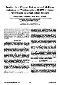
Fig. 2. Channel estimation flow diagram for each user in the proposed SWIFT framework.
D. Stopping Criterion As the proposed BS beam patterns do not adapt to any particular user, it is able to simultaneously estimate all downlink channels for multiple users. To this end, we propose that the BS continues to transmit pilot signals with randomly selected beamfoming vectors, until each user’s channel estimation has accurately converged. Recalling (22), we can assess the channel estimation convergence at the uth user by binarizing the estimated virtual channel vector as ( (u) (u,m) | < ΓσR 0, if |ˆ vi (u,m) = v¯i (23) 1, otherwise where Γ