1222
IEEE TRANSACTIONS ON POWER ELECTRONICS, VOL. 22, NO. 4, JULY 2007
FPGA-Based Adaptive Backstepping Sliding-Mode Control for Linear Induction Motor Drive Faa-Jeng Lin, Senior Member, IEEE, Chih-Kai Chang, and Po-Kai Huang
Abstract—A field-programmable gate array (FPGA)-based adaptive backstepping sliding-mode controller is proposed to control the mover position of a linear induction motor (LIM) drive to compensate for the uncertainties including the friction force. First, the dynamic model of an indirect field-oriented LIM drive is derived. Next, a backstepping sliding-mode approach is designed to compensate the uncertainties occurring in the motion control system. Moreover, the uncertainties are lumped and the upper bound of the lumped uncertainty is necessary in the design of the backstepping sliding-mode controller. However, the upper bound of the lumped uncertainty is difficult to obtain in advance of practical applications. Therefore, an adaptive law is derived to adapt the value of the lumped uncertainty in real time, and an adaptive backstepping sliding-mode control law is the result. Then, an FPGA chip is adopted to implement the indirect field-oriented mechanism and the developed control algorithms for possible low-cost and high-performance industrial applications. The effectiveness of the proposed control scheme is verified by some experimental results. With the adaptive backstepping sliding-mode controller, the mover position of the FPGA-based LIM drive possesses the advantages of good transient control performance and robustness to uncertainties in the tracking of periodic reference trajectories. Index Terms—Adaptive backstepping control, field-programmable gate array (FPGA), indirect field-oriented control, linear induction motor (LIM), sliding-mode control.
I. INTRODUCTION
A
linear induction motor (LIM) has many desirable performance features, including high-starting thrust force, no need for a gear between motor and the motion devices, the reduction of mechanical losses and the size of motion devices, high-speed operation, silence, and so on [1], [2]. Due to these advantages, LIMs have been widely used in industrial processes and transportation applications [3], [4]. The driving principles of an LIM are similar to those of a traditional rotary induction motor (RIM), but its control characteristics are more complicated than for an RIM, and the motor parameters are time varying due to changes in operating conditions, such as the speed of the mover, temperature, and rail configuration. Moreover, there are significant parameter variations in reaction rail resistivity, the dynamics of the air gap, slip frequency, phase unbalance, saturation of the magnetizing inductance, and end effects [2], [3]. Therefore, its mathematical model is difficult to
Manuscript received August 18, 2005; revised May 23, 2006. This work was supported by the National Science Council of Taiwan, R.O.C., under Grant NSC 94-2213-E-259-025. Recommended for publication by Associate Editor A. M. Trzynadlowski. The authors are with the Department of Electrical Engineering, National Dong Hwa University, Hualien 974, Taiwan, R.O.C. (e-mail:
[email protected]). Digital Object Identifier 10.1109/TPEL.2007.900553
derive completely. Considerable research has been performed on creating models of the dynamics of an LIM, which have taken many of the significant variations into consideration [1]–[5]. However, uncertainties still exist, including unpredictable plant parameter variations, external load disturbance, and unmodeled and nonlinear dynamics in practical applications of the LIM. Furthermore, since the operation of an LIM involves two contacting bodies, a friction force is inevitably among the forces of motion. In addition, this friction characteristic may be easily varied due to a change in normal forces in contact, and the temperature and humidity. In a closed-loop control system, the friction force results in a steady-state error, a limit cycle, and a low bandwidth [6], [7]. Unfortunately, friction is a natural phenomenon that is quite difficult to model, and it is not completely understood. Therefore, it is impossible to obtain a precise friction model for practical applications. On the other hand, the dynamic model of an LIM can be modified from the dynamic model of the RIM at a certain low speed since an LIM can be visualized as an unrolled RIM. Thus, field-orientated control [5], [8] can be adopted to decouple the dynamics of the thrust force and the flux amplitude of the LIM. A field-programmable gate array (FPGA) incorporates the architecture of gate arrays and the programmability of a programmable logic device (PLD). It consists of thousands of logic gates, some of which are combined together to form a configurable logic block (CLB), thereby simplifying high-level circuit design. Interconnections between logic gates using software are externally defined through static random-access memory (SRAM) and read-only memory (ROM), which will provide flexibility in modifying the designed circuit without altering the hardware. Moreover, concurrent operation, simplicity, programmability, comparatively low cost, and rapid prototyping make it the favorite choice for prototyping an application-specific integrated circuit (ASIC) [9], [10]. Furthermore, all of the internal logic elements and, therefore, all of the control procedures of the FPGA are executed continuously and simultaneously. The circuits and algorithms can be developed in the VHSIC hardware description language (VHDL) [9], [10]. This method is as flexible as any software solution. Another important advantage of VHDL is that it is technology independent. The same algorithm can be synthesized into any FPGA and even has a direct path to an ASIC, opening interesting possibilities in industrial applications in terms of performance and cost. However, the major disadvantage of an FPGA-based system for hardware implementation is the limited capacity of available cells. Therefore, only research on FPGA-based sliding-mode or fuzzy controllers can be found in high-performance control application literature [11]–[13]. On the other hand, FPGA-based applications of various motor
0885-8993/$25.00 © 2007 IEEE
LIN et al.: FPGA-BASED ADAPTIVE BACKSTEPPING SLIDING-MODE CONTROL
1223
drives can be found in [14]–[16]. A digital wheelchair controller was presented in [14]. The control process consists of command decoding, speed estimation, and speed serving. Through proper partitioning to concurrent blocks, the design complexity is reduced significantly for an FPGA. The concepts of car maneuvers, fuzzy logic control (FLC), and sensor-based behaviors were merged to implement human-like driving skills by an autonomous car-like mobile robot in [15]. Four kinds of FLCs are synthesized to accomplish the autonomous fuzzy behavior control. The implementation of the proposed control on an FPGA chip is addressed. In the past decade, research about adaptive backstepping control has been increased [17]–[20]. Adaptive backstepping is a systematic and recursive design methodology for nonlinear feedback control. This approach is based upon a systematic procedure for the design of feedback control strategies suitable for the design of a large class of feedback-linearizable nonlinear systems exhibiting constant uncertainty, and guarantees global regulation and tracking for the class of nonlinear systems transformable into the parametric-strict feedback form. The idea of backstepping design is to select recursively some appropriate functions of state variables as pseudocontrol inputs for lower dimension subsystems of the overall system. Each backstepping stage results in a new pseudocontrol design, expressed in terms of the pseudocontrol designs from preceding design stages. When the procedure terminates, a feedback design for the true control input is the result which achieves the original design objective by virtue of a final Lyapunov function, which is formed by summing up the Lyapunov functions associated with each individual design stage [18]. Moreover, owing to the robust control performance of adaptive backstepping control and sliding-mode control, many combined adaptive backstepping and sliding-mode control schemes have appeared for both linear and nonlinear systems [21]–[23]. The motivation of this study is to design a robust control scheme to confront the uncertainties that exist in an LIM drive including the friction force using an FPGA chip to allow possible low-cost and high-performance industrial applications. Due to its robustness and easy-to-be implemented nature, an adaptive backstepping sliding-mode position controller proposed in [5] is adopted in this study to control the mover position of an indirect field-oriented control LIM drive. The proposed control algorithms are realized on a 24-MHz FPGA (XC2V1000) with 1 million gate counts and 10240 flip-flops from Xilinx, Inc., using VHSIC hardware description language (VHDL). The design and implementation of the FPGA-based control IC will be described in detail. Compared with a digital signal processor (DSP) or a PC-based fuzzy controller, the merits of the FPGA-based fuzzy controller are parallel processing and small size in addition to low cost. Moreover, the developed VHDL code can be easily modified and implemented to control any type of ac motors as well.
an iron back for the return path of the magnetic flux. The primary and secondary form a single-sided LIM. Moreover, a simple linear encoder is adopted for the feedback of the mover position. The dynamic model of the LIM is modified from the traditional model of a three-phase, Y-connected induction motor in a synchronous rotating reference frame and can be described by the following differential equations [2], [5]:
II. INDIRECT FIELD-ORIENTED LINEAR INDUCTION MOTOR DRIVE The primary (mover) of the adopted three-phase LIM is simply a cut open and rolled flat rotary-motor primary. The secondary consists of a sheet conductor using aluminum with
(1)
(2) (3) (4) (5) where and winding resistance per phase; secondary resistance per phase referred primary; magnetizing inductance per phase; secondary inductance per phase; primary inductance per phase; synchronous linear velocity; mover linear velocity; d-axis and -axis secondary flux; d-axis and -axis primary current; d-axis and -axis primary voltage; secondary time constant; leakage coefficient; electromagnetic force; force constant; external force disturbance; total mass of the moving element; viscous friction and iron-loss coefficient; pole pitch; number of pole pairs. In an ideally decoupled induction motor, the secondary flux linkage axis is forced to align with the -axis. It follows that: (6) Using (6), the desired secondary flux linkage in terms of be found from (4) as
can
(7)
1224
IEEE TRANSACTIONS ON POWER ELECTRONICS, VOL. 22, NO. 4, JULY 2007
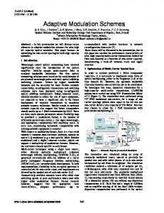
Fig. 1. System configuration of an LIM drive.
where is the Laplace operator. Moreover, using (3), the feedforward slip velocity signal can be estimated using as shown as follows: in (7) and (8) The block diagram of an indirect field-oriented LIM system is shown in Fig. 1, which consists of an LIM, a ramp comparison current-controlled pulsewidth-modulation (PWM) voltagesource inverter (VSI), an indirect field-oriented mechanism, a generator, where is the coordinate translator position of the secondary flux, a speed control loop, and a posi, and tion control loop. Three-phase current commands are generated from the coordinate translator for the ramp comparison current controller. The LIM used in this drive system is a three-phase Y-connected, two-pole 3 kW 60 Hz 180 V/14.2 A type. The detailed parameters of the LIM are
(9)
By use of the indirect field-oriented control technique and with the fact that the electrical time constant is much smaller than the mechanical time constant, the electromagnetic force shown in (5) can be reasonably represented by the following equations: (10) (11) The curve-fitting technique based on the step response is applied to find the drive model offline at the nominal case . The results are (on a scale of 14.9717 (m/s)/V)
(12) The “—” symbol represents the system parameters in the nominal condition. Though the electromagnetic force can be simplified as (10) via the field-oriented control, considering the variations of system parameters and external nonlinear and time-varying disturbance including friction force, the LIM
LIN et al.: FPGA-BASED ADAPTIVE BACKSTEPPING SLIDING-MODE CONTROL
1225
drive system is a nonlinear time-varying system in practical applications. III. ADAPTIVE BACKSTEPPING SLIDING-MODE CONTROL SYSTEM Considering a drive system with parameter variations, external force disturbance, and friction force for the actual LIM drive system, then
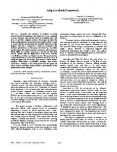
Fig. 2. Adaptive backstepping sliding-mode control system.
(13) (14) (15)
where is a positive constant. The first Lyapunov function is chosen as (22)
where and denote the uncertainties introduced and is the control input by system parameters is the friction force. Conto the motor drive system; and sidering Coulomb friction, viscous friction, and Stribeck effect, the friction force can be formulated as follows [6], [7]:
, then the derivative of
Define is
(23) Step 2) The derivative of
is now expressed as
(16) (24) where is the Coulomb friction; is the static friction; is is the coefficient of viscous the Stribeck velocity parameter; is a sign function. Reformulate (14), then friction; and (17) where
To design the backstepping control system, the lumped uncertainty is assumed to be bounded (i.e., ), and define the following Lyapunov function:
is called the lumped uncertainty and defined by
(25) (18)
The lumped uncertainty will be observed by an adaptive uncertainty estimator and assumed to be a constant during the observation. The above assumption is valid in practical digital processing of the observer since the sampling period of the observer is short enough compared with the variation of . The control objective is to design an adaptive backstepping of the system sliding-mode control system for the output , which shown in (15) to track the reference trajectory but also its is , asymptotically. Assume that not only are all bounded functions of first two derivatives time. The proposed adaptive backstepping sliding-mode control system is designed to achieve the position-tracking objective and is described step by step as follows. Step 1) For the position-tracking objective, define the tracking error as (19) and its derivative is (20) Define the following stabilizing function: (21)
with the sliding surface (26) Using (24) and (25), the derivative of rived as follows:
can be de-
(27) According to (27), a backstepping sliding-mode is designed as follows [5]: control law
(28) where and are positive constants. The detailed proof of stability can be found in [5]. According to the result of proof, the backstepping sliding-mode control system is asymptotically stable even if parametric uncertainty, external force disturbance, and friction force exist.
1226
IEEE TRANSACTIONS ON POWER ELECTRONICS, VOL. 22, NO. 4, JULY 2007
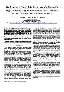
Fig. 3. Block diagram of the FPGA-based control system.
Step 3) Since the lumped uncertainty is unknown in practical application, the upper bound is difficult to determine; therefore, an adaptive law is proposed to adapt the value of the lumped uncertainty . Then, a Lyapunov candidate is chosen as (29) where and are positive constants. Taking the derivative of the Lyapunov function and using (28), then
The adaptation laws for [5]:
are designed as follows (32)
The detailed proof of stability can also be found in [5]. The designed adaptive backstepping slidingmode control system is shown in Fig. 2. Using the adaptive backstepping sliding-mode control design, the velocity and acceleration of the reference trajectory feedforward naturally resulted in superior tracking performance. IV. CIRCUITS DESIGN ON AN FPGA CHIP
(30) According to (38), an adaptive backstepping slidingis proposed as follows [5]: mode control law
(31)
The block diagram of the FPGA-based control system for an LIM drive using the current-controlled technique is shown in Fig. 3. The current-controlled PWM voltage-source inverter (VSI) is implemented by an intelligent power module (IPM) switching component (MUBW30-06A7) manufactured by IXYS Co. with a switching frequency of 15 kHz. The timing control module, encoder interface module, the field-oriented control module, and adaptive backstepping sliding-mode control module are realized on the FPGA chip. Three-phase current , and are generated from the coordinate commands translator and sent to three digital-to-analog converters (DACs) for the ramp comparison current control. The adopted DACs V. There is a are 12 b in size with an output voltage of
LIN et al.: FPGA-BASED ADAPTIVE BACKSTEPPING SLIDING-MODE CONTROL
1227
4-b control bus and 8-b data bus between the FPGA and DAC. Multiplexing is implemented in the data bus to form the 12-b data. The 12-b data are divided into a least significant 8-b latch and a most significant 4-b latch. The 4-b control bus controls the loading of data to the input latches of the DAC. The entire input/output (I/O) port of this chip includes two pins for the input ports and 36 pins for the output port. Moreover, 3322 out of 10240 flip-flops (32%) have been used in the FPGA chip. A. Encoder Interface Module The block diagram of the encoder interface module is shown in Fig. 4(a), which consists of timing control, two digital filters, a decoder, an up–down counter, two clock (CLK) generators, a register, a command generator, and one adder. The function of the encoder interface is to obtain the position and speed values of the mover. The resolutions of the encoder are digital value and digital value at the samm/s is pling frequency 732 Hz. The scaling obtained since the specification is designed as digital value. The pulse-count signal PLS and the rotating direction signal DIR are obtained using the A, B pulse input signals from the decoder through two digital filters. The position signal can be obtained using the PLS and DIR signals through an up–down counter. Moreover, the command generator includes periodic sinusoidal intellectual property (IP) and periodic trapezoidal IP in order to generate the position command . Furthermore, is the velocity signal, and results from the difference between the . position signal and the time delay of B. Field-Oriented Control Module The field-oriented control module shown in Fig. 4(b) is composed of a generator, a coordinate translator, a and generator and timing control. The is obtained using the based on (8), the control effort estimated slip velocity signal signal , the velocity signal , and an integrator. Then, and signals are obtained through the and generator. Moreover, three-phase current commands , and are generated from the coordinate translator, which consists of six multipliers and five adders, and sent to three DACs for the ramp comparison current controller. Each DAC needs 12 pins in the output port. All of the multipliers and adders use 12 by 12-b 2’s compliment signed arithmetic with sequential clock control using the timing control module. C. Adaptive Backstepping Sliding-Mode Control Module The block diagram of an adaptive backstepping sliding-mode control module is shown in Fig. 4(c). Using (31), the adaptive backstepping sliding-mode control law is designed as
(33) where is the digital value and is the digital value. To implement the control law effectively, the above equation can be divided into the fol, where and lowing six parts: 1)
Fig. 4. Circuits design on an FPGA. (a) Encoder interface module. (b) Field-oriented control module. (c) Adaptive backstepping sliding-mode control module. (d) Sliding layer module.
, two multipliers, four adders, and a reg, ister are needed to implement this part; 2) , a multiplier and an adder are needed to imwhere plement this part; 3) , two multipliers, an adder, an integrator, and a register are needed to implement this part, and the integrator is implemented using an accumulator; 4) , this part is implemented using the result of with
1228
IEEE TRANSACTIONS ON POWER ELECTRONICS, VOL. 22, NO. 4, JULY 2007
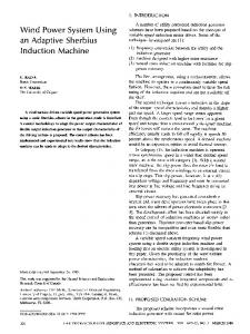
Fig. 5. Experimental results of backstepping sliding-mode control system for periodic sinusoidal command. (a) Mover position at the nominal condition. (b) Control effort at the nominal condition. (c) Mover position at the parameter variation condition. (d) Control effort at the parameter variation condition.
Fig. 6. Experimental results of the backstepping sliding-mode control system for periodic trapezoidal command. (a) Mover position at the nominal condition. (b) Control effort at the nominal condition. (c) Mover position at the parameter variation condition. (d) Control effort at the parameter variation condition.
an adder and a register; 5) , this part is implemented using the with an adder and a register; 6) , result of where , this part is implemented using the result of the sliding layer module with an adder and a multiplier.
and are positive constants. The sliding layer module and is shown in Fig. 4(d). A multiplier, an adder, a divider, a comparator, and a multiplexer are needed to implement (34). V. EXPERIMENTAL RESULTS
D. Sliding Layer Module To avoid the chattering phenomena, the sign fuction in the adaptive backstepping sliding-mode control is replaced by the following saturated function: (34) where
The digital values of the parameters of the adaptive backstepping sliding-mode controller are given as follows:
(35) These parameters are chosen to achieve the best transient control performance in the experimentation considering the requirement of stability and possible operating conditions. The control objective is to control the mover to move periodically ac-
LIN et al.: FPGA-BASED ADAPTIVE BACKSTEPPING SLIDING-MODE CONTROL
Fig. 7. Experimental results of the adaptive backstepping sliding-mode control system for periodic sinusoidal command at the nominal condition. (a) Mover position. (b) Control effort. (c) Estimated value of lumped uncertainty.
cording to reference trajectories. Two test conditions are provided, which are the nominal condition and the parameter variation condition. In the experimentation, the parameter variation condition is the addition of one iron disk, weighing 9.37 kg to the mass of the mover. Some experimental results are provided to demonstrate the effectiveness of the proposed FPGA-based control system. First, the experimental results of the backstepping sliding-mode conset to be 4 are depicted in Figs. 5 and 6 trol system with for the comparison of the control performance. The tracking responses due to a periodic sinusoidal command at the nominal condition and parameter variation condition are depicted in Fig. 5(a) and (c); the associated control efforts are depicted in Fig. 5(b) and (d). Moreover, the tracking responses due to a periodic trapezoidal command at the nominal condition and parameter variation condition are depicted in Fig. 6(a) and (c); the associated control efforts are depicted in Fig. 6(b) and (d). From the experimental results, the degraded tracking responses shown in Fig. 5(c) and 6(c) are induced by the inappropriate selection of lumped uncertainty bound. Although a large bound value of the lumped uncertainty can be selected to confront the uncertainties that exist in practical applications, it will result in large chattering phenomena in the control effort. Now, the adaptive backstepping sliding-mode control system is implemented
1229
Fig. 8. Experimental results of the adaptive backstepping sliding-mode control system for periodic sinusoidal command at the parameter variation condition. (a) Mover position. (b) Control effort. (c) Estimated value of lumped uncertainty.
to control the mover position of the LIM drive. The experimental results of the tracking responses, control efforts, and estimation of the lumped uncertainty due to periodic sinusoidal command at the nominal condition and parameter variation condition are depicted in Figs. 7 and 8. Furthermore, the experimental results of the tracking responses, control efforts, and estimation of the lumped uncertainty due to periodic trapezoidal command at the nominal condition and parameter variation condition are depicted in Figs. 9 and 10. Compared with the experimental results of the backstepping sliding-mode control system shown in Figs. 5(c) and 6(c), the degraded tracking responses are improved as shown in Figs. 8(a) and 10(a) using the adaptive backstepping sliding-mode control scheme at the parameter variation condition. In addition, the nonzero estimated values of the lumped uncertainty at the nominal condition shown in Figs. 7(c) and 9(c) are induced by the friction force and unmodelled uncertainty in practical applications. From the experimental results, the robust control performance of the proposed FPGA-based adaptive backstepping sliding-mode control system under the occurrence of parameter variations at different trajectories is obvious, owing to the online adjustment of the value of the lumped uncertainty.
1230
IEEE TRANSACTIONS ON POWER ELECTRONICS, VOL. 22, NO. 4, JULY 2007
Fig. 9. Experimental results of the adaptive backstepping sliding-mode control system for periodic trapezoidal command at the nominal condition. (a) Mover position. (b) Control effort. (c) Estimated value of lumped uncertainty.
VI. CONCLUSION This study has successfully demonstrated the design and implementation of an FPGA-based adaptive backstepping sliding-mode control system for the position control of the mover of an LIM drive system. First, the dynamic model of an indirect field-oriented LIM drive was introduced. Then, a backstepping sliding-mode control technique was designed. However, the upper bound of the lumped uncertainty is necessary in the design of the backstepping sliding-mode controller. To relax the requirement for the upper bound of the lumped uncertainty, an adaptive backstepping sliding-mode controller with an adaptive mechanism to adapt the lumped uncertainty in real time was proposed. The proposed FPGA-based adaptive backstepping sliding-mode control system is robust for parameter variations, external force disturbances, and friction force at different trajectories. Finally, the effectiveness of the proposed low-cost, high-performance FPGA-based LIM drive has been confirmed by some experimental results. The major contributions of this study are: 1) the successful implementation of the indirect field-oriented mechanism and adaptive backstepping sliding-mode controller in an FPGA chip and 2) the successful application of the FPGA-based controller
Fig. 10. Experimental results of the adaptive backstepping sliding-mode control system for periodic trapezoidal command at the parameter variation condition. (a) Mover position. (b) Control effort. (c) Estimated value of lumped uncertainty.
to control the mover position of an LIM with robust control performance. REFERENCES [1] I. Takahashi and Y. Ide, “Decoupling control of thrust and attractive force of a LIM using a space vector control inverter,” IEEE Trans. Ind. Appl., vol. 29, no. 1, pt. 1, pp. 161–167, Jan./Feb. 1993. [2] I. Boldea and S. A. Nasar, Linear Electric Actuators and Generators. Cambridge, U.K.: Cambridge Univ. Press, 1997. [3] Z. Zhang, T. R. Eastham, and G. E. Dawson, “Peak thrust operation of linear induction machines from parameter identification,” in Proc. IEEE Ind. Appl. Soc., 1995, pp. 375–379. [4] P. Cancelliere, V. D. Colli, and F. Marignetti, “Nonlinear feedback control for linear induction motor using a speed insensitive slidingmode state observer,” presented at the 4th Int. Symp. Linear Drives for Industry Applications, 2003, CO-09. [5] F. J. Lin, P. H. Shen, and S. P. Hsu, “Adaptive backstepping sliding mode control for linear induction motor drive,” Proc. Inst. Elect. Eng., Electr. Power Appl., vol. 149, no. 3, pp. 184–194, 2002. [6] S. Sankaranarayanan and F. Khorrami, “Adaptive variable structure control and applications to friction compensation,” in Proc. IEEE CDC Conf. Rec., 1997, pp. 4159–4164. [7] A. P. Maulana, H. Ohmori, and A. Sano, “Friction compensation strategy via smooth adaptive dynamic surface control,” in Proc. IEEE CCA Conf. Rec., 1999, pp. 1090–1095. [8] D. W. Novotny and T. A. Lipo, Vector Control and Dynamics of AC Drives. Oxford, U.K.: Clarendon Press, 1996.
LIN et al.: FPGA-BASED ADAPTIVE BACKSTEPPING SLIDING-MODE CONTROL
1231
[9] K. Skahill, VHDL for Programmable Logic. Reading, MA: AddisonWesley, 1996. [10] H. C. Roth, Digital Systems Design Using VHDL. Boston, MA: PWS, 1998. [11] J. Chen and P. C. Tang, “A sliding mode current control scheme for PWM brushless DC motor drives,” IEEE Trans. Power Electron., vol. 14, no. 3, pp. 541–551, May 1999. [12] R. R. Ramos, D. Biel, E. Fossas, and F. Guinjoan, “A fixed-frequency quasi-sliding control algorithm: application to power inverters design by means of FPGA implementation,” IEEE Trans. Power Electron., vol. 18, no. 1, pt. 2, pp. 344–355, Jan. 2003. [13] D. Kim, “An implementation of fuzzy logic controller on the reconfigurable FPGA system,” IEEE Trans. Ind. Electron., vol. 47, no. 3, pp. 703–715, Jun. 2000. [14] R. X. Chen, L. G. Chen, and L. Chen, “System design consideration for digital wheelchair controller,” IEEE Trans. Ind. Electron., vol. 47, no. 4, pp. 898–907, Aug. 2000. [15] T. S. Li, S. J. Chang, and Y. X. Chen, “Implementation of humanlike driving skills by autonomous fuzzy behavior control on an FPGAbased car-like mobile robot,” IEEE Trans. Ind. Electron., vol. 50, no. 5, pp. 867–880, Oct. 2003. [16] H. Abu-Rub, J. Guzinski, Z. Krzeminski, and H. A. Toliyat, “Speed observer system for advanced sensorless control of induction motor,” IEEE Trans. Energy Convers., vol. 18, no. 2, pp. 219–224, Jun. 2003. [17] M. Krstic, I. Kanellakopoulos, and P. V. Kokotovic, Nonlinear and Adaptive Control Design. New York: Wiley, 1995. [18] D. G. Taylor, “Nonlinear control of electric machines: An overview,” IEEE Control Syst. Mag., vol. 14, no. 6, pp. 41–51, Dec. 1994. [19] H. J. Shieh and K. K. Shyu, “Nonlinear sliding-mode torque control with adaptive backstepping approach for induction motor drive,” IEEE Trans. Ind. Electron., vol. 46, no. 2, pp. 380–389, Apr. 1999. [20] F. J. Lin and C. C. Lee, “Adaptive backstepping control for linear induction motor drive to track period references,” in Proc. Inst. Elect. Eng., Electr. Power Appl., 2000, vol. 147, no. 6, pp. 449–458. [21] A. Stotsky, J. K. Hedrick, and P. P. Yip, “The use of sliding modes to simplify the backstepping control method,” in Proc. Amer. Control Conf., 1997, pp. 1703–1708. [22] M. Rios-Bolivar and A. S. I. Zinober, “Dynamical adaptive sliding mode control of observable minimum-phase uncertain nonlinear systems,” in Variable Structure Systems, Sliding Mode and Nonlinear Control. London, U.K.: Springer-Verlag, 1999, pp. 211–235. [23] G. Bartolini, A. Ferrara, L. Giacomini, and E. Usai, “Properties of a combined adaptive/second-order sliding mode control algorithm for some classes of uncertain nonlinear systems,” IEEE Tran. Autom. Control, vol. 45, no. 7, pp. 1334–1341, Jul. 2000.
Faa-Jeng Lin (M’93–SM’99) received the B.S. and M.S. degrees in electrical engineering from the National Cheng Kung University, Tainan, Taiwan, R.O.C., in 1983 and 1985, respectively, and the Ph.D. degree in electrical engineering from the National Tsing Hua University, Hsinchu, Taiwan, in 1993. From 1993 to 2001, he was an Associate Professor and then a Professor in the Department of Electrical Engineering, Chung Yuan Christian University, Chung Li. From 2001 to 2003, he was Chairperson and a Professor in the Department of Electrical Engineering, National Dong Hwa University, Hualien. From 2003 to 2005, he was Dean of Research and Development, National Dong Hwa University, where he is currently Dean of Academic Affairs. His research interests include ac and ultrasonic motor drives, digital-signal-processor (DSP)-based computer control systems, fuzzy and neural-network control theories, nonlinear control theories, power electronics, and micromechatronics. Prof. Lin received the Outstanding Research Professor Award from the Chung Yuan Christian University in 2000; the Excellent Young Electrical Engineer Award from the Chinese Electrical Engineering Association, Taiwan, in 2000; the Crompton Premium Best Paper Award from the Institution of Electrical Engineers (IEE), U.K., in 2002; the Outstanding Research Award from the National Science Council, Taiwan, in 2004; the Outstanding Research Professor Award from the National Dong Hwa University in 2004. He was the recipient of the Outstanding Professor of Electrical Engineering Award from the Chinese Electrical Engineering Association, Taiwan, in 2005.
Chih-Kai Chang was born in Kaohsiung, Taiwan, R.O.C., in 1981. He received the B.S. and M.S. degrees in electrical engineering from National Dong Hwa University, Hualien, Taiwan, in 2004 and 2006, respectively. His research interests include nonlinear control theories, artificial intelligence control theories, and field-programmable gate arrays (FPGAs).
Po-Kai Huang was born in Taipei, Taiwan, R.O.C., in 1979. He received the B.S. and M.S. degrees in electrical engineering from Chung Yuan Christian University, Chung Li, Taiwan, in 2001 and 2003, respectively, and the Ph.D. degree in electrical engineering from National Dong Hwa University, Hualien, in 2006. His research interests include alternating current motor drives, artificial-intelligence control theories, and micromechatronics.