based system on AdaBoost algorithm using Haar features. We describe the ... Verilog HDL and implemented in Xilinx Virtex-5 FPGA. Its performance has been ... Only a few papers have addressed a hardware design and implement of real- ... Permission to make digital or hard copies of all or part of this work for personal or ...
FPGA-Based Face Detection System Using Haar Classifiers †
Junguk Cho†
Shahnam Mirzaei‡
Department of Computer Science and Engineering University of California, San Diego La Jolla, CA 92093, United States
{jucho, kastner}@cs.ucsd.edu ABSTRACT This paper presents a hardware architecture for face detection based system on AdaBoost algorithm using Haar features. We describe the hardware design techniques including image scaling, integral image generation, pipelined processing as well as classifier, and parallel processing multiple classifiers to accelerate the processing speed of the face detection system. Also we discuss the optimization of the proposed architecture which can be scalable for configurable devices with variable resources. The proposed architecture for face detection has been designed using Verilog HDL and implemented in Xilinx Virtex-5 FPGA. Its performance has been measured and compared with an equivalent software implementation. We show about 35 times increase of system performance over the equivalent software implementation.
Categories and Subject Descriptors C.3 [Special-Purpose and Application-Based Systems]: RealTime and Embedded Systems
General Terms Design, Experimentation, Measurement, Performance
Keywords AdaBoost, architecture, face detection, FPGA, Haar classifier, image processing, real-time
1. INTRODUCTION Face detection in image sequence has been an active research area in the computer vision field in recent years due to its potential applications such as monitoring and surveillance [1], human computer interfaces [2], smart rooms [3], intelligent robots [4], and biomedical image analysis [5]. Face detection is based on identifying and locating a human face in images regardless of size, position, and condition. Numerous approaches have been proposed for face detection in images. Simple features such as color, motion, and texture are used for the face detection in early researches. However, these methods break down easily because of the complexity of the real world. Face detection proposed by Viola and Jones [6] is most popular among the face detection approaches based on statistic methods. This face detection is a variant of the AdaBoost algorithm [7] which achieves rapid and Permission to make digital or hard copies of all or part of this work for personal or classroom use is granted without fee provided that copies are not made or distributed for profit or commercial advantage and that copies bear this notice and the full citation on the first page. To copy otherwise, or republish, to post on servers or to redistribute to lists, requires prior specific permission and/or a fee. FPGA'09, February 22-24, 2009, Monterey, California, USA. Copyright 2009 ACM 978-1-60558-410-2/09/02...$5.00.
‡
Jason Oberg‡
Ryan Kastner†
Department of Electrical and Computer Engineering University of California, Santa Barbara Santa Barbara, CA93106, United States
{shahnam, jason_oberg}@umail.ucsb.edu robust face detection. They proposed a face detection framework based on the AdaBoost learning algorithm using Haar features. However, the face detection requires considerable computation power because many Haar feature classifiers check all pixels in the images. Although real-time face detection is possible using high performance computers, the resources of the system tend to be monopolized by face detection. Therefore, this constitutes a bottleneck to the application of face detection in real time. Almost all of the available literatures on real-time face detection are theoretical or describe a software implementation. Only a few papers have addressed a hardware design and implement of realtime face detection. Theocharides et al. [8] presented the implementation of neural network based face detection in an ASIC to accelerate processing speed. However, VLSI technology requires a large amount of development time and cost. Also it is difficult to change design. McCready [9] designed and implemented face detection for the Transmogrifier-2 configurable hardware system. This implementation utilized nine FPGA boards. Sadri et al. [10] implemented neural network based face detection on the Virtex-II Pro FPGA. Skin color filtering and edge detection are used to reduce the processing time. However, some operations are implemented on hardcore PowerPC processor with embedded software. Wei et al. [11] presented FPGA implementation for face detection using scaling input images and fixed-point expressions. However, the image size is too small (120×120 pixels) to be practical and only some parts of classifier cascade are actually implemented. A low-cost detection system was implemented using Cyclone II FPGA by Yang et al. [12]. The frame rate of this system is 13 fps with low detection rate of about 75%. Nair et al. [13] implemented an embedded system for human detection on an FPGA. It can process the images at speeds of 2.5 fps with about 300 pixels images. Gao et al. [14] presented an approach to use an FPGA to accelerate the Haar feature classifier based face detection. They re-trained the Haar classifier with 16 classifiers per stage. However, only classifiers are implemented in the FPGA. The integral image generation and detected face display are processed in a host microprocessor. Also the largest Virtex-5 FPGA was used for the implementation because the design size is too large. Hiromoto et al. [15] implemented real-time object detection based on the AdaBoot algorithm. They proposed hybrid architecture of a parallel processing module for the former stages and a sequential processing module for the subsequent stages in the cascade. Since the parallel processing module and the sequential processing module are divided after evaluating a processing time with fixed Haar feature data, it should be designed and implemented again in order to apply new Haar feature data. Also the experimental result and analysis of the implemented system are not discussed.
In this paper, we present a hardware architecture for real-time face detection system. We propose hardware design techniques to accelerate the processing speed of face detection. The face detection system generates an integral image window to perform a Haar feature classification during one clock cycle. And then it performs classification operations in parallel using Haar classifiers to detect a face in the image sequence. The main contribution of our work, described in this paper, is design and implementation of a physically feasible hardware system to accelerate the processing speed of the operations required for realtime face detection. Therefore, this work has resulted in the development of a real-time face detection system employing an FPGA implemented system designed by Verilog HDL. Its performance has been measured and compared with an equivalent software implementation. This paper is organized as follows: In Section 2, we explain the face detection algorithm. In Section 3, we describe the architecture, designed with Verilog HDL, of a face detection system using block diagrams. In Section 4, we show the implementation of the real-time face detection system in an FPGA and measure the corresponding performance. Finally, we conclude in Section 5.
2. FACE DETECTION ALGORITHM The face detection algorithm proposed by Viola and Jones is used as the basis of our design. The face detection algorithm looks for specific Haar features of a human face. When one of these features is found, the algorithm allows the face candidate to pass to the next stage of detection. A face candidate is a rectangular section of the original image called a sub-window. Generally these sub-windows have a fixed size (typically 24×24 pixels). This sub-window is often scaled in order to obtain a variety of different size faces. The algorithm scans the entire image with this window and denotes each respective section a face candidate [6]. The algorithm uses an integral image in order to process Haar features of a face candidate in constant time. It uses a cascade of stages which is used to eliminate non-face candidates quickly. Each stage consists of many different Haar features. Each feature is classified by a Haar feature classifier. The Haar feature classifiers generate an output which can then be provided to the stage comparator. The stage comparator sums the outputs of the Haar feature classifiers and compares this value with a stage threshold to determine if the stage should be passed. If all stages are passed the face candidate is concluded to be a face. These terms will be discussed in more detail in the following sections.
2.1 Integral Image The integral image is defined as the summation of the pixel values of the original image. The value at any location (x, y) of the integral image is the sum of the image’s pixels above and to the left of location (x, y). Figure 1 illustrates the integral image generation.
Figure 1. Integral image generation. The shaded region represents the sum of the pixels up to position (x, y) of the image. It shows a 3×3 image and its integral image representation.
Figure 2. Examples of Haar features. Areas of white and black regions are multiplied by their respective weights and then summed in order to get the Haar feature value. by their respective weights, and then summing the results. The area of each rectangle is easily found using the integral image. The coordinate of the any corner of a rectangle can be used to get the sum of all the pixels above and to the left of that location using the integral image. By using each corner of a rectangle, the area can be computed quickly as denoted by Figure 3. Since L1 is subtracted off twice it must be added back on to get the correct area of the rectangle. The area of the rectangle R, denoted as the rectangle integral, can be computed as follows using the locations of the integral image: L4-L3-L2+L1
2.3 Haar Feature Classifier A Haar feature classifier uses the rectangle integral to calculate the value of a feature. The Haar feature classifier multiplies the weight of each rectangle by its area and the results are added together. Several Haar feature classifiers compose a stage. A stage comparator sums all the Haar feature classifier results in a stage and compares this summation with a stage threshold. The threshold is also a constant obtained from the AdaBoost algorithm. Each stage does not have a set number of Haar features. Depending on the parameters of the training data individual stages can have a varying number of Haar features. For example, Viola and Jones’ data set used 2 features in the first stage and 10 in the second. All together they used a total of 38 stages and 6060 features [6]. Our data set is based on the OpenCV data set which used 22 stages and 2135 features in total [16][17].
2.2 Haar Features Haar features are composed of either two or three rectangles. Face candidates are scanned and searched for Haar features of the current stage. The weight and size of each feature and the features themselves are generated using a machine learning algorithm from AdaBoost [6][7]. The weights are constants generated by the learning algorithm. There are a variety of forms of features as seen below in Figure 2. Each Haar feature has a value that is calculated by taking the area of each rectangle, multiplying each
Figure 3. Calculating the area of a rectangle R is done using the corner of the rectangle: L4-L3-L2+L1.
2.4 Cascade The Viola and Jones face detection algorithm eliminates face candidates quickly using a cascade of stages. The cascade eliminates candidates by making stricter requirements in each stage with later stages being much more difficult for a candidate to pass. Candidates exit the cascade if they pass all stages or fail any stage. A face is detected if a candidate passes all stages. This process is shown in Fig 4.
3. IMPLEMENTATION 3.1 System Overview We proposed an architecture for a real-time face detection system. Figure 5 shows the overview of the proposed architecture for face detection. It consists of seven modules: image interface, frame grabber, image store, image scaler, classifier, display, and DVI interface. The image interface and DVI interface are implemented using ASIC custom chips with the FPGA board. The others are designed using Verilog HDL and implemented in an FPGA in order to perform face detection in real-time.
3.2 Architecture for Face Detection
Figure 4. Cascade of stages. Candidate must pass all stages in the cascade to be concluded as a face.
3.2.3 Image Scaler The images are scaled down based on a scale factor by the image scaler module. The image scaler module generates and transfers the address of the BRAM containing a frame image in the image store module to request image data according to a scale factor. The image store module transfers a pixel data to the classifier module based on the address of BRAM required from the image scaler module.
3.2.4 Classifier
3.2.1 Frame Grabber In frame grabber module, the frame grabber controller generates the control signals for controlling the A/D converter which converts the analog image signals into digital image data, and the sync separator which generates the image sync signals in the image interface module. The image sync signal and the color image data are transferred from the image interface module. The image cropper crops the images based on the sync signals. These image data and sync signals are used in all of the modules of the face detection system.
3.2.2 Image Store The image store module stores the image data arriving from the frame grabber module frame by frame. This module transfers the image data to the classifier module based on the scale information from the image scaler module. The image of a frame is stored in a BRAM of the FPGA.
The classifier module performs the classification for the face detection using Haar feature data. This module consists of the image line buffer, image window buffer, integral image window buffer, feature classifier, stage comparator, and feature training data. The face detection is performed by the Haar feature classification using an integral image. The integral image generation requires substantial computation. A general purpose computer of Von Neumann architecture has to access image memory at least width × height times to get the value of each pixel when it processes an image with width × height pixels. It may take a long latency delay every frame. In order to reduce memory access and processing time, we propose a specific architecture for the integral image generation. This architecture stores the necessary pixels for processing each pixel and its neighboring pixels together. It consists of the image line buffer, image window buffer, and integral image window buffer. Each buffer has its own
Figure 5. Block diagram of proposed face detection system.
controller. The image line buffer stores some parts of the image and its controller generates the control signals for moving and storing the pixel values. The image line buffer uses dual port BRAMs where the number of BRAMs is the same as that of the row in the image window buffer. Each dual port BRAM can store one line of an image. Thus, the x-coordinates of the pixels can be used as the address for the dual port BRAM. For the incoming pixel where the coordinate is (x, y), the image line buffer controller performs operations such as in (1), where n is the image window row size, p(x, y) is the incoming pixel value, and L(x, y) represents each pixel in the image line buffer. ,
,
,
,
1 , where 1
2
(1)
0
, where
With these operations, the pixel values in the lines of an image are stored in dual port BRAMs. Since each dual port BRAM stores one line of an image, it is possible to get one pixel value from every line simultaneously. The image window buffer stores pixel values moving from the image line buffer and its controller generates control signals for moving and storing the pixel values. Since pixels of an image window buffer are stored in registers, it is possible to access all pixels in the image window buffer simultaneously to generate the integral image window. For the incoming pixel with coordinate (x, y), the image window buffer controller performs operation as in (2) where n and m are the row and column size of the image window buffer, respectively. p(i, j) is the incoming pixel value in the image window buffer; p(x, y) is the incoming pixel value; I(i, j) represents each of the pixels in the image window buffer; and L(x, y) represents each of the pixels in the image line buffer. , ,
, ,
when
1 , , where 1 1 , where 1 , 1, 1
,
, where 1, 0
1
(2)
1 0, 2,
2 ,
,
1 ,
1 ,
1
The integral image window buffer stores integral pixel values moving from the image window buffer and its controller generates control signals for moving and calculating the integral pixel values. Since pixels of an integral image window buffer are stored in registers, it is possible to access all integral pixels in the integral image window buffer simultaneously to perform the Haar feature classification. For incoming pixel with coordinate (i, j), the integral image window buffer controller performs operation as in (3) where n is the row and column size of the integral image window buffer. II(s, t) represents each of the integral pixels in the integral image window buffer; and I(i, j) represents each of the pixels in the image window buffer. ,
(3) ,
where 0 0
, 1, 0
2 1,
1
1 , 2 2,
,
1
Figure 6 shows all of the actions in the proposed architecture to generate the integral image. For every image from the frame grabber module, the integral image window buffer is calculated to perform the feature classification using the integral image. A Haar classifier consists of two or three rectangles and their weight values, feature threshold value, and left and right values. Each rectangle presents four points using the coordinates (x, y) of most left and up point, width w, and height h as shown in Figure 7. The integral pixel value of each rectangle can be calculated using these points from the integral image window buffer as shown in Figure 8. Since integral pixel values in an integral image window buffer are stored in registers, it is possible to access all integral pixel values in the integral image window buffer simultaneously to calculate the integral image value of the rectangles of the Haar feature classifier. It enables us to save the memory access time. Figure 9 shows the architecture of a Haar classifier for face detection. All Haar feature data are stored in the BRAMs. Four points of the rectangles of the Haar feature classifer are calculated
Figure 6. Architecture for generating integral image window.
Figure 7. Rectangle calculation of Haar feature classifier.
Figure 8. Simultaneous access to integral image window in order to calculate integral image of Haar feature classifiers.
Figure 9. Architecture for performing Haar feature classification.
by the method as shown in Figure 7. The integral image values of Haar classifier are obtained from the integral image window buffer as shown in Figure 8. Integral image value of each rectangle multiplies with its weight. The summation of all integral image values multiplied by their weight is the result of one Haar feature classifier. This result is compared with the feature threshold. If the result is smaller than the feature threshold, the final resultant value of this Haar classifier is the left value. Otherwise, the final resultant value is the right value. This final resultant value is accumulated during the same stage. The accumulative value of the stage is compared with the stage threshold. If the accumulative value is larger than the stage threshold, it goes to the next stage and so on to decide if this image window could pass all stages. The proposed architecture of the Haar classifier is implemented based on a pipeline scheme as shown in Figure 9. During each clock cycle, the integral pixel values of Haar classifier from the integral image window buffer and the parameters of Haar classifier from the Haar feature BRAMs are fed to calculate the result of classification continuously. The latency for the first Haar classifier is five clock cycles.
frontal human faces based on the Viola and Jones algorithm [16][17]. This cascade Haar feature training data are trained by frontal faces whose size are 20x20, that includes a total of 22 stages, 2135 Haar classifiers, and 4630 Haar features. Table 1 shows the number of Haar classifiers in each stage. In the proposed face detection system as shown in Figure 5, the face detection is performed in three major parts. The first part is grabbing and scaling. This part consists of the frame grabber, image store, and image scaler modules. These modules are for grabbing images and generating scaled images. Sub-windows for the Haar classifier are expanded to detect large objects in Viola and Jones object detection algorithm. Since the Haar feature classifier consists of simple rectangles, scaling a sub-window is not hard. Therefore, this method is widely used for software object detection implementation. However, the larger cache memory of the integral image is required according to the larger size of a sub-window to achieve fast memory access, which is difficult to implement in hardware. A scaling image technique is used in hardware instead of the scaling sub-window because it does not need a huge cache memory for fast memory access and it is easy to implement in hardware. Since our architecture has a
3.2.5 Display In the display module, the Digital Visual Interface (DVI) specification is applied to display the image sequence to the LCD monitor through a DVI transmitter in the DVI interface module. This module generates the sync signals and image data for the DVI transmitter using the image signals and image data from the other modules.
3.3 FPGA Implementation The proposed architecture for face detection has been designed using Verilog HDL and implemented in Xilinx Virtex-5 FPGA. We use the Haar feature training data from OpenCV to detect the
Table 1. Number of weak classifiers in each stage Stage # 0 1 2 3 4 5 6 7
# of Classifier 3 16 21 39 33 44 50 51
Stage # 8 9 10 11 12 13 14 15
# of Classifier 56 71 80 103 111 102 135 137
Stage # 16 17 18 19 20 21
# of Classifier 140 160 177 182 211 213
Total
2135
fixed integral image window (21×21 pixels), it needs to scale input images down to detect large faces. To make scaled images, we use a nearest neighbor interpolation algorithm with a factor of 1.2. A pixel value in the scaled images is set to the value of the nearest pixel in the original images. This is the simplest interpolation algorithm that requires a lower computation cost. The number of the scaled images depends on the input image resolution. Our scaler module performs the down-scaling of input images until the height of the scaled image is similar with the size of the image window (21x21 pixels). The scaler module for 320×240 pixels images has 14 scale factors (1.20~1.213), the scaler module for 640×480 pixels images has 18 scale factors (1.20~1.217). The second part is classifying to perform Haar feature classification using the integral image. This part consists of a classifier module which has the image line buffer, image window buffer, integral image window buffer, feature classifier, stage comparator, and feature training data blocks. Since generating integral image of the whole scaled image requires substantial computation power and time, we generate the integral image of only the current image window. The image line buffer (20 lines), image window buffer (21×41 cells), and integral image window buffer (21×21 cells) are implemented to generate the integral image of the current window during one clock cycle. The pixel data are stored and moved in the image line buffer according to the mechanism of the architecture explained in the previous section. The pixel data with the same address of the image line buffer are transferred to the image window buffer simultaneously. The image window buffer performs pre-calculation to generate the integral image widow. The image window buffer has two parts: The first part (21x20 cells) calculates the accumulation values of each column of the image window buffer. Each column has only one adder. The adder of the most left column calculates the summation of first row and second row pixel values in the most left column. The adder of the second left column calculates the summation of the first, second, and third row pixel values in the second left column. Finally, the adder of 20th column calculates the summation of all pixel values in the 20th column. The pipeline scheme is applied in this part, so the latency of first summation of all pixel values in the 20th column is 20 clock cycles. The second part (21x22 cells) latches and moves the accumulative pixel values of the column to the adjacent column. The accumulated pixel values are used to generate the integral image window. The integral image window buffer calculates the integral image of the current image window. Each element of the integral image window adds the previous integral pixel values to the accumulative pixel values from the image window buffer, and subtracts the accumulative pixel values from the leftmost column of the image window buffer. Using this mechanism and architecture, we can generate the integral image of current window during one clock cycle. The contents of the image line buffer, image window buffer, and integral image window buffer are updated according to any stage fail signal or the all stages pass signal from the stage comparator. So while the Haar classification is processing, they maintain their value corresponding the current window. We design and implement both single and triple classifiers. The triple classifier has three single classifiers which process in parallel. The integral image window buffer can be accessed simultaneously by three single classifiers because the integral image window stores the integral pixel values in registers.
The Haar feature training data are stored in the BRAMs of an FPGA. The BRAMs for the Haar feature training data consist of 5 BRAMs: 3 BRAMs for 3 rectangles of Haar feature (x, y, width, height, weight), 1 BRAM for the feature threshold, left and right values, and 1 BRAM for the stage threshold value. Although Haar feature classifiers composed of either two or three rectangles, all Haar feature classifiers are uniformed as having only 3 rectangles for hardware implementation. If the Haar feature classifier has 2 rectangles, the third rectangle has 0 values. These values are called according to the current stage and feature number. The classifier module calculates the current stage and feature number, and then generates the address of the Haar feature data BRAMs to read the Haar feature values. In order to implement parallel processing of multiple classifiers, Haar feature data should be accessed simultaneously. Since BRAM allows the access to one address, the contents of BRAM are divided and stored in several BRAMs to allow multiple accesses of the Haar feature data. We divided the contents of each BRAM into 3 BRAMs for the triple classifier. The first content of BRAM is for the first classifier, the second content is for the second classifier, and the third content is for the third classifier. Again, the forth content is for the first classifier, the fifth content is for the second classifier, and sixth content is for the third classifier. This routine continues until the end of BRAM contents. Therefore, 5 BRAMs are used for each single classifier and total 15 BRAMs are used for the triple classifier. Since the quantity of the Haar feature data is fixed, the size of BRAMs used for the single classifier is the same the triple classifier.
3.4 Optimization Table 2 indicates a summary of the device utilization characteristics for our face detection systems. There are four face detection systems: single classifier and triple classifier for 320×240 (QVGA) resolution images and single classifier and triple classifier for 640×480 (VGA) resolution images. Both single classifier face detection systems can be implemented in Virtex-5 LX110 FPGA [18]. And both triple classifier face detection systems can be implemented in Virtex-5 LX155 FPGA [18]. Face detection design involves a numerous number of addition and subtraction operations to generate the integral image window buffer and perform Haar feature classification. Hence it leaves us plenty of optimization alternatives. In our design, the classifier module performs face detection in real-time. Also it uses almost all system resources of the face detection system shown in Table 2 and 3. The classifier module includes two major functional blocks: image window buffer and integral image window buffer which include adders and subtractors. We use 13bit and 17-bit adders for all operations of the image window buffer and the integral image window buffer, respectively, in our Table 2. Device utilization characteristics for the face detection system
Q V G A V G A
Type of Classifier Single Classifier Triple Classifier Single Classifier Triple Classifier
Slice Registers
Slice LUTs
BRAMs
DSP48Es
19,066
64,143
41
7
21,163
79,537
41
7
19,556
66,851
97
7
21,902
84,232
97
7
Table 3. Device utilization characteristics for the classifier module of the face detection system with DSP block usage option Modules
DSP Option “No”
DSP Option “Yes”
Line Buffer Window Buffer Integral Window Buffer Feature Classifier/ Stage Comparator Feature Data Total Classifier Module Line Buffer Window Buffer Integral Window Buffer Feature Classifier/ Stage Comparator Feature Data Total Classifier Module
Slices Register
Slice LUTs
BRA Ms
DSP 48Es
179
11
10
0
10064
12311
0
0
7524
18038
0
0
444
18297
0
0
11
94
11
0
18122
62890
21
0
179
2
10
1
10074
11476
0
20
986
3236
0
886
463
16283
0
46
11
94
11
0
13245
45340
21
964
design including carry for all adders and subtractors. However, this implementation can be futher optimized in terms of area if we replace these adders and subractors with the proper sized adders and subtractors. We consider two following cases: Each adder cell in the image window buffer has two operands. One is from the right cell and the other is from the upper right cell. The first adder cell accepts two 8-bit operands but each other adder cell Ii accepts the output of the previous adder Ii-1 and an 8bit operand from the right cell in the image window buffer. Consequently we do not need a 13-bit adder for all cells since all the numbers to be added are a 8-bit wide. In fact we need 8-bit adder for the first operation, a 9-bit adder for the second operation, a 10-bit adder for the third and fourth operation, a 11-bit adder for fifth through eighth operations, etc. This is due to the fact that the maximum number to be represented is limited to 8-bit integers. In a Virtex-5 device, each n-bit adder consumes n LUTs, so using the above optimization scheme, the image window buffer can be modified to use less LUTs. Here, we can implement this module with one 8-bit adder, one 9-bit adder, two 10-bit adders, four 11bit adders, eight 12-bit adders and finally four 13-bit adders as opposed to twenty 13-bit adders which results in 31 LUTs saving. This may sound small but the very same architecture repeats in
integral image buffer and could result in higher FPGA resource savings. This is explained in following paragraph. In the integral image window buffer, the optimization scheme explained in previous paragraph can be incorporated to save more FPGA resources. The integral image window buffer is an adder matrix of size 21x21. In its current implementation, each adder cell is 17-bits wide. This obviously can be optimized using the scheme explained in previous paragraph. Each integral image window buffer adder cell implements an addition and a subtraction (IIi = IIi + Ii - Ij). Ii/Ij bit range varies from 8-bit to 13bit. These operands are fed to the integral image window buffer from the image window buffer. The maximum number to be represented in the image window buffer varies from 255 for II(0, 0) which can be represented by 8-bit to 255*21 = 5355 which can be represented by 13-bit for II(0, 20) or II(20, 0). The II(20, 20) should be as large as 255*21*21 = 112455 which can be represented by 17-bits. We have used 17-bit adders in this implementation for all cells of the integral image window buffer but this can also be modified to save FPGA resources as explained. Applying the above scheme, 31 LUTs can be saved per each row or column which translates to total of 651 LUTs for the whole calculator. On the other hand, we can design the adders and subtractors of the classifier module with DSP blocks instead of LUTs. This optimization can be scalable for configurable devices with variable resources. Virtex-5 LX devices have a lot of logic cells as slice registers and LUTs. Virtex-5 SX devices are rich in terms of DSP blocks, hence more suitable for implementation of adders and subtractors using DSP blocks. Table 3 shows the device utilization of the classifier module according to the DSP block usage option.
4. EXPERIMENTS / RESULTS A high frame processing rate and low latency are important for many applications that must provide quick decisions based on events in the scene [19]. We measure the performance of the proposed architecture for the face detection system. Table 4 shows the performance of the implemented face detection system when it is applied to a camera, which produces images consisting of 320×240 pixels at 60 frames per second. The system performance depends on the number of faces in the images. The single classifier face detection system is capable of processing the images at speeds of an average of 15.14 fps. The triple classifier face detection system is capable of processing the images at speeds of an average of 26.51 fps. The triple classifier face detection system has the performance improvement of 1.75 times than the single classifier one. Table 5 shows the performance of the implemented face detection system when it is applied to a camera, which produces images consisting of 640×480 pixels at 60 frames per second. The single classifier face detection system is capable of processing the images at speeds of an average of 4.35 fps. The triple classifier face detection system is capable of processing the images at speeds of an average of 6.96 fps. The triple classifier face detection system has the performance improvement of 1.6 times than the single classifier one. This is due to the concurrent operations of the three single classifiers in parallel. Although the usage of the system resource increases, the system performance increases dramatically. The performance of the software program is determined by measuring the computation time required for performing face detection on the PC; in this case a Intel Core 2 Extreme CPU (2.80 GHz), 2.98 GB DDR2 SDRAM
(800 MHz), Microsoft Windows XP Professional, and Microsoft Visual Studio. All of the software programs are developed using Microsoft Visual C++. The algorithm and parameters used in software face detection are exactly the same with one of hardware face detection. When the face detection system, using the software program, is applied to the same conditions as the hardware face detection, it is capable of processing the images at speeds of an average of 0.71 fps with 320×240 pixels and 0.37 fps with 640×480 pixels at 60 frames per second. The hardware face detection system has the performance improvement up to 37.33 times the software face detection system with the 320×240 pixel images and up to 18.81 times the software face detection system with the 640×480 pixel images.
Table 4. Performance of proposed face detection system with 320×240 resolution images # of Faces 1 6 11
Hardware
Software Classifier
Single Classifier
Triple Classifier
1,256 ms (0.79 fps) 1,402 ms (0.71 fps) 1,538 ms (0.65 fps)
57.131 ms (17.50 fps) 64.981 ms (15.39 fps) 79.628 ms (12.55 fps)
34.712 ms (28.80 fps) 37.378 ms (26.75 fps) 41.711 ms (23.97 fps)
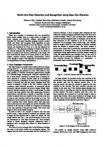
Figure 10 shows the experimental result of the proposed face detection system. The white squares present the detected face on the images. It shows that the face can be detected successfully.
Table 5. Performance of proposed face detection system with 640×480 resolution images
5. CONCLUSION
# of Faces
We present a hardware architecture for face detection based on the AdaBoost algorithm using Haar features. In our architecture, the scaling image technique is used instead of the scaling sub-window, and the integral image window is generated instead of the integral image contains whole image during one clock cycle. The Haar classifier is designed using a pipelined scheme, and the triple classifier which three single classifiers processed in parallel is adopted to accelerate the processing speed of the face detection system. Also we discussed the optimization of the proposed architecture which can be scalable for configurable devices with variable resources. Finally, the proposed architecture is implemented on a Virtex-5 FPGA and its performance is measured and compared with an equivalent software implementation. We show about 35 times increase of system performance over the equivalent software implementation. We plan to implement more classifiers to improve our design. When the proposed face detection system is used in a system which requires face detection, only a small percentage of the system resources are allocated for face detection. The remainder of the resources can be assigned to preprocessing stage or to high level tasks such as recognition and reasoning. We have demonstrated that this face detection, combined with other technologies, can produce effective and powerful applications.
Hardware
1 6 11
Software Classifier 2,165 ms (0.46 fps) 2,919 ms (0.34 fps) 3,129 ms (0.31 fps)
Single Classifier
Triple Classifier
189.199 ms (5.28 fps) 254.254 ms (3.93 fps) 260.169 ms (3.84 fps)
133.143 ms (7.51 fps) 146.745 ms (6.81 fps) 152.664 ms (6.55 fps)
6. REFERENCES [1] Z. Guo, H. Liu, Q. Wang, and J. Yang, “A Fast Algorithm of Face Detection for Driver Monitoring,” In Proceedings of the Sixth International Conference on Intelligent Systems Design and Applications, vol.2, pp.267 - 271, 2006. [2] M. Yang, N. Ahuja, “Face Detection and Gesture Recognition for Human-Computer Interaction,” The International Series in Video Computing , vol.1, Springer, 2001. [3] Z. Zhang, G. Potamianos, M. Liu, T. Huang, “Robust MultiView Multi-Camera Face Detection inside Smart Rooms Using Spatio-Temporal Dynamic Programming,” International Conference on Automatic Face and Gesture Recognition, pp.407-412, 2006. [4] W. Yun; D. Kim; H. Yoon, “Fast Group Verification System for Intelligent Robot Service,” IEEE Transactions on Consumer Electronics, vol.53, no.4, pp.1731-1735, Nov. 2007.
Figure 10. Experimental result of face detection system. [5] V. Ayala-Ramirez, R. E. Sanchez-Yanez and F. J. Montecillo-Puente “On the Application of Robotic Vision Methods to Biomedical Image Analysis,” IFMBE Proceedings of Latin American Congress on Biomedical Engineering, pp.1160-1162, 2007. [6] P. Viola and M. Jones, “Robust real-time object detection,” International Journal of Computer Vision, 57(2), 137-154, 2004. [7] Y. Freund and R. E. Schapire, “A Decision-Theoretic Generaliztion of On-Line Learning and an Application to Boosting,” Journal of Computer and System Sciences, no. 55, pp. 119-139, 1997.
[8] T. Theocharides, N. Vijaykrishnam, and M. J. Irwin, “A parallel architecture for hardware face detection,” In Proceedings of IEEE Computer Society Annual Symposium Emerging VLSI Technologies and Architectures, pp. 452453, 2006. [9] R. McCready “Real-time face detection on a configurable hardware system,” In Proceedings of the Roadmap to Reconfigurable Computing, International Workshop on Field-Programmable Logic and Applications, pp.157-162, 2000. [10] M. S. Sadri, N. Shams, M. Rahmaty, I. Hosseini, R. Changiz, S. Mortazavian, S. Kheradmand, and R. Jafari, “An FPGA Based Fast Face Detector,” In Global Signal Processing Expo and Conference, 2004. [11] Y. Wei, X. Bing, and C. Chareonsak, “FPGA implementation of AdaBoost algorithm for detection of face biometrics,” In Proceedings of IEEE International Workshop Biomedical Circuits and Systems, page S1, 2004. [12] M. Yang, Y. Wu, J. Crenshaw, B. Augustine, and R. Mareachen, “Face detection for automatic exposure control in handheld camera,” In Proceedings of IEEE international Conference on Computer Vision System, pp.17, 206.
[13] V. Nair, P. Laprise, and J. Clark, “An FPGA-based people detection system,” EURASIP Journal of Applied Signal Processing, 2005(7), pp. 1047-1061, 2005. [14] C. Gao and S. Lu, “Novel FPGA based Haar classifier face detection algorithm acceleration,” In Proceedings of International Conference on Field Programmable Logic and Applications, 2008. [15] M. Hiromoto, K. Nakahara, H. Sugano, “A specialized processor suitable for AdaBoost-based detection with Haarlike features,” In Proceedings of IEEE Conference on Computer Vision and Pattern Recognition, pp.1-8, 2007. [16] G. Bradski and A. Kaehler, “Learning OpenCV: Computer Vision with the OpenCV Library,” O'Reilly Media, Inc., 2008. [17] Open Couter Vision Library, , Oct. 2008. DOI=http://sourceforge.net/projects/opencvlibray/ [18] Xilinx Inc., “Virtex-4 Data Sheets: Virtex-4 Family Overview,” Sep. 2008. DOI= http://www.xilinx.com/ [19] J. I. Woodfill, G. Gordon, R. Buck, “Tyzx DeepSea High Speed Stereo Vision System,” In Proceedings of the Conference on Computer Vision and Pattern Recognition Workshop, pp.41-45, 2004.