International Journal of Computing and Network Technology ISSN (2210-1519)
Int. J. Com. Net. Tech. 3, No. 2 (May 2015)
FPGA-Based MWD for Network Error Correction Wael M. El-Medany Computer Engineering Department, College of Information Technology, University Of Bahrain, 32038 Bahrain, Received: 15 Jan. 2015, Revised: 16 April 2015, Accepted: 20 April 2015, Published: (1 May) 2015 Abstract: This paper presents reconfigurable hardware architecture for MWD (Minimum Weight Decoding) algorithm for network error correction, with high throughput on Field Programmable Gate Array (FPGA). Network Error Correction (NEC) is used for detecting and correcting the errors in noisy communication channels when multicasting a source message to a set of nodes. Minimum Weight Decoding (MWD) algorithm is a cyclic linear block codes that are used as Forward Error Correcting (FEC) codes. The design can be reconfigured for different message length and different generator number, the encoder and decoder has been described using VHDL (VHSIC Hardware Description Language). The decoder has the ability to detect and correct different types and different numbers of errors based on the message length and the length of redundant data. The design has been simulated and tested using ModelSim PE student edition 10.4. Spartan 3 FPGA starter kit from Xilinx has been used for implementing and testing the design in a hardware level. Keywords: FPGA; MWD; VHDL; Embedded Networks
1. INTRODUCTION Error Correcting Code (ECC) is a technique used to increase link reliability and to lower the required transmitted power. A detailed description of Error Correcting Code have been given by Egner, 2011; Etzion and Vardy, 2011; Frigo and Stewart, 2014; Huffman and Pless, 2003; Islam, 2010; MorelosZaragoza, 2006; Naseer and Draper, 2008a, ECC enables reconstruction of the original data at the receiving end of the communication channel [1-7]. In (Chang et al., 2010) the main role of Forward Error Correction (FEC) is given, it plays the main role for correcting errors in computer networks, particularly when poor Signal to Noise Ratio (SNR) environments are encountered [8]. In FEC the encoder adds redundant information that allows the receiver to detect and possibly estimate the error location, and hence correct the detected error, for that reason FEC is a suitable ECC technique when single source is broadcasting data to many destinations, as it does not require handshaking between sender and receiver. The concept of Network Error Correction (NEC) codes has been introduced by Cai and Yeung, 2002, 2006; Zhang, 2008, 2011, as a generalization of classical error correction codes, especially when a
source message is transmitted to a set of receiving nodes on a network [9-12]. Minimum weight decoding algorithm is a cyclic linear block coding technique that has the ability of detecting and correcting channel errors in an efficient and reliable manner, the hardware of MWD algorithm has been described by El-Medany et al., 1998; ElMedany et al., 2001, the algorithm has been discussed by Martin et al., 1995; Naseer and Draper, 2008a, b; Peters, 2010; Vardy, 1997, it is a modified version of a well-known error trapping technique that use cyclic shifting for trapping the error [3, 13-18]. In this paper we are introducing the idea of using the well-known MWD decoding technique with reconfigurable architecture in error detection and correction for noisy communication channels in computer networks. The materials in this paper are organized as follows: after this introduction section, a brief discussion about error correcting codes is given in section 2; in section 3, a parity-check encoding and decoding techniques are summarized; the syndrome linear block decoding technique is discussed in section 4; in section 5 we are discussing the VHDL design flow for both ASIC and FPGA designs; reconfigurable architecture is given in section 6; section 7 discuss the
E-mail address:
[email protected]
http://journals.uob.edu.bh
60
Wael Elmedany: FPGA-Based MWD for Network Error Correction
hardware implementation and RTL design; simulation results are discussed in section 8; and finally the conclusion is given in section 9. Wael Elmedany: FPGA-Based MWD …
sequence of k-bits is going to be transmitted over a noisy channel; the transmitter must add some redundant bits or information based on some rules to help the receiver for detecting and possibly correcting the introduced error, this redundant information is the r check digits, it provide the receiver with sufficient information to enable it to detect and correct the channel errors, the length of the transmitted block will be (n = k + r). This issue is called the encoding problem; the message and the added information is called the codeword,it is any particular sequence of n digits that the encoder might transmit. There are 2k codewords available to be transmitted; this set of 2k codewords of length n is called the code [23, 24].
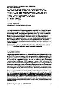
2. ERROR-CORRECTING CODES Error-correcting codes are types of error control coding techniques that are used a noisy communication channel to detect and correct errors at the receiving end in case of forward error correction, they have been described by Bruen and Forcinito, 2011; Huffman and Pless, 2003; Peterson and Weldon, 1972, [7, 19, 20]. The channel may be a high frequency radio link, a Public Telephone Network (PTN), or a Global System for Mobile communication (GSM) network [21, 22]. For example, if a stream of binary data (zeros and ones) is going to be sent through a noisy channel as quickly and as reliably as possible. The error could be due to thermal noise, faults in electronic equipment, human errors, or lightning, etc. Fig. 1 shows an example of a simple error-correcting code, in the form of a binary repetition code. Here the encoder is repeating the message symbol seven times. The other r = 6 bits are repetitions of the message digit. If there is one error that has occurred, the decoder will decode the received vector 1110111 as the "nearest" codeword that is 1111111 or No which is still correct. 3. PARITY-CHECK DECODING
ENCODING
4. SYNDROME DECODING Syndrome decoding is an efficient linear block code that allows decoding of the received codeword over a noisy channel; it is a minimum distance decoding. Assume that a code is a linear block code with (n) code length and minimum distance (dmin), the number of detected errors is given by: ⌊
Where is the number of errors that can be detected, the capability of correcting errors is clearly given by:
AND
⌊
Message Yes or No
0/1
1111111
Encoder Yes= 0000000 No= 1111111
⌋
Where is number of errors that can be corrected. The implemented coding architecture is based on syndrom decoding that can trap the error, and then correct the error in the fly based on the redundant information provided by the parity-check equations [25, 26].
For free error transmission in a digital communication channel, the transmitted binary one will be received as a one, and transmitted zero will be received as a zero. When an error occurs, in a noisy channel, transmitted zero will be received as a one, and transmitted one will be received as zero. Such errors cannot be prevented; but can be reduced by coding techniques. Assume that a message of particular
Yes
⌋
Noise
Noisy Channel 0001000
1110111
Yes
Decoder 1110111 => 1111111
User
Figure 1. Block Diagram for Error Correcting Codes
http://journals.uob.edu.bh
Int. J. Com. Net. Teach. 3, No. 2, 59-68 (May 2015)
16
5. FPGA/ASIC DESIGN PROCESS USING VHDL Application Specific Integrated Circuit (ASIC) and Field Programmable Gate Array (FPGA) are both customized chips that are used for particular applications; there are some advantages and disadvantages for each one of them, but in general FPGA becomes more attractive for its cost effective compared to ASIC especially for low volume of production.
VHDL is a powerful hardware description language that allows complex design concepts to be expressed in a form similar to a computer program. It also allows the complex electronic circuits to be described in behavioral or structural modeling for circuit synthesis purposes or simulation purposes. Fig. 2 shows an overview of the VHDL synthesis process. VHDL source code can be used as the input to a simulator, allowing it to be functionally verified, or it can be passed to synthesis tools for implementation in a specified type of device. Fig. 3 shows simplified diagram for the VHDL design flow of the ASIC/FPGA design process. The flow diagram in Fig. 3 is a simplified one, some other diagrams it show the different levels of implementation for each one of the two target technologies (ASIC/FPGA) [27, 28]. The main differences between them is that FPGA does not require to reach the transistor level, in FPGA the implementation ends by generating a binary file (bit file) that will be used for FPGA configuration .
VHDL Source Files
Synthesis
Functional Simulation
Device Mapping
Timing Simulation
Target Technology FPGA/ASICs
Figure 3. VHDL Design Flow
6. RECONFIGURABLE ARCHITECTURE
Figure 2. VHDL Synthesis Process
Reconfigurable architecture is the ability of rapidly changing to achieve different functionalities of their components and the interconnection between them to a customized design. There most commercially available reconfigurable platform is the Field Programmable Gate Arrays (FPGAs). The main difference with the hardwired ASICs (Application Specific Integrated Circuits) is the possibility of loading a modified circuit of the design on the reconfigurable chip; on the other hand reconfigurable architecture has an advantage of rapid prototyping compared to ASICs that takes more time for long fabrication processing steps. The advantage of FPGA implementation compared to ASIC for the packet FEC architecture is that the design has a reconfigurable minimum distance according to the code length and generator polynomial with different message length as well.
http://journals.uob.edu.bh
62
Wael Elmedany: FPGA-Based MWD for Network Error Correction
7. HARWARE IMPLEMENTATION REGISTER TRANSFER LOGIC DESIGN
AND
The MWD74 design has been synthesized and implemented on Xilinx FPGA chip. FPGAs solve the design challenges in most high-volume, cost-sensitive, I/O-intensive electronic applications. The Spartan-3AN FPGA family was the first Xilinx FPGA family that are RAM based with nonvolatile technology across a broad with different ranges of densities. The family the same features of the Spartan-3A FPGA family in addition to that it has a leading technology in-system flash memory for configuration and nonvolatile data storage. The synthesis process produces the Register Transfer Level (RTL), which is graphical representation of the HDL design module. The RTL produced by Xilinx Synthesis Technology (XST)) is generated by the synthesis tool. The goal of the RTL schematic view is to be as close as possible to the original VHDL code program. In the RTL schematic view, the design is represented in terms of basic building blocks, such as registers, multipliers, and adders. Register Transfer Logic is a high level representation of the digital circuit that is normally generated from a synthesizable VHDL code program. The RTL abstraction generates a set of control signals that initiate the sequence of micro-operations in order to perform specific function. Register transfer logic is a design abstraction that models the sequential circuits in terms of the flow of control signals between the generated memory registers. In general the sequential circuits consist of memory element (registers) and combinational circuit. The combinational circuit consists of logic gates that can perform the logical functions in the digital circuit. The registers synchronize the circuit's operation to the edges of the clock signal, and it is normally implemented as D flip-flops, and this is the memory part of the sequential circuit. In the latest version of Xilinx tools, there is another type of logic level representation, the technology schematic, which is normally based on using different types of Xilinx building block, most of them are Luck-Up Table (LUT). Fig. 4 shows the technology schematic for MWD74 Unit. Fig. 5 shows LUT4_8ACF, which is one of the main building blocks that are shown in Fig. 4. In Fig. 6 the technology schematic for STOP Unit is shown. Fig. 7 and 8 show the RTL Schematic for MWD74 and STOP Units respectively. An example of RTL_mux_7 is given in Fig. 9.
Figure 4. Technology Schematic for MWD74 Unit
Figure 5. Xilinx LUT4_8ACF
http://journals.uob.edu.bh
Int. J. Com. Net. Teach. 3, No. 2, 59-68 (May 2015)
Figure 6. Technology Schematic for STOP Unit
16
Figure 7. RTL Schematic for MWD74 Unit
Figure 8. RTL Schematic for STOP Unit
http://journals.uob.edu.bh
64
Wael Elmedany: FPGA-Based MWD for Network Error Correction
Figure 9. Example of RTL_mux_7
8. SIMULATION CONSUMPTION
RESULTS
AND
POWER
The design has been tested in simulation level and hardware level, the Simulation Results for MWD74 Unit is given in Fig. 10, the waveform in Fig. 10 has been generated using ISim simulator of Xilinx ISE 14.7, it has been tested also using ModelSim PE student edition 10.4. The design has an active low asynchronous reset, and active high input enable. The generator number is 4-bit within the 7-bit gx_p signal; with the 3 MSBs are zeros. The signal cw_p represents the received word that may contain an error. Fig. 11 shows a summary of power consumption, there are three different values that are given in Fig 11, the estimated value, the default value, and the calculated value. Fig. 12 shows the PlanAhead Synthesis for MWD Module, the PlanAhead process operates on the top module of the design after the design is synthesized, the design has 24 instances, 20 IO ports, and 103 nets. In Fig. 13, the summary of software version and target device, user Environment, and device usage statistics are given.
The used Operating System (OS) is NT64, the target family is Spartan 3A and Spartan 3AN, the target device is xc3s700an, the target package is fgg484, and the target speed is -4. Fig. 14 shows the summary of I/O Ports for MWD74 Module, it shows the list of inputs and outputs ports for the MWD74 Module, as well as the data width for each signal. The Design Summary for MWD74 is given in Fig. 15, which shows the consumed resources from the target device (Spartan 3AN FPGA - xc3s 700an-4fgg-484). The summary shows the consumed number of 4-inputs LUTs, number of slices, number of slice flip flops, etc. The consumed resources reflects the cost of the circuit design, large number of consumed resources means high cost, and small number of consumed resources means low cost.
http://journals.uob.edu.bh
Int. J. Com. Net. Teach. 3, No. 2, 59-68 (May 2015)
Figure 10.
Figure 11.
Figure 12.
16
Simulation Results for MWD74 Unit
Summary of Power Consumption
PlanAhead Synthesis for MWD Modul
http://journals.uob.edu.bh
66
Wael Elmedany: FPGA-Based MWD for Network Error Correction
Figure 13.
Summary of software version, user Environment, and Device Usage Statistics
Figure 14.
Summary of I/O Ports for MWD74 Modul
http://journals.uob.edu.bh
Int. J. Com. Net. Teach. 3, No. 2, 59-68 (May 2015)
16
[2] T. Etzion and A. Vardy, "Error-correcting codes in projective space," Information Theory, IEEE Transactions on, vol. 57, pp. 1165-1173, 2011. [3] R. Naseer and J. Draper, "DEC ECC design to improve memory reliability in sub-100nm technologies," in Electronics, Circuits and Systems, 2008. ICECS 2008. 15th IEEE International Conference on, 2008, pp. 586-589. [4] M. Frigo and L. C. Stewart, "Error-correcting code," ed: Google Patents, 2014. [5] S. Egner, "Error correcting code," ed: Google Patents, 2011. [6] R. H. Morelos-Zaragoza, The art of error correcting coding: John Wiley & Sons, 2006. [7] W. C. Huffman and V. Pless, Fundamentals of errorcorrecting codes: Cambridge university press, 2003. [8] F. Chang, K. Onohara, and T. Mizuochi, "Forward error correction for 100 G transport networks," Communications Magazine, IEEE, vol. 48, pp. S48-S55, 2010. Figure 15.
9.
Design Summary for MWD74
CONCLUSIONS
FPGA-based MWD design for network error correction has been simulated and implemented with different code length and different generator number using ModelSim and Xilinx tools. The hardware design has been described using VHDL language, the design has been tested in functional simulation level, and then in hardware environment level using Spartan-3A/3AN FPGA Starter Kit Board. The VHDL source code has been edited and synthesized using Xilinx ISE 14.7, and then simulated and tested using ModelSim (VHDL/Verilog) for different error pattern, different code lengths, and different generator number. The results have been analyzed and compared to other software techniques; the hardware performance is much higher than the software performance. The design cost is much more effective compared to similar designs targeting ASIC design. The final design is targeting Xilinx XC3S700AN FPGA. REFERENCES [1] M. R. Islam, "Error correction codes in wireless sensor network: An energy aware approach," International Journal of Computer and Information Engineering, vol. 4, pp. 5964, 2010.
[9] N. Cai and R. W. Yeung, "Network error correction, II: Lower bounds," Communications in Information & Systems, vol. 6, pp. 37-54, 2006. [10] Z. Zhang, "Linear network error correction codes in packet networks," Information Theory, IEEE Transactions on, vol. 54, pp. 209-218, 2008. [11] N. Cai and R. W. Yeung, "Network coding and error correction," in Proc. 2002 IEEE Inform. Theory Workshop, 2002, pp. 119-122. [12] Z. Zhang, "Theory and applications of network error correction coding," Proceedings of the IEEE, vol. 99, pp. 406-420, 2011. [13] I. Martin, B. Honary, and P. Farrell, "Modified minimumweight decoding for Reed-Solomon codes," Electronics Letters, vol. 31, pp. 713-714, 1995. [14] C. Peters, "Information-set decoding for linear codes over F q," in Post-Quantum Cryptography, ed: Springer, 2010, pp. 81-94. [15] R. Naseer and J. Draper, "Parallel double error correcting code design to mitigate multi-bit upsets in SRAMs," in Solid-State Circuits Conference, 2008. ESSCIRC 2008. 34th European, 2008, pp. 222-225. [16] A. Vardy, "The intractability of computing the minimum distance of a code," IEEE Transactions on Information Theory, vol. 43, pp. 1757-1766, 1997. [17] W. El-Medany, C. Harrison, and P. Farrell, "VLSI chip design implementation for minimum weight decoder," in Communication systems & digital signal processing. International symposium, 1998, pp. 490-493.
http://journals.uob.edu.bh
68
Wael Elmedany: FPGA-Based MWD for Network Error Correction
[18] W. El-Medany, C. Harrison, P. Garrell, and C. Hardy, "VHDL implmentation of a BCH minimum weight decoder for double error," in Radio Science Conference, 2001. NRSC 2001. Proceedings of the Eighteenth National, 2001, pp. 361-368.
[24] T. J. Richardson and R. L. Urbanke, "Efficient encoding of low-density parity-check codes," Information Theory, IEEE Transactions on, vol. 47, pp. 638-656, 2001.
[19] A. A. Bruen and M. A. Forcinito, Cryptography, information theory, and error-correction: a handbook for the 21st century vol. 68: John Wiley & Sons, 2011.
[25] J. Stern, "A new identification scheme based on syndrome decoding," in Advances in Cryptology—CRYPTO’93, 1994, pp. 13-21.
[20] W. W. Peterson and E. J. Weldon, Error-correcting codes: MIT press, 1972.
[26] P.-L. Cayrel, P. Véron, and S. M. E. Y. Alaoui, "A zeroknowledge identification scheme based on the q-ary syndrome decoding problem," in Selected Areas in Cryptography, 2011, pp. 171-186.
[21] J. Scourias, Overview of GSM: The global system for mobile communications: University of Waterloo, Computer Science Department, 1996. [22] C. Peersman, S. Cvetkovic, P. Griffiths, and H. Spear, "The global system for mobile communications short message service," Personal Communications, IEEE, vol. 7, pp. 1523, 2000. [23] Z. Li, L. Chen, L. Zeng, S. Lin, and W. H. Fong, "Efficient encoding of quasi-cyclic low-density parity-check codes,"
Communications, IEEE Transactions on, vol. 54, pp. 71-81, 2006.
[27] D. J. Smith and A. Foreword By-Zamfirescu, HDL Chip Design: A practical guide for designing, synthesizing and simulating ASICs and FPGAs using VHDL or Verilog: Doone Publications, 1998. [28] C. Maxfield, The design warrior's guide to FPGAs: devices, tools and flows: Elsevier, 2004.
Wael Mohamed Elmedany holds a PhD degree in Electrical Engineering, Manchester University, UK, 1999; MSc degree in computer communications, Menoufia University, Egypt, 1991; BSc degree in Electronic Engineering, Menoufia University, Egypt 1987. He is the founding and managing editor of International Journal of Computing and Digital Systems (IJCDS). He has been invited as a Guest Editor for Inderscience special issue on International Journal of Embedded Systems entitled “Reconfigurable Architectures and Self-adaptive Autonomic Systems”. He is the organizer and Program Chair of MobiApps 2014, 27-29 August 2014, Barcelona, Spain and DPNoC 2014, August 17-20, 2014, Niagara Falls, Ontario, Canada; he is also Program Chair of RASAS’14, September 24-27, 2014, Delhi, India. El-Medany is also IEEE member. He is a member of editorial boards and technical program committees of many international journals and conferences, reviewer in many international journals and conferences, and acts as chairperson in many conferences. El-Medany has around fourty publications, and attended several national and international conferences and workshops. His research interests in ASIC design, FPGA, embedded systems, remote monitoring systems, and reconfigurable computing.
http://journals.uob.edu.bh