Piotr Rutkowski, Ryszard S.Romaniuk, Krzysztof T.Poźniak, Tomasz JeżyÅski, .... 1 Three layer functional communication model assumed for the system design.
TESLA Report 2003-32
FPGA based TESLA cavity SIMCON DOOCS server design, implementation and application Piotr Rutkowski, Ryszard S.Romaniuk, Krzysztof T.Poźniak, Tomasz Jeżyński, Piotr Pucyk ELHEP Laboratory, Institute of Electronic Systems, Warsaw University of Technology Michał Pietrusiński, Institute of Experimental Physics, Warsaw University Stefan Simrock, DESY, Hamburg ABSTRACT A concise overview of the laboratory solution of the FPGA based TESLA cavity simulator and controller (SIMCON) is presented. The major emphasis is put in this paper on the high level part of the system. There were described the following steps of the system design and realisation: solution choice, design of system components, implementing the solutions, introduction of the application, initial analysis of the working application. The paper is a first description of the working DOOCS server for the FPGA based TESLA cavity SIMCON (which is a part of the LLRF subsystem). The data gathered from the work of the DOOCS server promise for the system optimisation possibilities. The server will be supplemented with the GUI in the next step of this effort. Throughout the work we will refer to the debated system as to the TESLA SIMCON DOOCS server or in short the “simcon server”. The hardware layer of the TESLA cavity SIMCON (to which the designed software refers to) was realized in a single FPGA Virtex chip by Xilinx (XC2V3000 development board by Nallatech). Keywords: TESLA, Free Electron Laser, X-Ray FEL, Superconducting cavity control, LLRF system, FPGA, DOOCS, Internal Interface Middleware, virtual hardware control systems, C++,
1. INTRODUCTION The X-FEL facility and TESLA accelerator (TTF II phase), which base on the superconducting technology, is under construction in Deutsches Elektronen Synchrotron in Hamburg. The accelerator is controlled by the Low Level Radio Frequency (LLRF) system. The LLRF consists of the hardware and the software components. The hardware equipment is controlled by the Distributed Objected Oriented Control System (DOOCS) [1]. In general, the DOOCS is expected to control all the hardware components in the X-FEL facility and TESLA experiment. Since 2002 the ELHEP Group [2] is attempting to build a part of the new generation of the LLRF systems for TESLA basing on the FPGA technology. These attempts base on the previous positive experiences of the Group to introduce the FPGA solutions in the large, distributed, measurement, control and diagnostic systems for the ZEUS and CMS experiments [3]. This work presents a next attempt in this direction to build a part of the DOOCS system destined to operate with the TESLA FPGA based cavity controller and simulator. Precisely, this work is a presentation of the software development for the FPGA based TESLA cavity SIMCON DOOCS server in respect to the existing environment and the hardware base developed so far at DESY. The article tries to describe in a systematic way the current stage of the work from a big picture to the details. The work consists of the following parts: 1- system overview, 2- hardware-software environment, 3- DOOCS sever description, and 4- initial tests of the server properties. In the first part of the paper, the general idea of the work is presented in the form of the overall system overview. Three major communication layers of the system were presented: starting from the access to the hardware functionalities, through the intermediate (middleware) communication with hardware to the control of the hardware parameters. The aims and advantages of such a three layer approach were debated. The properties of the middleware communication system with the hardware was described in the previous
TESLA Report [4]. The second part describes some relevant aspects of the hardware-software environment in which the designed system is expected to work. Especially the interactions between the two essential system layers are emphasized. The third part debates the process of DOOCS server design, implementation and application. There are described the used tools, class specification, programming specifics, server properties. The fourth part presents the results of initial tests of the server properties and its interaction with the SIMCON hardware. The hardware and software dependencies get more and more complicated with the advent of the new generations of the FPGA technology (equipped with DSP capabilities) [9]. The software is able to penetrate deeply into the electronics structure shaping more precisely its functionalities. This paper shows also this tendency, as the applied FPGA chip has a number of DSP blocks. The work concludes with some indications concerning the future directions of research. These directions include: control of multichannel SIMCON [4] hardware, running of the full plant simulation, system exception handling, serving the system via an intelligent GUI over the DOOCS and the WWW, etc.
2. OVERVIEW OF FPGA BASED TESLA CAVITY SIMCON SYSTEM SERVED BY THE DOOCS Throughout this work, a specific kind of the systematic approach was introduced for the design process of the software layer for the TESLA cavity SIMCON system (a part of the LLRF) [4,7]. The aim of this approach is to keep the software to reflect the hardware functionality as much consistent as possible. Three layers communication model has been applied in the design of the whole TESLA cavity control system (Fig.1). • On the top, there is a high level software layer that interacts indirectly with the hardware functionalities. • The second layer is a special, middleware type, communication interface enabling the hardware access via a welldefined and efficient mechanism [3]. The mechanism gives very precise access to the hardware BIOS with the accuracy to a single bit. This layer may also be called a virtual hardware one. The suggested name for this layer is Internal Interface [4]. • The lowest level is occupied by the physical hardware with the expected functionality implemented in particular chips, circuits, devices, boards, racks, etc. HIGH LEVEL SOFTWARE object oriented - C++
COMMUNICATION II (Internal Interface) hardware access interface
FUNCTIONALITY algorithms fitted into hardware
Due to the standardization and high efficiency of the Internal Interface [4], the hardware design is more efficient and well coordinated with the control software layer, which is driving the physical hardware equipment. The designed software can be implemented in different hardware and communications environments and for a variety of application purposes, not only in the LLRF system. The DOOCS server, which is controlling the FPGA chip, is situated in the top layer of the system design. It creates the high level software of the system. There are some initial a priori conditions for the system design. The DOOCS server for the TESLA cavity controller must be well coordinated with the existing DOOCS infrastructure. This infrastructure includes Solaris operating system, recent DOOCS libraries (updated by CVS) and DOOCS C++ classes methodology (DOOCS native classes are the core that the developer will inherit his classes from). Fig. 1 Three layer functional communication model assumed for the system design of the TESLA cavity controller and simulation (SIMCON) served by the DOOCS. The whole control system is composed of the graphical user’s interface (GUI), the server, the communication and virtual hardware, and the physical hardware realized in FPGA.
The other design requirements are as follows. The designed server is required to be flexible for the future development and upgrades. Frequent upgrades will definitely occur during the preliminary stage of its development, before the FPGA based TESLA cavity SIMCON system solution is not yet finished to the commissioning stage and then ready for the industrial exploitation with the X-Ray FEL. These boundary conditions put now the developer in the focal point for the commissioning of the whole system. The DOOCS server, via the GUI (DOOCS and WWW), is a final product
combining all hardware functionality for the end-users, which are: experiment operators, scientists, service engineers and other clients of the system parts (humans and machines) i.e. FSM [4] etc. Fig. 2 presents the three layer model of the hardware-software interaction in the system under design. It is a logical extension of the basic model presented in fig.1. In the assumed design approach, each layer is separated from another by internal middleware layers. This picture presents the design approach by illustrating it with a particular example. The example shows a method to change the value of a particular physical hardware register from the level of the Graphical User Interface. The full path is shown form the system operator to the level of the hardware. The left panel of fig.2 shows the functional blocks and particular functionalities used by the system, while the right panel shows transition of the software layer from the C++ code of the GUI, through C/C++ of the Internal Interface to the VHDL code of the virtual and physical hardware [4]. GUI
C++
Control, monitor, diagnose applications. Based on system application and environment specifics Core - II access library Low level hardware access (based on Internal Interface) USB, LPT, Ethernet ...
Internal Interface (II) Core - hardware independent Registry, memory accessing
Write(”A12",”0xfff”)
WriteII(0x000B,14,0xff)
C/C++
VHDL Write
VHDL
Hardware Input/Output Specific hardware application
A12 = 0xfff Register - name: A12
Fig. 2 Three layer implementation example of the FPGA based TESLA cavity SIMCON served by the DOOCS. The aim of the DOOCS server for the FPGA based TESLA cavity controller and simulator is to:
a) provide DOOCS users with the access to the hardware (registers, memory), b) control hardware with respect to the requested and implemented algorithms. In order to achieve these aims, one must be equipped with the possibility to access efficiently the hardware. Here, the efficiency means speed and accuracy. Thus, the precise software interface to the physical hardware layer must be crated. This interface should be flexible enough to deliver the access to all of the FPGA chips in the system via a few different paths. Theses paths include (among others) the intermediate Windows server and the communication links over the USB or LPT [5]. The flexibility means also that changing of the access method to the hardware from one to the other should have practically no impact on the inner logic of the server. In order to meet this requirement the server must be designed in the standardized Objected Oriented Programming (OOP) style. The SIMCON DOOCS server under consideration was designed in the OOP way, which gives the following advantages: a) Using the interface classes separates the users from the implementation specifics, b) Server development is easier – the objects and their relations are easy to see and understand, c) Debugging and bug fixing is faster because the system developer knows better what the C++ code does, d) The understanding of the project by the team members can be much better, because the diagrams are used as well as the common description language like UML is used.
The first version of the FPGA based TESLA SIMCON DOOCS server classes has been created. One should be able to crate the server fitted to the exact needs of the user and equipped with the users’ control algorithm. The implemented hardware interface has an access via the intermediate Windows server. The possibility to work over the direct access via the LPT link from the Solaris environment is investigated and should bring the results soon.
3. HARDWARE-SOFTWARE SYSTEM ENVIRONMENT FOR FPGA BASED TESLA CAVITY SIMCON SERVED BY THE DOOCS The following section presents an overview of the SIMCON server system architecture. The architectural ideas were realized and checked in operation in the real test environment. The software and hardware layers were checked separately, as well as the interaction between them. In the end, the both layers create a unified and effectively working environment. Hardware Software
VME crate
USB
FPGA
Hardware logic
LPT
LPT
LPT USB
SUN
DOOCS server
PC
Windows Application
Software communication path from the DOOCS server to the hardware via the Windows server Software communication path from the DOOCS server to the hardware directly from SUN Hardware communication path between system elements
Fig. 3 System overview of the FPGA based TESLA cavity SIMCON integrated with the dedicated DOOCS server. The signal paths between various system blocks are indicated via different I/O ports.
The SIMCON DOOCS system under debate consist of two essential layers: the hardware and the software: The hardware layer includes the following components: 1. VME crate situated in the Linac Hall, 2. FPGA development board (in the VME crate), 3. SUN – SunOS 5.8 (in the VME crate), 4. PC – Windows 2000, near the VME crate. The software layer has the following components: 1. The DOOCS server (on the SUN), 2. Intermediate Windows Application with TCP/IP server (on the PC). The system operation can be divided into two phases: 1. Accessing the hardware register via the intermediate Windows server (using the TCP communication protocol), 2. Accessing of the FPGA registers directly from the Solaris environment (using LPT communication interface) [4]. The data paths of these two operations phases were designated with the following abbreviation TCP and LPT respectively, and presented schematically in fig.3. Xilinx FPGA
USB
LPT
DAC Fig. 4 A photograph of the VME board used to construct the FPGA based TESLA cavity SIMCON system. Location of the key components of the system were indicated.
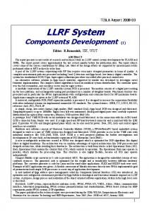
Fig. 4 presents the FPGA board used in the experiments with the TESLA cavity SIMCON. The development board with the Virtex chip was mounted on a specially designed VME carrier board, fitting the classical VME crate. The board is designed to work in the standard rack, near the accelerator. The major system functionality of the TESLA cavity SIMCON is placed in the FPGA chip with the VHDL code. The board has the all I/O ports necessary for realization of the SIMCON function. These I/O ports are: USB, LPT and DAC/ADC. The DOOCS has intermediate access to these ports and to the FPGA (and other functionalities of the board) via these I/O ports.
4. OPERATION DESCRIPTION OF SIMCON DOOCS SYSTEM According to the block diagram and signal paths presented in fig.3, there are two separate communication protocols used by the system, the TCP and LPT. The TCP protocol based phase of the system operation can be described by the following individual activities (steps): Booting – The booting of the SIMCON system is performed via the USB link from the PC upon the operator’s request. This starts all the other processes. The DOOCS server is exchanging data with the FPGA chip. Read – The Doocs property on the SUN DOOCS server calls the application on the PC machine for the read process of the relevant register value. The Windows application translates this call to the commands accessing the FPGA and retrieving the data. The PC sends this data to the SUN. The DOOCS server converts the hardware hex value to the float value, within the expected range. Write – The Doocs property on the SUN DOOCS server converts the float value to the hardware hex value and calls the Windows application on the PC for the writing process to the proper register. The application translates this call to the commands accessing the FPGA chip and writing data. To verify the process, the PC retrieves the data from the register and sends the data back to the SUN. The DOOCS server checks the difference between the write and read values and the logics (which is embedded in the server) reacts accordingly to the user expectations (i.e. server shutdown or just writing the fact to the log file). The LPT protocol based phase of the system activities can be described by the following individual activities (steps): Booting – The booting is performed via the USB link from the PC1 machine upon the operator’s request. This starts all the other processes. During this phase, the data is being exchanged between the DOOCS and the FPGA chip. Read – The Doocs property on the SUN DOOCS server calls a method responsible for the read of the relevant register value. Within this method, the commands accessing the FPGA and retrieving the data are executed. The conversion of the hardware hex value to the floatvalue, within expected range is performed at the end of this operational step. Write – The Doocs property on the SUN DOOCS server calls the method responsible for the write process to the relevant register value. Within this method, the commands accessing the FPGA chip like writing, retrieving, and verifying the data are executed. The conversion of the hardware hex value to the float value within the expected range is performed at the end of this step of the process.
5. TESLA CAVITY SIMCON DOOCS SERVER – SOFTWARE DESCRIPTION The software for TESLA cavity SIMCON DOOCS server was written in C++. Fig. 5 presents the SIMCON system overview. The DOOCS client can access the FPGA chip hardware via the special classes (inherited from the DOOCS native D classes). These classes access the FPGA chip hardware by the TCP/IP communication protocol with the Windows application. The Windows application communicates with the FPGA via the LPT interface. The TCP/IP communication layer protocol is hidden in the classes implementing the hardware access interface. The provided D FPGA classes offer the log mechanism to the log file. Any unexpected, strange behaviour of the SIMCON DOOCS server may be easily reported to the user. The basic exceptions, which are handled, are reported to the log file automatically. The server is supposed to provide the end-user, having access to the system via the DOOCS client, with the access to the expected FPGA registers and the memory by more than a single path (i.e. via the TCP/IP or the LPT I/Os) but also in the transparent manner for the DOOCS client. It means, that from the clients’ point of view, there is no difference
1
Nallatech (manufacturer of the used development board with Xilinx chip) doesn’t provide currently drivers for the Solaris environment. – In the future, other method will be implemented. One of them is to use proprietary protocol and to boot the FPGA directly from the SUN. However, the method may be difficult and have confined universality. That is why this paper doesn’t include this as an option. This option needs further investigation.
between the underlying FPGA communication mode implementations. However, there can be a difference in the performance. The write/read process time may differ for each of the communication methods. 5.1 Communication overview of the string TCP/IP based protocol The communication between the D FPGA classes and the Windows application is implemented by the string commands and exchange of the mutual responses. There is a set of commands that Windows server understands and can respond to, in a well-defined way. The client connected to the Windows server may request writing, reading to the FPGA registers and to the memory. Other commands, based on the users’ needs are (or easily can be) provided. SOLARIS DOOCS ELHEP se rver
TCP/IP
T fpga_tcp (im plem ents Ifpga_access)
W INDOW S
T fpga_lpt (im plem ents Ifpga_access) Appl ication, T CP/IP server
D_spectrum _fpga (inherited from D_spectrum )
D_nam e_fpga (inherited from D_nam e)
D_float_fpga (inherited from D_float)
LPT link LPT
fpga_server.log
Vi rtex board
DOOCS cli ent
Fig. 5 FPGA based TESLA cavity SIMCON DOOCS System - C++ overview. Two OS cooperate with the TCP/IP application server residing on the MSW. The SIMCON board (with Virtex) has access to the MSW OS via the LPT link. The SIMCON DOOCS server, residing in SOLARIS OS communicates with the SIMNCON board via the LPT link.
The description of the commands exchanging mechanism between all components of the system under design (Fig. 6) is as follows: • The client application sends the request to the Windows application, with the TCP/IP server running. • The server receives the string command, parses it to get the information which one of the FPGA registers to read or to write.
• •
The Windows application accesses the expected hardware register and performs the read or write operation. According to the result of the operations, during the above steps, the return string is prepared and is sent back to the client application. This ends the exchange mechanism protocol.
text strings
DOOCS 1
...
2
C++ Aplication 4
"#A22 11 $"
LPT
Matlab
"#S A22 11 #G A22 #RUN $"
TCP/IP connection 3
FPGA
Fig. 6 The string communication mechanism between the Windows application and all of its possible clients in the FPGA based TESLA cavity SIMCON DOOCS server under design.
The string exchange method of communication has its clear advantages and disadvantages. The main disadvantage in the string communication method is the large amount of data that needs to be transferred via the TCP/IP link. The need of transmission of the binary messages could reduce the amount of the data. On the other hand, a simple method string exchange makes it feasible to connect the different applications to the Windows server, which is directly commanding over the FPGA hardware. In this project, this feature was broadly applied [6][7]. The second reason for application of string communications was the fact that intermediate Windows server is a temporary solution, in comparison to the direct communication between the DOOCS and the FPGA via the LPT port and link. The crucial factor for making the operation with the FPGA from the DOOCS possible via the LPT was tight time schedule of the system application. Further work is carried to use other ports and protocols for the purposes of the internal system communications. 5.2 Overview of the DOOCS server classes for the TESLA cavity SIMCON system The (FPGA based TESLA cavity) SIMCON DOOCS classes design diagram is presented in the Fig. 7. To make the diagram more comprehensible the following presentation colours were applied: • D classes are filled with the blue colour. • Interface classes are filled with the green colour. • Exception classes are filled with the orange colour.
Fig. 7 Class diagram showing all interdependencies between the TESLA cavity SIMCON DOOCS classes.
6. CLASSES DETAIL Below, there is a description of the all classes used in the server designed for the FPGA based TESLA cavity SIMCON. The classes are in the alphabetic order with some comments. Some of the descriptions may be trivial, but they are included for the instruction and documentation purposes. The class description include the following items: Class name, inherits from (extends), field summary, comment, and method summary. Class D_float
In order to allow log warnings and exceptional situations this class inherits from Tlog_name also
class D_float DOOCS native D class. It enables writing and reading float value from the DOOCS server Class D_float_fpga D_float | +--D_float_fpga class D_float_fpga Extends: D_float, Tlog_name Extended DOOCS D class with fpga access via the IFpga_acess interface. In order to allow log warnings and exceptional situations this class inherits from Tlog_name also Field Summary Private Fpga_access Ifpga_access private Iu2_str U2_str
Field Summary private Fpga_access Ifpga_access Class D_spectrum class D_spectrum DOOCS native D class. It enables writing and reading table of float values from the DOOCS server Class D_spectrum_fpga D_spectrum | +--D_spectrum_fpga class D_spectrum_fpga Extends: D_spectrum, Tlog_name Extended DOOCS D class with fpga access via the IFpga_acess interface. In order to allow log warnings and exceptional situations this class inherits from Tlog_name also
Class D_name class D_name DOOCS native D class. It enables writing and reading char* value from the DOOCS server Class D_name_fpga D_name | +--D_name_fpga
Field Summary private Ifpga_access Fpga_access private Iu2_str Iu2_str
Method Summary public fill_spectrum_buf(Tbuf_values ) void Additional method to basic D_spectrum methods' set. Gets values from the fpga hardware and writes to D_class spectrum storage
class D_name_fpga Extends: D_name, Tlog_name Extended DOOCS D class with fpga access via the IFpga_acess interface.
Class Efpga class Efpga
Exception class. Exceptions generated by the classes implementing Ifpga_access. Class Efpga_diff Efpga | +--Efpga_diff
Class Emat class Emat Exception class. Mathematical convertion operation exception. Example - value exceeds defined maximal range Class Ifpga_access abstract class Ifpga_access
class Efpga_diff Extends: Efpga Message - "requested value different from returned" Class Efpga_empty Efpga | +--Efpga_empty class Efpga_empty Extends: Efpga Message - "no data retrieved from the server" Class Efpga_srv Efpga | +--Efpga_srv class Efpga_srv Extends: Efpga Message from the server - "unknown server error" Class Efpga_wait Efpga | +--Efpga_wait class Efpga_wait Extends: Efpga Message from the server - "waiting for the data"
Interface class to the fpga hardware. It enables all methods required to access fpga registers and memory. Interface has the least method list needed - in order to keep class' methods easily understandable. This interface is expected to be implemented as: 1. TCP/IP intermediate Windows server. 2. LPT interface 3. Ethernet (connection from SUN to PCs on llrf board) Interface should report abnormal operation as exception from well defined set of exceptions - derived from E_fpga Method Summary public abstract BootFile(std::string ) void Possibility of booting fpga with specified field name public abstract Read() std::string Reading value from fpga register public abstract ReadBuf() Tbuf_values Reading values from fpga buffer/memory. Tbuf_values is a user defined type - collection of strings. public abstract Write(std::string ) void Writing value to fpga register public abstract WriteBuf(Tbuf_values ) void Writing values to fpga buffer/memory. Tbuf_values is a user defined type - collection of strings. public abstract WriteRd(std::string ) std::string Writing and Reading value to fpga register. In one method full readwrite path is executed. Data validation should be performed and in case of difference between written and read values than proper exception should be thrown (Efpga_diff)
Class Iu2_str abstract class Iu2_str Convertion between float value and hex value (in u2 code) in string form. This convertion is needed by the hardware
access interface - Ifpga_interface communicates with underlaying fpga in hex format. Method Summary Method Summary public abstract GetFloat(std::string ) long double public abstract GetString(long double ) std::string Class Tfpga_clnt
protected Recv() std::string protected void Recv0() protected Recvs() Tbuf_values protected void Send(std::string ) Class Tfpga_treg
class Tfpga_clnt TCP/IP connection basic handling (open, close). One object of this class is expected to handle connection for all objects of Tfpga_tcp. Class Tfpga_tbuf Ifpga_access | +--Tfpga_tcp | +--Tfpga_tbuf class Tfpga_tbuf Extends: Tfpga_tcp Full Ifpga_access implementation. Access to memory. Methodes ralated to fpga registers throws exceptions (they are not implemented in this class) Class Tfpga_tcp Ifpga_access | +--Tfpga_tcp class Tfpga_tcp Extends: Ifpga_access First implementation of the Ifpag_access - via the TCP/IP intermediate Windows server. Basic methodes to access fpga. Needs to be inherited from and to implement main Ifpga_access interface methodes. It is not a full interface - it contains workhorse methods for basic operation in TCP/IP communication. Field Summary private Tfpga_clnt Fpga_clnt protected std::string Name
Ifpga_access | +--Tfpga_tcp | +--Tfpga_treg class Tfpga_treg Extends: Tfpga_tcp Full Ifpga_access implementation. Access to hardware register. Methodes ralated to fpga buffers throws exceptions (they are not implemented in this class) Class Tlog_name class Tlog_name Log writnig class. Enable logging to specified file. It automatically adds name and date in each entry written to file Method Summary public void WriteLog() 1.1.1. Class Tu2_str Iu2_str | +--Tu2_str class Tu2_str Extends: Iu2_str Implementation of Iu2_str. Convertion of hex code to float within expected range.
7. CODE EXAMPLE The basic operation of the application with the described classes is presented below. There is shown a process of creating the two objects of classes accessing the FPGA register - named “SI” - and the FPGA memory named “VOUT_I_B”. Table 1. Declaration examples C++ code Comment FILE *log_file_; log file handler Tu2_str* U2_str; float->hex convertion Tfpga_clnt* Fpga_clnt; TCP/IP conn handling Tfpga_treg* Fpga_treg_SI; fpga register access D_name_fpga* Name_fpga_SI; reg access – D class Tfpga_treg* Fpga_treg_SQ; fpga register access D_float_fpga* Float_fpga_SQ; Tu2_str* U2_str_dac; Tfpga_tbuf* Fpga_tbuf_voutI; D_spectrum_fpga* Spectrum_buf;
reg access – D class float->hex convertion fpga memory access memory access – D class
Table 2. Initialisation of variables - examples with comments. C++ code
Comment
if ((log_file_ = fopen("fpga_server.log","a+")) == NULL) { fprintf(stderr,"Cannot open log file fpga_server.log!"); exit(-1); }
opening fpga log file: fpga_server.log
U2_str = new Tu2_str(-1,1,18); Fpga_clnt = new Tfpga_clnt("131.169.149.195",10024);
convertion float -> hex for 18 bits TCP/IP connection handling
Fpga_treg_SI = new Tfpga_treg("SI",Fpga_clnt); Name_fpga_SI = new D_name_fpga("TEST.SI text", dynamic_cast(Fpga_treg_SI), log_file_);
operations to deliver D class for the fpga register
Fpga_treg_SQ = new Tfpga_treg("SQ",Fpga_clnt); Float_fpga_SQ = new D_float_fpga("TEST.SQ float", dynamic_cast(Fpga_treg_SQ), U2_str,log_file_);
operations to deliver D class for the fpga register with float -> hex convertion
U2_str_dac = new Tu2_str(-1,1,14); Fpga_tbuf_voutI = new Tfpga_tbuf("VOUT_I_B",Fpga_clnt,1000); Spectrum_buf = new D_spectrum_fpga("OUT_I buffer", 1000,this,Fpga_tbuf_voutI,U2_str_dac log_file_);
operations to deliver D class for the fpga memory with float -> hex convertion
8. RESULTS
The first versions of the DOOCS servers for the TESLA cavity SIMCON hardware control have been developed. The initial tests of the server properties have been investigated. The VME – FPGA board with the Virtex chip to be controlled via the server contains the full models of the cavity controller and simulator (SIMCON). The controller is in its basic version and single-channel. Both of these functionalities (simulation and control) have to be operated efficiently by the DOOCS server. Below, we describe these features separately and then together. 8.1. DOOCS server for the TESLA cavity Simulator In the Fig. 8 below, the result of the working DOOCS server for the TESLA cavity simulator is presented. The RPC_TEST client application is connected to this server. The server provides the user with the access to the simulator parameters that are embedded in the FPGA registers. One can easily change the desirable cavity simulator parameter within the DOOCS system environment. This is done by the choice of the parameters in the standard DOOCS window.
Access to the fpga registers Manipulation on cavity simulator parameters possible
Parameters of the cavity simulator model Fig. 8 The example of the TESLA cavity simulator DOOCS server.
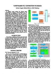
8.2. DOOCS server for the TESLA cavity Controller Fig. 9 visualizes the FPGA readout from one of the chosen buffers. The write and read operations are performed. On the controller output, there is a buffer implemented which can be accessed for the write and read operations. In the first step, after the DOOCS server startup, an exemplary signal envelope is written to the buffer. For the illustration purposes, the shape of the written signal is sine wave. When running, the server updates periodically by the DOOCS property, reflecting the FPGA buffer content.
Fig. 9 The example of the TESLA cavity controller server. The next figure 10 presents the result of DOOCS server operation with the real signal from the real TTF II cavity.
Fig. 10 DOOCS server window for the real signal operation example. 8.3. DOOCS server for the TESLA cavity SIMCON In the Fig. 11 below the result of the TESLA cavity SIMCON is presented. Through the RPC_TEST the user can read and write the SIMCON parameters simultaneously. In a single DOOCS server, the TESLA cavity simulator and controller functionalities are combined.
Cavity simulator parameters. Controller tables (set points, feed forward etc.
Fig. 11 DOOCS server window for the TESLA SIMCON operation example. This server is being tested and is prepared as a main solution for the end user. It gives a great opportunity to work with the bundled simulator-and-controller in the various configurations: only simulator active, only controller active, simulator and controller in the loop. A choice of the number of different loops is possible, what is described in [7].
Fig. 12. The SIMCON window for the readouts presented below in fig. 13.
Fig 13. a) „Fish like” signal before detection (internal parameter - MUX_DAQ4 = 1); b) Cavity output I (MUX_DAQ4 = 3); c) Cavity output Q (MUX_DAQ4 = 4) ; d) Cavity detuning (MUX_DAQ4 = 2).
Fig. 14. MatLab window [10] showing the same signals as presented in the DOOCS server window in fig.13.
9. CONCLUSIONS The first FPGA based TESLA cavity SIMCON DOOCS servers have been created and preliminary test have been accomplished. Basing on this initial experience, a trial to enclose the debated server development in the standardised development procedures of the existing DOOCS environment was successfully demonstrated. A three layer based design approach to the server development and its interaction with the FPGA hardware was assumed. These layers are: high-level software layer, communication layer and hardware layer. This approach provide the system designer with the following advantages: • • • •
Design of each layer is independent from the other (with established interfaces between layers), Task are divided between the experts in each area, Development can be performed for each layer independently, Responsibility for each level development is well defined.
The optimal server design for a complex control system is an iterative and long lasting process. The knowledge and understanding gathered from the first implementation can lead to a continuous process of the software upgrade. The current aim is to enrich the functionalities of the electronics, what has been offered recently by the new series of the FPGA chips, equipped with DSP blocks. The DOOCS control server should keep up with these advances of the electronics and photonics systems. The DOOCS server should also react to the changing needs of the system operators. The DOOCS server should add to the system reliability and ease the system maintenance.
The FPGA based TESLA cavity SIMCON system performance and reliability tests are now being performed. The DOOCS server participates in these tests. The new system functionalities are considered to be added like: multiple cavity control and simulation, cavity parameter identification, exception handling, cavity microphonics control, FSM, etc. The designed DOOCS server works now continuously with the FPGA based TESLA cavity SIMCON and the measurement and behaviour data are gathered. The results will be presented in the next TESLA Report.
10. REFERENCES [1] http://doocs.desy.de [2] http://tesla.desy.de/~elhep [3] Proceedings of SPIE, Bellingham, WA,USA, Vol. 5125, 2003 [www.spie.org] [4] K.T.Poźniak, et. Al., Parameterized control layer of FPGA based TESLA cavity SIMCON, TESLA Report 2003-30; http://tesla.desy.de/new_pages/TESLA_Reports/2003/pdf_files/ [5] http://tesla.desy.de/doocs/doocs_gen/fsm.html [6] http://tesla.desy.de/~elhep/home/prutkows/FPGA_DOOCS.pdf [7] T. Czarski, et. Al., Cavity Digital Control Testing System by Simulink Step Operation Method for TESLA Linear Accelerator and Free Electron Laser, TESLA Report 2003-20 [8] T.Czarski, et. al., Cavity Control System, Advanced Modelling and Simulation for TESLA Linear Accelerator, TESLA Report, 2003-06 [9] K.T. Poźniak, et al., Functional analysis of DSP blocks in FPGA chips for application in TESLA LLRF system, TESLA Report 2003-29 [10] T.Czarski et al., TESLA cavity modelling and digital implementation with FPGA technology solution for control system, TESLA Report 2003-28