Connection to Allow In-System Programming (ISP). • Runs off Portable 9V ...
Programming Specification for Atmel's FPGA Configuration EEPROMs. •. In-
System ...
Features Hardware • • • •
Supports Programming of all AT17LV and AT17F Series Devices Connection to Allow In-System Programming (ISP) Runs off Portable 9V DC Power Supply 5.0V Supply
Software • • • • • • •
CPS – Configurator Programming System GUI-based Interface Supports Windows® 95/98/2000 and WindowsNT® Online Help Supports Programming Reset Polarity Verification Routines to Validate Programming Accepts HEX, MCS, POF, RBF and BST File Formats
FPGA Configurator Programming Kit (Enhanced)
System Contents • • • • • • • • •
ATDH2200 Programming Board ATDH2222 20-pin PLCC Adapter CPS Software ATDH2200E Datasheet ATDH2200E Programming Kit User Guide Standard (PC Printer Port) Parallel Cable 10-pin Ribbon Cable for ISP 9V DC, 500 mA, 2.1 mm Center Positive/Negative Power Supply Sample AT17C/LV Devices
ATDH2200E
Description The ATDH2200E allows designers to quickly and economically program Atmel’s family of AT17 Configuration Memories. The system also provides support for new devices in the AT17 family prior to Third Party Programmer support being available. A truly portable solution that allows engineers to work from their lab bench or office.
Rev. 0642E–CNFG–04/02
1
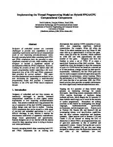
Figure 1. ATDH2200E Configurator Programming Board
In-System Programming Connector
Figure 2. In-System Programming Header
SW1
SW1
(1)
SW2
SW2
(1)
(2)
Notes:
1. SW1 and SW2 are designed to be used for special cascaded EEPROM circuitry in the future. SW1 and SW2 are connected to pin 3 and pin 4 of the parallel port on the ATDH2200E board (Rev.12). 2. Pin 10 activates SER_EN on target board
The ATDH2200E programming board has a 10 pin header (0.1" spacing) to facilitate in-system programming (Figure 2) of the AT17 parts. The control signals generated by the software are fed to the header, as well as to socket U3 on the board. By placing a similar socket on the target system and connecting the programming board to that target system, the programming algorithms written by Atmel can be used to program an AT17 device in-system.
2
ATDH2200E 0642E–CNFG–04/02
ATDH2200E Related Documents
Adapters Available for the ATDH2200E
•
ATDH2200E Programming Kit User Guide
•
AT17 Series datasheet
•
Programming Specification for Atmel’s FPGA Configuration EEPROMs
•
In-System Programming Cascaded Configurators
•
AT17A Series datasheet
•
ATDH2222 – 20-lead PLCC adapter (supplied with kit)
•
ATDH2221 – 20-lead SOIC adapter
•
ATDH2223 – 8-lead SOIC adapter
•
ATDH2224 – 44-lead TQFP
•
ATDH2226 – 32-lead TQFP
•
ATDH2227 – 44-lead PLCC (non-A parts only)
•
ATDH2227A – 44-lead PLCC (A parts only)
•
ATDH2228 – 8-lead LAP
3 0642E–CNFG–04/02
4
A
B
C
D
5
4
2 4 6 8 10
20 VCC 19 DATA CLK SER_EN* 18 RESET/OE* CEO*/A2 17 GND 16 CE* NC 15 NC NC AT17LVXX NC 14 NC 13 NC NC 12 NC NC 11 NC NC NC
U3
1 3 5 7 9
2 4 6 8 10
VCC
NC5 NC6 NC7 NC8
4
SEREN
1
PGM
CE RESET_OE SW2
IN-CIRCUIT PROGRAMING
DATA 1 CLK 3 SW1 5 7 9
U1
Pin 10 activates "SEREN*" on targey board. Pin 9 is the polarizing pin (cut off).
Pin 6 is A2 when in programming mode
1 2 3 4 5 6 NC1 7 NC2 8 NC3 9 NC4 10
DATA CLK RESET_OE CE
5
R3 4.7K
JP1
3
C1 0.1 uF
C2 0.1 uF
VCC VRFY
VCC
3
3
SELECT_IN INIT CLKIN D0
1A1 1A2 1A3 1A4 2A1 2A2 2A3 2A4 1G 2G
U2 1Y1 1Y2 1Y3 1Y4 2Y1 2Y2 2Y3 2Y4 VCC GND
Data
18 16 14 12 9 7 5 3 20 10
VCC
0.1 uF
C3
ACK RESET_OE CE
DATA
R1 4.7K
P1
Date: Friday, April 05, 2002 2
Document Number: ATDH2200 (CHW 5450)
1
1
CLK
1
NC1 AUTO FEED D0 DATA_IN SW1 INIT SW2 SELECT_IN NC2 GND NC3 GND NC4 GND NC5 GND CLKIN GND ACK GND NC6 GND NC7 GND NC8
Sheet
220 ohm
R2
DB25
1 14 2 15 3 16 4 17 5 18 6 19 7 20 8 21 9 22 10 23 11 24 12 25 13
Title: FPGA CONFIGUATOR / PROGRAMMER
HARRISCD74LPT244
2 4 6 8 11 13 15 17 1 19
Tri-State BiDir
VCC
2
of
2
Size A - Rev 12
A
B
C
D
Schematics
Programming Connections
ATDH2200E
0642E–CNFG–04/02
2
A
B
C
9V DC 500 mA
DC IN
J1
3 2 1
5
SM6T18CA 1 2
U4
SPDT
SW1 1
3 4 +
4
DF10S
~ ~
J3
3
2
4
2 1
100uF/25V C6 +
1
3
3
C7 0.1 uF
V1
VO
LC7805CT GND
0642E–CNFG–04/02 2
D
5
3
2
1 +
VCC
2
Date: Friday, April 05, 2002
Document Number: ATDH2200 (CHW 5450)
Title: FPGA CONFIGUATOR / PROGRAMMER
B2S
J2
5.0V
2
Sheet
C5 100 uF
2 1
LED
D1
of
2
Size A - Rev 12
R4 330 ohms
1
A
B
C
D
ATDH2200E
Power Supply Generation
5
Atmel Headquarters
Atmel Operations
Corporate Headquarters
Memory
2325 Orchard Parkway San Jose, CA 95131 TEL 1(408) 441-0311 FAX 1(408) 487-2600
Europe
2325 Orchard Parkway San Jose, CA 95131 TEL 1(408) 441-0311 FAX 1(408) 436-4314
Theresienstrasse 2 Postfach 3535 74025 Heilbronn, Germany TEL (49) 71-31-67-0 FAX (49) 71-31-67-2340
Microcontrollers
Atmel Sarl Route des Arsenaux 41 Case Postale 80 CH-1705 Fribourg Switzerland TEL (41) 26-426-5555 FAX (41) 26-426-5500
2325 Orchard Parkway San Jose, CA 95131 TEL 1(408) 441-0311 FAX 1(408) 436-4314 La Chantrerie BP 70602 44306 Nantes Cedex 3, France TEL (33) 2-40-18-18-18 FAX (33) 2-40-18-19-60
Asia Room 1219 Chinachem Golden Plaza 77 Mody Road Tsimhatsui East Kowloon Hong Kong TEL (852) 2721-9778 FAX (852) 2722-1369
RF/Automotive
ASIC/ASSP/Smart Cards
Japan 9F, Tonetsu Shinkawa Bldg. 1-24-8 Shinkawa Chuo-ku, Tokyo 104-0033 Japan TEL (81) 3-3523-3551 FAX (81) 3-3523-7581
1150 East Cheyenne Mtn. Blvd. Colorado Springs, CO 80906 TEL 1(719) 576-3300 FAX 1(719) 540-1759
Biometrics/Imaging/Hi-Rel MPU/ High Speed Converters/RF Datacom Avenue de Rochepleine BP 123 38521 Saint-Egreve Cedex, France TEL (33) 4-76-58-30-00 FAX (33) 4-76-58-34-80
Zone Industrielle 13106 Rousset Cedex, France TEL (33) 4-42-53-60-00 FAX (33) 4-42-53-60-01 1150 East Cheyenne Mtn. Blvd. Colorado Springs, CO 80906 TEL 1(719) 576-3300 FAX 1(719) 540-1759 Scottish Enterprise Technology Park Maxwell Building East Kilbride G75 0QR, Scotland TEL (44) 1355-803-000 FAX (44) 1355-242-743
Atmel Programmable SLI Hotline
e-mail
(408) 436-4119
[email protected]
Atmel Programmable SLI e-mail
Web Site
[email protected]
http://www.atmel.com
FAQ Available on web site © Atmel Corporation 2002. Atmel Corporation makes no warranty for the use of its products, other than those expressly contained in the Company’s standard warranty which is detailed in Atmel’s Terms and Conditions located on the Company’s web site. The Company assumes no responsibility for any errors which may appear in this document, reserves the right to change devices or specifications detailed herein at any time without notice, and does not make any commitment to update the information contained herein. No licenses to patents or other intellectual property of Atmel are granted by the Company in connection with the sale of Atmel products, expressly or by implication. Atmel’s products are not authorized for use as critical components in life support devices or systems. ATMEL ® is the registered trademarks of Atmel. Microsoft®, Windows ® and WindowsNT ® are the registered trademarks of Microsoft Corporation. Other terms and product names may be the trademarks of others.
Printed on recycled paper. 0642E–CNFG–04/02
xM