Abstract: A fundamental resource in all communication systems and especially in .... implement the MATLAB DSP algorithms on the FPGA while the Xilinx ...
FPGA design considerations for non-orthogonal FDM signal detection R C Grammenos† and I Darwazeh† † University College London
Abstract: A fundamental resource in all communication systems and especially in wireless networks which comes at a premium is capacity. While there is a myriad of external factors influencing system capacity, one of the key issues is spectrum availability. Researchers around the globe are therefore constantly trying to invent novel spectrally efficient techniques to improve bandwidth efficiency. SEFDM is an example of such a technique, which promises to yield significant bandwidth gains.
1. Introduction. Capacity is of uttermost importance in future mobile communication systems, taking into account that one of the key requirements set by the International Telecommunication Union radio sector (ITU-R) is the support of higher data rates in the region of gigabits per second (Gbps). The idea of employing spectrally efficient multicarrier systems to enhance capacity is not new. A number of techniques have been proposed over the years with relevant examples including Fast Orthogonal Frequency Division Multiplexing (FOFDM), M-ary Amplitude Shift Keying (MASK) OFDM, High Compaction Multicarrier Communication Modulation (HC-MCM) and Overlapped FDM (Ov-FDM). [1] Spectrally Efficient FDM (SEFDM) is a form of multicarrier transmission similar to OFDM in that it overlaps the subcarriers to increase spectrum efficiency. Contrary to OFDM though, the overlapping does not retain the orthogonality between the subcarriers giving rise to inter-carrier interference (ICI). As a result, complex detection techniques are necessitated at the receiver to recover such signals. It has been found [1] that the performance of an SEFDM system depends on the number of carriers and/or the level of bandwidth compression, the latter being directly proportional to the relative spacing between the subcarriers. A simplified system diagram of an SEFDM system is shown in Figure 1.
Figure 1: Simplified diagram of an SEFDM system A number of SEFDM transmitter architectures have been investigated [1], which are designed to meet different application needs and have varying levels of implementation complexity. However, the transmission of SEFDM signals is beyond the scope of this study and the reader is directed to reference [1] for in-depth information. The focus throughout the remainder of this report will be on the hardware implementation of digital signal processing (DSP) algorithms for the detection of SEFDM signals using field programmable gate arrays (FPGAs). This paper is organised as follows: In Section 2, we provide an overview of the equalisation and detection techniques commonly employed in wireless communication systems. In Section 3, we consider the design issues associated with FPGA prototyping. Section 4 describes the methodology that will be adopted for the rapid prototyping of DSP algorithms. Finally, Section 5 concludes the paper and outlines future work.
2. Equalisation and detection. A number of equalisation and detection techniques can be used to reconstruct the original signal which trade off computational complexity with bit error rate (BER) performance. As mentioned earlier, the violation of the orthogonality between the subcarriers in SEFDM means that the receivers have a more complicated structure which enables them to recover such signals. The most popular techniques
include the zero-forcing equaliser (ZF-E), the minimum mean square error equaliser (MMSE-E), the maximum likelihood sequence estimator (MLSE) and the sphere decoder (SD). In wireless, high data-rate applications, especially in outdoor scenarios, equalisation is used to counterfeit the effects of inter-symbol interference (ISI). For linear equalisers, there is a trade-off between interference mitigation and noise enhancement. Non-linear equalisers are less sensitive to noise enhancement but come at the expense of increased computational complexity. [2] For sequence estimators, such as the MLSE and the SD, an orthonormalisation process is required to initialise the algorithm. This process is carried out using the Gram-Schmidt (GS) procedure or one of its variants, each offering a different degree of accuracy depending on the rounding errors. [1] Linear equalisers work by inverting the channel frequency response, thus ISI can be completely eliminated. Nevertheless, the noise that arrives at the input of the equaliser is likely to be coloured meaning that the power spectrum will no longer be constant. Hence, noise levels will be amplified leading to the degradation of the system’s signal-to-noise ratio (SNR). This is particularly true for frequency-selective channels, where deep fades or spectral nulls are present in the channel’s frequency response which could result in an infinite noise power. [2] The ZF-E is essentially a digital implementation of an analogue, low-pass equalising filter. It mitigates ISI by simply inverting the channel frequency response, thus may lead to severe noise enhancement. Although the ZF-E may be implemented as a finite impulse response filter (FIR), sometimes it may not be possible to find a finite set of filter coefficients, in which case we need to resort to infinite IR (IIR) filters or alternatively tune the tap weights to minimise the peak distortion. [2] It should be noted that the ZF-E requires the system under equalisation to be invertible. The MMSE-E minimises the MSE between the transmitted symbol and its estimate at the output of the equaliser. In the absence of noise, it is equivalent to a ZF-E. In the presence of coloured noise, the MMSE offers an improved BER performance since it consists of a noise whitening component, thus maintaining the noise floor at a constant power level. Figure 2 gives a generalised example of a linear equaliser with the matched filter and noise whitening components commonly employed in practice.
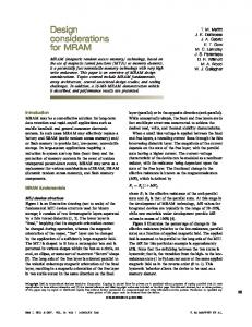
Figure 2: A typical linear equalisation and detection process The matched filter is used to maximise the SNR in the presence of noise prior to the equalisation process. We conclude our talk on linear equalisation by pointing out that the MMSE algorithm is essentially a linear estimation problem which requires the computation of the optimal filter coefficients to minimise the estimation error. [2] The MLSE and SD are non-linear detection techniques which estimate the sequence of the transmitted symbols instead of employing an equalisation filter. The aim of the MLSE algorithm, which depends only on the sampled received signal and the channel parameters, is to maximise the likelihood of the received signal. Although the ML technique offers the optimum solution, it also has the highest computational complexity. Numerous algorithms have been proposed over the last decades to reduce the ML complexity, one of the most widely used ones being the Viterbi algorithm. [2] The SD is a lattice code decoder which performs ML at a much reduced complexity. It achieves this by transforming all possible combinations of the transmitted symbols into a curved lattice and then searches for a point in the lattice that matches the received statistics vector. The radius of the lattice determines the complexity of the algorithm. [1] The SD is preceded by a ZF-E, which in turn is followed by two computationally intensive processes, namely orthonormalisation and Cholesky decomposition, as shown in Figure 3.
Figure 3: Typical steps involved in an SD algorithm
A combination of MMSE and ML was found [1] to provide better error performance with a reduced complexity when compared to ML. It achieved this by initially applying the MMSE algorithm to extract a first estimate of the transmitted symbols, followed by an MLSE on the neighbourhood of the estimate. While this combined technique significantly reduced complexity, the performance was limited by the number of subcarriers and/or the level of bandwidth compression. In conclusion, non-linear equalisers provide performance gains over their linear counterparts with the MLSE setting the performance upper bound. Yet, high performance comes at high computational complexity, which for an SEFDM system is directly proportional to the size of the system in terms of the number of carriers and/or the constellation size. [1] Suboptimum linear methods are conceptually easier to understand and offer an acceptable BER performance for good channel conditions where the channel frequency response is relatively flat and the noise is white. While performance metrics for comparing equalisation and detection algorithms include computational complexity, convergence rate and numerical stability, an entire new set of design constraints and performance indicators enters the scene when these DSP algorithms are implemented in hardware in a real environment.
3. FPGA design considerations. Prototyping of DSP algorithms using FPGAs can be accomplished in numerous ways. In [3], a rapid prototyping methodology using Mathworks and Xilinx tools is proposed. With this methodology, the complete system is initially implemented in MATLAB. Xilinx System Generator is then used to implement the MATLAB DSP algorithms on the FPGA while the Xilinx synthesis tools are used to synthesize the design. Finally, Simulink is employed to create a testbench and along with Xilinx Chipscope software, allows real-time, in system debugging. Even though this MATLAB/Xilinx cosimulation is a simple and effective solution to test DSP algorithms in the real world, it does not allow the DSP algorithm engineer to view the VHDL implementation, therefore could render the troubleshooting and optimisation of the design tedious and troublesome in the long-term. The limiting factor of FPGAs is their availability of hardware resources which include flip-flops (FFs), look-up tables (LUTs), memory blocks and multipliers, the latter being the premium resource. Resource utilisation depends on the logic complexity of the algorithm, which in turn determines the amount of parallel processing and bit precision required. There are complex trade-offs between resource utilisation and the FPGA’s performance. For example, a reduction in the number of multipliers may result in an increase in the number of FFs and LUTS, as the multiplication elements will be replaced by shift, add and sorting operations. The configuration of an FPGA’s resources depends heavily on the application under consideration. Adding more pipelining stages will increase the system’s overall throughput at the expense of additional FFs. Using the same FPGA board to implement algorithms with an increasing level of complexity will result in a comparable reduction in throughput. [3] In systems where synchronisation is of vital importance, as in OFDM, additional FFs have to be incorporated in the design to create delay elements in order to synchronise the different parts of the system, thus taking up more resources and adding latency to the system. Finally, we need to consider that the configuration of the synthesis tools will also have an impact on the resources occupied by a particular design. [4] The ultimate goal is to ensure that all design blocks are active on each clock cycle to optimise the FPGA’s resources.
4. Hardware implementation methodology. For the FPGA prototyping of the SEFDM system under consideration, the DSP algorithms will be implemented using very high speed integrated circuit hardware description language (VHDL). The key challenge that will be encountered during this work is the non-trivial implementation of matrix computations in VHDL while ensuring the design leverages the FPGA’s parallel processing capabilities and embedded multipliers. These computations have a direct impact on the BER performance hence their correct operation in hardware is crucial.
While implementing DSP algorithms directly in VHDL will prove to be a tedious task, it will give us greater flexibility and make it easier in the long-term to debug our code and optimise our design. This is further supported by the fact that many standardised blocks limit the parameters that can be tuned.
Figure 4: Simplified diagram of a practical SEFDM system implementation Figure 4 clearly demonstrates the flexibility offered by our design and verification platform. Signals can be generated directly using MATLAB or through an FPGA transmitter. In the latter case, VHDL code has to be written to program the FPGA accordingly. Testbenches cut down the design time by enabling the engineer to verify the functionality of the VHDL code to a high degree of accuracy, thus reducing the number of unsuccessful synthesis attempts. The same options are available at the receiver for the inverse operations. Several test equipment and measurement devices are used to monitor the signals at the input and output terminals of the FPGA devices while MATLAB is used for spectrum analysis and data representation on a standard computer terminal.
5. Conclusions. The key drawback with OFDM is the constraint imposed upon the spacing between the subcarriers, which in turn restricts the maximum achievable spectrum efficiency. This restriction is alleviated by SEFDM by compressing the bandwidth. While the MLSE is the optimum detector for the recovery of signals distorted by the wireless channel, the algorithm suffers from an impractical computation complexity, which grows exponentially in proportion to the size of the system, in terms of the modulation scheme used, the number of subcarriers, as well as the number of antennas employed. Our aim is to leverage all the design, simulation and synthesis tools available to us to create a platform that will enable us to devise, implement and test DSP algorithms in real-time on the fly. System performance will be evaluated in terms of implementation complexity, throughput and BER. The ultimate goal is to assess the practical feasibility of computer-based simulations for the existing SEFDM transmitter and receiver algorithms, as well as those under development.
References. [1] S. I. A. Ahmed, “Spectrally Efficient FDM System for Wireless Communications,” MPhil / PhD Transfer Report, University College London, 2010. [2] A. Goldsmith, “Equalization”, Wireless Communications, Cambridge University Press, New York, USA, 2005, Chapter 11. [3] M. Joham, L. G. Barbero, T. Lang, W. Utschick, J. Thompson, T. Ratnarajah, “FPGA implementation of MMSE metric based efficient near-ML detection,” Smart Antennas, International ITG Workshop on WSA, pp.139-146, 26-27 Feb. 2008 [4] Xilinx Inc.: http://www.xilinx.com/