For many applications from the areas of cryptography and coding, finite field multiplication is ... digital signature algorithms and proposed by NIST 2. This stan-.
FPGA DESIGNS OF PARALLEL HIGH PERFORMANCE GF(2233 ) MULTIPLIERS C. Grabbe, M. Bednara, J. Teich
J. von zur Gathen, J. Shokrollahi∗
Computer Engineering Laboratory University of Paderborn Paderborn, Germany
Algorithmic Mathematics University of Paderborn Paderborn, Germany
ABSTRACT For many applications from the areas of cryptography and coding, finite field multiplication is the most resource and time consuming operation. We have designed and optimized four high performance parallel GF (2233 ) multipliers1 for an FPGA realization and analyzed the time and area complexities. One of the multipliers uses a new hybrid structure to implement the Karatsuba algorithm. For increasing performance, we make excessive use of pipelining and efficient control techniques and use a modern state-of-the-art FPGA technology. As a result we have, to our knowledge, the first hardware realization of subquadratic arithmetic and currently the fastest and most efficient implementation of 233 bit finite field multipliers. 1. INTRODUCTION Finite field arithmetic plays a major role in cryptography and coding theory. Among different operations in finite fields, multiplication is the most resource and time consuming task in hardware and software implementations as well. (Division, however, is much costlier than multiplication but there are efficient techniques to decompose a division into a sequence of multiplications (see [1]), or to avoid division in many cases). This work is intended to help a hardware designer to make the best selection for an FPGA based parallel field multiplier for a given finite field. Especially for the area of cryptography where the extension of the finite field GF (2n ) is fairly large, say n > 160, the selection of the multiplication algorithm has a major impact on the overall system performance. In this work we analyze FPGA implementations of four known parallel multipliers in GF (2233 ). The selection of the finite field is based on the FIPS 186-2 standard ([2]) concerning with the digital signature algorithms and proposed by NIST 2 . This standard suggests 5 binary fields, mainly the extension degrees 163, 233, 283, 409, and 573, which are all prime extensions. We have selected GF (2233 ) to satisfy the security requirements in elliptic curve cryptography for the next years, but our results can be adapted to finite fields with other prime extensions as well. For cryptography, the requirements with respect to performance and security may change depending on the application. For this reason we use FPGAs as target technology in order to avoid the flexibility lacking in ASIC designs. It turns out that many opti∗ This work is supported by DFG Sonderforschungsbereich 376 “Massive Parallelit¨at.” 1 Galois field 2 National Institute of Standards and Technology
0-7803-7762-1/03/$17.00 ©2003 IEEE
mizations of field multipliers proposed for ASIC design do not hold for FPGA. The main differences are • Influence of routing on the FPGA performance. • 4-input lookup table technology instead of 2-input logic gates. • Treatment of high-fanout nets on FPGAs. So we decided to create completely new FPGA optimized designs for the multipliers. The paper is organized as follows. In the next section we give an overview over related work. Section 3 gives a short introduction into the theory of operation of the classical, Karatsuba, MasseyOmura and Sunar-Koc¸ multipliers. The architecture and FPGA implementation of these multipliers is described in detail in Section 4. The performance results and a comparison is given in Section 5 and a summary in Section 6. 2. RELATED WORK Several works concern the comparison of different hardware based multiplier architectures in the binary finite fields. The authors of [3] have compared three known serial multipliers, namely Berlekamp, Massey-Omura, and a polynomial basis multiplier, and implemented them for a small finite field GF (28 ) in VLSI. [4] considers VLSI implementation of parallel multipliers for a class of finite fields GF (2n ) with extension degrees n = 8, 16, 24, and 32, which are not prime extension degrees and are believed to have security weaknesses ([5]). [6] considers different parallel multipliers in GF (24 ) which is suitable for coding applications. This work also considers hardware optimization techniques to improve the performance of multipliers and make some estimates which hold only for small finite fields. [7] gives a detailed comparison of different VLSI implementations of parallel multipliers in GF (24 ). Indeed all of the above works (except [4]) correspond to small finite fields and the results can not be easily extended to larger fields. With the development of new FPGA families with large gate counts, however, it is possible to realize parallel finite field multipliers on a single chip which performs the total multiplication operation in a few clock cycles. So it becomes necessary to have a performance analysis of the multipliers for large field extensions (with n > 160) to select the best multiplier for a certain application. 3. MULTIPLICATION IN THE BINARY FINITE FIELDS There are several algorithms to multiply two finite field elements and each of them has its benefits depending on the finite field size,
II-268
the implementation type (hardware or software), and the time and area requirements. One of the main differences between these algorithms is the finite field representation basis. In this section we give a brief introduction of different hardware based finite field multipliers in GF (2n ) along with their space and time complexities. When the Hamming weight of the irreducible polynomial plays a significant role, we assume the existence of an irreducible trinomial of degree n when considering the multiplication in GF (2n ). This is a reasonable assumption since our special finite field is GF (2233 ), and the polynomial x233 + x74 + 1 is irreducible. On the other hand it is conjectured that a trinomial of degree n exists for a large amount of values n (see [1]). Multipliers will be categorized depending on the finite field basis.
3.1. Polynomial Basis Multipliers In this basis, each element is represented as a linear combination of different powers of a root of an irreducible polynomial. Indeed multiplication in this basis consists of a polynomial multiplication followed by a modular reduction. There are different possibilities to multiply two elements in this basis like the Mastrovito, the classical, and the Karatsuba multipliers. Since there is only small difference in time and space complexities of the Mastrovito and the classical multipliers we select the classical multiplier because of its regular structure and the possibility of pipelining which is difficult to apply to the Mastrovito multiplier.
3.1.1. Classical Multiplier The most straightforward method to perform finite field multiplication is to multiply the polynomials and then reduce the result modulo an irreducible polynomial to achieve the final result. The school method polynomial multiplication requires n2 AND gates and (n − 1)2 XOR gates (2-input each). The combinatorial propagation delay across a school method multiplier is T = TAN D + dlog2 neTXOR . Reducing modulo the polynomial f (x) can be done using (r − 1)(n − 1) two input XOR gates, where r and n are the Hamming weight and the degree of the polynomial f (x), respectively.
3.1.2. Karatsuba Multiplier An approach to reduce the number of gates in the polynomial basis multipliers is the Karatsuba method (see [8] and [9]). In this method the number of multiplications is reduced but at the cost of increasing the number of additions and the total propagation delay. This method decreases the total number of gates from O(n2 ) to the O(n1.59 ), which is very effective when the polynomials become large. To achieve a tradeoff between the area and propagation delay which is long in the Karatsuba multipliers, we have used a hybrid structure by using the Karatsuba multiplication formulas (see [10]) for the polynomials of degree 1 and 2 in a hierarchical manner above school method multipliers of degree 39. This structure requires 28800 AND and 31183 XOR gates, and a total propagation delay of TAN D + 14TXOR . The costs for a pure Karatsuba multiplier are 6561 AND, 37320 XOR, and TAN D + 26TXOR and for a school method multiplier are 54289 AND, 53824 XOR, and TAN D + 8TXOR .
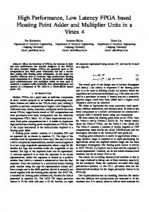
3.2. Normal Basis Multipliers An element α in GF (2n ) is called a normal element, when the eli ements of the set Γ = {α2 |0 ≤ i < n} are linearly independent. In this case, the set Γ is called a normal basis. One great advantage of the normal bases is that squaring in this basis consists of only a cyclic shift (which requires no logic elements and can be done in nearly zero time). There are two types of normal bases for which there exist effective multiplication methods, namely optimal normal bases of type I, and II. 3.2.1. Massey-Omura Multiplier The Massey-Omura multiplier is one of the most famous multipliers that work in the normal basis representation. It consists of similar blocks which can work in parallel to generate output bits simultaneously. One great advantage of this multiplier is its flexibility as a serial-parallel multiplier. This means that the designer has the ability to select an arbitrary number of similar blocks to achieve different numbers of output bits in one clock cycle, depending on the given area constraints. For the case of optimal normal bases in GF (2n ) one requires (2n − 2)D 2-input XOR and nD 2-input XOR gates, where D is the number of output bits per clock cycle. The minimum combinatorial propagation delay is TAN D + dlog2 neTXOR . (See [4].) 3.2.2. Sunar-Koc¸ Multiplier The Sunar-Koc¸ multiplier is a fully parallel multiplier which generates all output bits simultaneously, see [11]. It uses a normal basis representation and requires significantly less gates than a full parallel Massey-Omura ( 25 n2 − 23 n 2-input gates). The minimum combinatorial delay is the same as of the Massey-Omura multiplier. 4. FPGA IMPLEMENTATIONS OF PARALLEL MULTIPLIERS In this section we present the architectures of the parallel multipliers we have implemented. All multipliers are synthesized for a Xilinx Virtex-2 FPGA (xc2v-6000-ff1157-4). The interface logic is the same for all multipliers so we can use the same testbench and the designs are interchangeable. 4.1. The Classical Multiplier The implemented classical multiplier consists of a polynomial multiplier followed by the modular reducer (Figure 1). Assuming that the polynomial c = c2n−2 x2n−2 + c2n−3 x2n−3 + · · · + c1 x + c0 is the product of two polynomials a = an−1 xn−1 + an−2 xn−2 + . . . a1 x + a0 and b = bn−1 xn−1 + bn−2 xn−2 + . . . b1 x + b0 , then the different coefficients of c can be computed using the equation (1). c0 =
a0 b 0
c1 =
a0 b 1 +
cn−1 =
a0 bn−1 +
a1 b0 ... a1 bn−2 +
. . .+
an−2 b1 +
an−1 b0 (1)
... c2n−3 = c2n−2 =
II-269
an−2 bn−1 +
an−1 bn−2 an−1 bn−1
Each of the rows of (1) has some elements which must be combined in a XOR tree to generate a single bit of the result. The rows ci and c2n−2−i for 0 ≤ i < n − 1 are generated with tree structured XOR-circuits of identical length, but with different inputs. So we have a total of 465 XOR trees, where 464 of them are pairwise equal in size 3 .
Since outputs of the different multipliers have some powers of x in common, the overlap circuit XORs the overlapping powers. The same structure is used in each of the 80-bit multipliers. Each of the 40-bit multipliers is a classical polynomial multiplier and has the same structure as used in Section 4.1, but of much smaller size. 4.3. Massey-Omura Multiplier
A
B
permutation �
� �
�
�
�
�
��
� �
�
233
�
� �
XOR_233
232
� �
� �
XOR_232
...
232
�
2
...
�
1 XOR_1
��
�
�
2 XOR_2
XOR_1
Control Circuit
�
1 �
� �
��
XOR_2
�
� �
XOR_232
�
�
� �
Modular Reducer
Fig. 1. Classical multiplier for 233 Bit An earlier design of ours which used only 233 trees but additionally 232 multiplexers required more clock cycles and exceeded the FPGA resources, so we decided to use the full number of XOR trees.
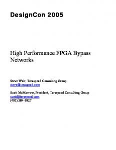
If implemented fully in parallel, the resource requirements of the Massey-Omura multiplier are very large (exceeding the LUT4 resources of our FPGA by about 7 percent), but it can be realized with any degree of parallelism between fully parallel and fully serial. So we use a semi-parallel implementation where a multiplication is performed in two steps. As shown in Figure 3, Massey-Omura consists of two cycshiftstages5 with 117 outputs each. Output n is the same as output n − 1 but cyclically rotated by one bit. The 117 rotated operand pairs are passed in parallel to 117 identical XOR trees (XOR 1 ... XOR 117) that compute the lower 117 bits of the result. The last outputs of the cycshift stages are fed back to the inputs via an operand register, so the second set of rotated operands as well as the higher part of the result is generated one clock cycle later.
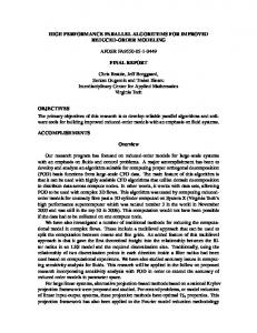
4.2. The Hybrid Karatsuba Multiplier We have used a hybrid structure to combine the Karatsuba algorithms (see 3.1.2) with 2 and 3 coefficients respectively to generate a Karatsuba algorithm with 6 coefficients. Furthermore, we have used a new distributed control structure to implement the polynomial multiplication. The combination of these two Karatsuba methods has already been proposed in [12] for composite extension finite fields and [10] for the Optimal Extension fields. But to our knowledge, it is the first time that such a combination has been implemented in hardware for prime extension finite fields. The block diagram of the complete multiplier is shown in Figure 2. Karatsuba 80
Karatsuba 80
40bit Adder
40bit Adder
40bit Adder
40bit Adder
40bit Adder
40 bit Multiplier 40 bit Multiplier
40 bit Multiplier 40 bit Multiplier
Control Circuit
40bit Adder
Control Circuit
Control Circuit
Control Circuit
Karatsuba 80
40 bit Multiplier
4.4. Sunar-Koc¸ Multiplier 80 bit Adder 80 bit Adder 80 bit Adder
40 bit Multiplier
80 bit Adder 80 bit Adder
40 bit Multiplier
40 bit Multiplier
40 bit Multiplier
Overlap Circuit
Overlap Circuit
Overlap Circuit
Fig. 3. Semi-parallel Massey-Omura multiplier
80 bit Adder
Overlap Circuit Modular Reducer
Fig. 2. Hybrid parallel Karatsuba multiplier for 233 Bit The multiplier in the upper level consists of three 80-bit multipliers, six 80-bit adders, and the overlap circuit. Each of the multipliers will be used twice during a polynomial multiplication to cover the total six 80-bit multiplications. The control circuit starts the multipliers at the suitable time to make use of the pipeline stages in the multipliers. It also controls the timing of the adders. 3 Indeed the XOR trees corresponding with the first and the last equations consist of only AND gates, but we have used the general word XOR tree.
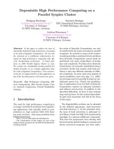
Like Massey-Omura, Sunar-Koc¸ is a multiplier that works on operands represented in a type-II optimal normal basis. Due to resolving the redundancies in a parallel Massey-Omura multiplier, the required number of logic gates reduces approximately to 75 percent. Sunar-Koc¸, however, is a full-parallel multiplier and cannot be serialized efficiently. Fig. 4 shows the structure of the Sunar-Koc¸ multiplier. The permstages permutate the operand bits und thus realize the basis transformation as described in [11]. The next stage called preprocessor generates all non-redundant terms of the form ai bi and ai bj +aj bi of the operand bits. These 27261 terms are combined to the 233 bit result in 233 parallel identical XOR trees (XOR 1 ... XOR 233). The iperm-stage computes the inverse permutation of the permstages and transforms the result back to the normal basis representation. Perm and iperm stages are very similar and thus implemented in a single component which drastically reduces synthesis time. 6 4 Look
up table shift stages 6 The synthesis time for perm stages however is still extremely long, so we decided to omit the perms from synthesis. Since the perm stages contain no logic elements but only routing, we expect no influence on timing and area. 5 cyclic
II-270
architectures, all pipeline flipflops can be removed without changing the functionality. Routing resources are not taken into account, since VIRTEX-2 FPGA have plenty of routing resources so that the totally occupied chip area is spanned by the slice count of the design and not the routing. The time T is the product of clock periods and number of clock cycles for a complete multiplication in GF (2233 ). This allows to evaluate the multiplier performance independently from the number of pipeline stages. 6. SUMMARY
Fig. 4. Parallel Sunar-Koc¸ multiplier
5. RESULTS In this section we give the performance comparison of the FPGA synthesis results. All multipliers are synthesized for a Xilinx xc2v6000-ff1517-4 FPGA without pin mapping and area constraints. In subsequent synthesis iterations, we specified timing constraints with slightly increasing stringency in order to converge to an optimal timing. It should be noted that the clock cycle time is computed including the pad delays since all multipliers are implemented as ”stand alone” designs. Multiplier
LUT/FF
Classical(estmd.)
37296 / 37552
equivalent gate count 528427
HybridKaratsuba
11746 / 13941
182007
MasseyOmura
36857 / 8543
289489
SunarKoc¸
45435 / 41942
608149
clock period (Frequency) ∼13.00ns (∼77 MHz) 11.07ns (90.33Mhz) 15.91ns (62.85MHz) 10.73ns (93.20MHz)
Table 1. Area requirements and minimum clock periods of multipliers. Table 1 gives a comparison of the number of 4-input LUTs, the number of flipflops, the equivalent gate count (as reported by the vendor synthesis tools), and the clock period for each multiplier. Due to a misoperation of our synthesis framework, we could not complete the synthesis of the classical multiplier, thus the values are estimated. 7
Fig. 5. AT (left) and AT 2 (right) comparison of the multipliers Fig. 5 shows the AT and AT 2 criteria. The area A we define as the sum of the LUTs and flipflops. It should be noted that the majority of the flipflops are used for internal pipeline stages and it is possible to design all multipliers with a significantly smaller number of flipflops (e.g. about 700 for Sunar-Koc¸). In fact, in our 7 The
number of LUTs and FFs, however, can be estimated fairly exact.
We have analyzed our own high performance FPGA implementations of parallel GF (2233 ) multipliers, namely Classical, Karatsuba, Massey-Omura, and Sunar-Koc¸, with respect to area and time complexity. Especially for Karatsuba, we used sophisticated control structures the first time for prime degree extension field multipliers. It turned out that for polynomial basis representation, Karatsuba is the best choice while for normal basis the Sunar-Koc¸. All parallel multipliers can operate at high clock rates and require only few clock cycles for a complete operation, but have extraordinary resource requirements. We have shown, however, that they can be implemented efficiently on modern FPGAs which allows for high performance FPGA based cryptographic applications. To our knowledge, we have currently the fastest FPGA designs for parallel finite field multipliers of that size. 7. REFERENCES [1] Joachim von zur Gathen and Michael N¨ocker, “Exponentiation using addition chains for finite fields,” in preparation, 2002. [2] U.S. Department of Commerce / National Institute of Standards and Technology, Digital Signature Standard (DSS), January 2000, Federal Information Processings Standards Publication 186-2. [3] I. S. Hsu, T. K. Truong, L. J. Deutsch, and I. S. Reed, “A comparison of VLSI architecture of finite field multipliers using dual, normal, or standard basis,” IEEE Transactions on Computers, vol. 37, no. 6, pp. 735–739, June 1988. [4] Christof Paar and Nikolaus Lange, “A Comparative VLSI Synthesis of Finite Field Multipliers,” in Proceedings of the 3rd International Symposium on Communication Theory & Application, Lake District, UK, July 1995. [5] Niegel. P. Smart, “How Secure Are Elliptic Curves over Composite Extension Fields?,” in Advances in Cryptology: Proceedings of EUROCRYPT 2001, Aarhus, Denmark, B. Pfitzmann, Ed. 2001, number 2045 in Lecture Notes in Computer Science, pp. 30–39, SpringerVerlag. [6] C. Gregory, C. Ahlquist, B. Nelson, and M. Rice, “Optimal finite fields for FPGAs,” in Proceedings of the 9th International Workshop on Field Programmable Logic and Applications (FPL 99), Glasgow, UK, August 1999, number 1673, pp. 51–61, Springer. [7] Mohamed El-Gebaly, “Finite Field Multiplier Architectures for Cryptographic Applications,” M.S. thesis, Waterloo University, 2000. [8] Donald E. Knuth, The Art of Computer Programming, vol. 2, Seminumerical Algorithms, Addison-Wesley, Reading MA, 3rd edition, 1998, First edition 1969. [9] Joachim von zur Gathen and J¨urgen Gerhard, Modern Computer Algebra, Cambridge University Press, Cambridge, UK, first edition, 1999. [10] Daniel V. Bailey and Christof Paar, “Efficient arithmetic in finite field extensions with application in elliptic curve cryptography,” Journal of Cryptology, 2000, to appear. [11] B. Sunar and C¸. K. Koc¸, “An Efficient Optimal Normal Basis Type II Multiplier,” IEEE Transactions on Computers, vol. 50, no. 1, pp. 83–87, Januar 2001. [12] C. Paar, Efficient VLSI Architectures for Bit-ParallelComputation in Galois Fields, Ph.D. thesis, Institute for Experimental Mathematics, University of Essen, Essen, Germany, June 1994.
II-271