VOLUME: 13 | NUMBER: 1 | 2015 | MARCH
CONTROL ENGINEERING
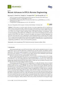
FPGA Implementation of a Simple 3D Graphics Pipeline Vladimir KASIK, Ales KURECKA Department of Cybernetics and Biomedical Engineering, Faculty of Electrical Engineering and Computer Science, VSB–Technical University of Ostrava, 17. listopadu 15, 708 33 Ostrava, Czech Republic
[email protected],
[email protected] DOI: 10.15598/aeee.v13i1.1125
Abstract. Conventional methods for computing 3D projects are nowadays usually implemented on standard or graphics processors. The performance of these devices is limited especially by the used architecture, which to some extent works in a sequential manner. In this article we describe a project which utilizes parallel computation for simple projection of a wireframe 3D model. The algorithm is optimized for a FPGAbased implementation. The design of the numerical logic is described in VHDL with the use of several basic IP cores used especially for computing trigonometric functions. The implemented algorithms allow smooth rotation of the model in two axes (azimuth and elevation) and a change of the viewing angle. Tests carried out on a FPGA Xilinx Spartan-6 development board have resulted in real-time rendering at over 5000 fps. In the conclusion of the article, we discuss additional possibilities for increasing the computational output in graphics applications via the use of HPC (High Performance Computing).
Keywords 3D projection, FPGA, parallel processing, real time, VGA, VHDL.
1.
Introduction
The drawing of graphics scenes in 3D obtained from their representations requires the processing of large volumes of data. Special chips are available for this purpose – GPUs which rely on mass parallelization. Under usual circumstances, CPUs are not suitable for these tasks (even though there do exist instruction sets supporting multiple computations), since by their design they process instructions serially and hence would
require much larger frequencies to achieve comparable speeds. FPGA also support high parallelization and may be used to achieve high computational throughputs. This project originated as a semester project with an initial goal of drawing 3D projections of simple wireframe models in real-time on a single chip, where the intent was to achieve very high values of fps. Since the described problem commonly lies beyond the boundaries of usual microcontrollers/CPUs, the solution has led to the creation of a hardware graphics pipeline for drawing on a screen via the VGA interface [1].
2.
Graphics Pipeline
Current GPUs comprise many cores containing unified shaders, which allow the realization of operations previously carried out by vertex units, pixel units, TMUs (texture mapping units) and ROPs (render output units). Drawing of 3D models on the screen is basically the results of several consecutive blocks (simplified) [5]: • Primitive processing – reading primitives, vertices and their connection. • Vertex shader – the vertex shader transforms coordinates of vertices by their multiplication with the matrices of the scene. This is where the transformation from 3D → 2D occurs. • Primitive assembly – vertices are joined into primitives. • Rasterization – primitives are rasterized into pixels. • Pixel shader – this is applied to each pixel of the rasterized scene and computes its color. This step also applies textures.
c 2015 ADVANCES IN ELECTRICAL AND ELECTRONIC ENGINEERING
39
VOLUME: 13 | NUMBER: 1 | 2015 | MARCH
CONTROL ENGINEERING
A vertex unit (whose functionality is nowadays included in the vertex shader) will suffice for the purposes of this work. The data source is a ROM with the vertices of the model, which is then transformed by the vertex unit to vertices in a plane. These vertices are then joined by line segments and drawn in video RAM, from which the VGA adapter will subsequently generate VGA signal for the screen. The graphics pipeline consists of the unit carrying out the computation of the projection matrix (GrxGenerateProjectionMatrix ) and the unit multiplying the projection matrix with the vertices of the displayed model (GrxVertexProjection). Both GrxGenerateProjectionMatrix and GrxVertexProjection together form the vertex unit and ensure the actual 3D → 2D display. The obtained 2D vertices are scaled to the required size and converted from decimal numbers represented with a fixed decimal point to integers into the monitor coordinates system and stored in the memory cache (the 2D vertex bank). Vertices from the cache are read by the unit drawing the wireframe model based on their connection map (from the ROM model). The model is drawn in the black-and-white video RAM (frame buffer), from which display data are read by the VGA adapter and displayed on the screen.
2.1.
Perspective Projection
Displaying a 3D object in two dimensions is a linear transformation over the R3 vector space into R2 . A special case of this is the projection transformation. This transformation can be described by the projection matrix. During projection, the dimension degrades from dimR3 = 3 to dimR2 = 2 and the vectors obtained by the transformation can be used to display the object on a plane (e.g. a screen). There exist two types of projection which are used in graphics: parallel projections (which include isometric, orthogonal, oblique projections etc.) and perspective projections. In this article we focus on the latter type of projections. Linear perspective projections always work with a representation of the beams from the projected object to the observer’s eye (the camera) through a plane, on which the object is projected. See Fig. 2 for an illustration.
Displaying is ensured by the VGA adapter with binary modulation of base colors. The control of the whole Cubido3D project is ensured by one primary and several local FSMs (Finite State Machines). A simplified diagram of the graphics pipeline is provided in Fig. 2: Perspective projection of an object onto a plane. Fig. 1. The transformation matrix realizing perspective projection is obtained by multiplication of 3 matrices [4]: A = P · T · R.
(1)
• The transformation matrix R, which is obtained by a composition of rotation by axes x and z:
0 0 , 0 1
(2)
0 0 0 0 , 1 0 0 1
(3)
1 0 0 0 cos(θx ) − sin(θx ) Rx = 0 sin(θx ) cos(θx ) 0 0 0
cos(θz ) − sin(θz ) sin(θz ) cos(θz ) Rz = 0 0 0 0 Fig. 1: Simplified diagram of the Cubido3D graphics pipeline.
R = Rx · Rz .
Individual blocks of the graphics pipeline consist of separate VHDL modules or optimized IP cores which are a part of the Xilinx ISE development kit.
Rotation is typically entered in the form of an azimuth and elevation, where the following relations hold:
c 2015 ADVANCES IN ELECTRICAL AND ELECTRONIC ENGINEERING
(4)
40
VOLUME: 13 | NUMBER: 1 | 2015 | MARCH
CONTROL ENGINEERING
where f is the focal distance, which can be computed from the viewing angle:
θz = −θaz , θx = θel −
(5)
π . 2
√
f=
Figure 3 illustrates the effects of the transformation matrix.
Fig. 3: Effects of the transformation matrix on the displayed object.
• The translation matrix T translated the starting point [0, 0, 0] of the coordinate system of the object and has the shape:
0 0 0 0 1 0 T= 0 0 1 0 0 0
vx vy . vz 1
2 , 2 · tan( φ2 )
(9)
φ determines the rate of the projection deformation of the object. If φ = 0, the projection degrades to an orthogonal projection.
Fig. 5: Effect of viewing angle on perspective deformation of the display.
3.
Implementation
The Cubido3D project implements a hardware-based graphics pipeline based on FPGA. Projection, transla(6) tion of objects and generation of video signal is adapted for an architecture based on a programmable logic.
Aside from the graphics pipeline, the project also The translation moves the beginning of the coorincludes a VGA adapter generating the video signal dinate system, usually to the center of the object. for the screen, a memory of displayed models, blocks This forms the center based on which the object generating the background image + panel image and is rotated (Fig. 4). supporting logic (distribution of clock signal, control of the graphics pipeline etc.). Pipelining and strong √ cos(θel ) · sin(θaz ) parallelism are commonly used to obtain the target fre1 3 v= + · − cos(θel ) · cos(θaz ) . (7) quency of 100 MHz. 2 2 sin(θel )
3.1.
Cubido3D
Cubido3D forms the Top Level Module. It synchronizes input signals, controls the azimuths and elevation by counters with acceleration and the viewing angle by a counter with overflow protection. Combinations of buttons also allow the selection of the drawing model and the generation of a global reset. Fig. 4: Effects of the translation matrix on the displayed object.
If the coordinates of object vertices are set so that the object lies in [0, 0, 0], the matrix becomes a unit matrix and the translation is not necessary. • The perspective transformation P carries out the actual conversion from 3D → 2D and has the form:
0 0 P= 0 0
0 1 0 0
0 0 1 − f1
0 0 , 0 d f
f = d,
(8)
The selected data of the model are, together with the azimuth, elevation and viewing angle, transferred to GrxGraphicUnit. Cubido3D connects the VGA adapter and FPs display on a 7-segmented display. Since FPGA doesn’t have sufficient memory for double buffering, video RAM has a capacity of only 1 frame and must thus be redrawn synchronously at the time the screen is in an inactive area. Due to this, redrawing is always called during the receipt of the vertical synchronization impulse. Drawing is fast (takes approximately 200 µs in case of a cube) and thus finishes before the screen transfers to the active area.
c 2015 ADVANCES IN ELECTRICAL AND ELECTRONIC ENGINEERING
41
VOLUME: 13 | NUMBER: 1 | 2015 | MARCH
CONTROL ENGINEERING
divisor. All additional computations are carried out by the DSP48A1 unit which is part of the architecture of the used FPGA. DSP48A1 is specifically configured to carry out the following computation: R = A + (B − C) · D.
(10)
The unit works with numbers with a fixed decimal (FXP) in the 10Q8 format. The computation is illustrated in the Fig. 7:
Fig. 6: Example of an output generated by FPGA captured on a VGA interface.
3.2.
Implementation of the Graphics Pipeline
The graphics pipeline consists of the unit for computing the projection matrix, the vertex unit, the simple rendering unit and a two-port video memory. The pipeline first deletes video RAM, computes the projection matrix with transferred parameters (azimuth, elevation, viewing angle) and reads the normalized 3D model from the vertex memory and their interconnections. This is then displayed in 2D and rescaled for display on the screen (numbers are converted with a certain offset and scale from FXP to integer form). The computer 2D vertices are stored into the small cache. The wireframe model is then drawn in the video memory from the computed 2D vertices. 1)
Calculation of the Projection Matrix (GrxGenerateProjectionMatrix )
GrxGenerateProjectionMatrix is a unit which computes the matrix of a perspective display from received values of the azimuth, elevation and viewing angle (amount of perspective deformation). The computation of formulas Eq. (1) to Eq. (9) is adapted for processing via FPGA. The center of the projection (the target point) is fixed to the initial point of the coordinate system. Despite best efforts to make the computation as parallel as possible, it is strongly sequential and its processing is carried out by a state machine with 28 states. The computation of trigonometric functions is carried out by the CORDIC unit (CordicCore_SINCOS entity), which computes in parallel the sine and cosine functions for the entered angle. The computation of the tangent of the viewing angle is carried out in 2 steps: the first is the computation of the sine and cosine of the viewing angle, followed by their division. Division is carried out in an adjoined serial
Fig. 7: Computation of the projection matrix by the GrxGenerateProjectionMatrix module.
The resulting projection matrix is serialized into a 4×4×10Q8 bus, and thus has a width of 288 bits. The bus is connected to computational units via registers and bus multiplexes controlled by the state automaton. The largest amount of running time is used by the serial divisors, and hence they are initiated shortly after the computation of the matrix begins and they work in parallel with the other computations. 2)
Vertex Unit (GrxVertexProjection)
The vertex unit computes 2D vertices of the image by projecting their 3D template through multiplication with the projection matrix received from GrxGenerateProjectionMatrix . The whole principle is very similar to the computation carried out by the GrxGenerateProjectionMatrix unit. The computation is con-
c 2015 ADVANCES IN ELECTRICAL AND ELECTRONIC ENGINEERING
42
VOLUME: 13 | NUMBER: 1 | 2015 | MARCH
CONTROL ENGINEERING
trolled by a state machine (12 states) together with a divisor and 2 DSP48A1. Both DSP48A1 realize the following computation: R = A + B · D.
(11)
The steps of the computation carried out by the vertex unit are illustrated in the Fig. 8: Fig. 9: One of the models stored in ModelDescriptionROM drawn directly by the graphics pipeline with a detailed view of the rasterization of the wireframe model.
and hence also writing can be stopped by a signal, and if necessary this can be setup by the state machine controlling video memory. The state machine (12 states) first captures, compares and if necessary adjusts the order and coordinates of the input vertices (the unit transforms all line segments into the first half of the first quadrant – angular coefficient 0 to π4 ). This is necessary to allow the generation of coordinate x by a counter; larger coFig. 8: Multiplication of the projection matrix and a vertex. efficients would lead to the loss of points on the line, see Fig. 10. It then computes their angular coefficient Since the computations of vertices are mutually in(the increase in the vertical axis per unit step on the dependent, they can be carried out in parallel in several horizontal axis). The number of the fractional (breakidentical vertex units. line) bits of the angular coefficient is set automatically The coordinates for the templates of vertices are read so as to reach the target vertex. The unit then uses from the model memory by the superordinate state ma- the counter to generate the horizontal coordinate and chine in GrxGraphicsUnit. The obtained coordinates of generates the vertical one by the accumulator. The vertices in the plane are first converted from FXP for- vertical coordinate is rounded. Coordinates are also mat to coordinates on the screen, or more specifically adjusted by the offset specified in point 1 and transin the video memory, and stored in the memory cache formed back into their quadrant. Finally, the write (Vertex2D_Bank ). signal is created. 3)
Wireframe Model Rendering (GrxDrawWireframe)
GrxDrawWireframe draws the wireframe from the 2D vertex bank (Vertex2D_Bank ). The unit reads the connection map between individual vertices from the model memory into the wireframe model, and these vertices are then read from the bank of 2D vertices Fig. 10: Drawing of a line segment and the effect of the angular coefficient. and transferred to GrxDrawLine2D, which draws a line segment between the vertices. Generation of coordinates for a write request is carMemory control is managed by the unit’s own re- ried out in 2 cycles, and the unit is hence capable of drawing 1 pixel per 2 cycles. In general the drawing sources. process takes circa 40 + 2n cycles (where n is the number of drawn points). Interrupts of writing called by 4) Drawing a Line Segment the video memory unit are not taken into account. Fi(GrxDrawLine2D) gure 9 illustrates the generation of a line segment. This unit draws a line segment defined by 2 integer Video Memory (GrxVideoRAM ) 2D vertices into the memory. The vertices need not 5) be ordered or otherwise preprocessing (the unit takes care of this automatically). The speed of generating This module implements the video memory with a points on the line is 1 point per 2 clocks. Generation function for quick deletion of the whole RAM. Read-
c 2015 ADVANCES IN ELECTRICAL AND ELECTRONIC ENGINEERING
43
VOLUME: 13 | NUMBER: 1 | 2015 | MARCH
CONTROL ENGINEERING
ing and writing is realized by a state automaton, which works with a larger internal data bus than the required external one (and hence also a smaller internal address bus). This allows much quicker deletion of RAM. Part of the external address bus (the upper bits) addresses a location in RAM, whereas the lower bits map the external data bus to the greater internal data bus. Writing can in some cases take longer than 1 clock, since it is necessary to first read a data block in RAM, change the corresponding group of bits in this block via the input data for writing and then write this block, as illustrated in Fig. 11. The current block is cached.
1)
Model Memory (ModelDescriptionROM )
The definition of models consists of a list of vertices (Vertex3DBankROM ) and their connections (VertexPointerROM ). Models are stored sequentially. ModelsDescriptorROM is used to store the offset to Vertex3DBankROM and VertexPointerROM, where the model begins and simultaneously the length of the records of the model in these memories. VertexPointerROM consists of a map of vertex connections – it contains tuples of indices (addresses) into Vertex3DBankROM which define a line segment in the wireframe model. Figure 12 illustrates the model memory architecture.
Fig. 11: Video memory architecture.
3.3.
VGA Adapter (GrxAdapterVGA)
A generic VGA adapter which supports various resolutions and color depths based on the configuration of [6]. Its correct operation is based on an incoming signal Fig. 12: Model memory architecture. with a VGA pixel frequency from the main clock distribution through the DCM (Digital Clock Manager) module. Background Video Signal Generator Clock domains are strictly separated. All simple sig- 2) (BackgroundVisualizer ) nals are resynchronized by the GResynchronizer block (part of the library of general project components) and the transmission of video signal from the input clock This takes care of the generation of RGB signals for domain is resolved via a FIFO queue with separated drawing the background in VGA. It draws a vertical clocks for reading and writing. This queue is also used color shift from black. as a line cache (writing is carried out on a line-by-line basis). The queue is inserted as an IP core to ensure timing and synchronization. Synchronization of writing in the line cache is carried out via the LineStrobe (beginning of a line) and FrameStrobe (beginning of a frame) signals in combination with the PixelRequestAxis (current coordinate for writing) signal.
3.4.
Project-Oriented Modules
The source files of the project connect individual components into larger wholes – they connect the memories, the graphics pipeline, and the VGA adapter and also take care of synchronization, adjustment and pro- Fig. 13: Examples of generated background for various azimuths and elevation (rotated by 90◦ ). cessing of input and output signals.
c 2015 ADVANCES IN ELECTRICAL AND ELECTRONIC ENGINEERING
44
VOLUME: 13 | NUMBER: 1 | 2015 | MARCH
CONTROL ENGINEERING
The hue is based on the azimuth and elevation and hence changes depending on the "rotation" of the object. The formula used for the video signal v is:
2+
vcolor = y ·
− cos(θaz ) − cos(θel ) el ) cos(θaz ) − cos(θ 2 cos(θaz ) cos(θel ) − 2 2048
+
(12)
rand() . 4
The computation of goniometric functions is carried out by a separate CORDIC core with its own controller, which periodically sends the azimuth and elevation to the core and then writes these in the registers. The computation is then a simple connection of adders and multipliers with suitable pipelining. Since an 8-bit color depth is insufficient for drawing a color shift, the dithering technique is used through the simple generation of noise generated by the GRandGeneratorLFSR block.
3)
The Libgenerics Library
This library provides the basic functional blocks and functions: • GResynchronizer – Resynchronizer of one-bit asynchronous signals into the internal clock domain.
+
3.5.
Panel Image (PanelImageROM )
This ROM stores the panel image drawn on the screen (Fig. 14). The image has a resolution of 640×32 with a 2-bit color depth. The colors on the image are indexed.
Fig. 14: One of the images stored in PanelImageROM .
Image data are stored in the ROM organized as (640 × 32) × 2 bits. The address is this computed from coordinates and the data output is 2-bit – i.e. 4 indexed colors in total. The output of the previous ROM is sent to the look-up table which converts the index to a specific color with a 256 color depth. Figure 15 illustrates the realization of the memory.
• GResetSynchronizer – Resynchronizer of reset into the internal clock domain. • GDebounceFilter – Debouncing filter for button press. • GEdgeDetector – Detector of rising/falling/both edges of the monitored signal. • GAccumulator – Accumulator register with synchronous reset and overflow detection. • GRandGeneratorLFSR – Linear shift feedback register (LSFR) implementing a general pseudorandom number generator. This is requires primarily for the creation of a smooth color shift in the drawn background. • GNonOverflowCounter – A non-overflowing bidirectional synchronous counter with synchronous reset and pre-divisor. This is used to set the viewing angle. • GAccelerateCounter – Bidirectional binary counter with customizable TOP value and synchronous reset. The counter freely overflows in both directions, has a configurable counter acceleration speed and a pre-divisor of the clock signal. This is used to set the azimuth and elevation and creates the effect of "gradual" rotation of the object on the screen. • GBcdCounter – Generic BCD increasing counter with synchronous reset. • GBcd7Display – BCD display driver consisting of 7 segmented digits. Forms the FPS indicator together with GBcdCounter . • GBlockRAM – 2-port block RAM with a single clock signal.
Fig. 15: Storage of the panel image.
• GSerialDivider – Unsigned generic serial divisor. Designed based on the application note [2]. The computation takes approximately 2n + 2 clock cycles (where n is the bus width), which allows for future improvement.
c 2015 ADVANCES IN ELECTRICAL AND ELECTRONIC ENGINEERING
45
VOLUME: 13 | NUMBER: 1 | 2015 | MARCH
CONTROL ENGINEERING
4.
Future Work
Individual Rivyera cards are equipped with massive FPGA circuits of the S6-LX150 line. Each user FPGA circuit on the card is connected to a memory subsysParallel processing may under certain conditions be tem consisting of up to 512 MiB DDR3 RAM, 256 kiB used to improve the efficiency of the 3D functions. of EEPROM memory and a micro SD/HC Flash (seHowever, it needs to be said that this method is only lected). Data transmission between individual FPGA suitable for algorithms which can be efficiently paralcircuits will be carried out through the bus architecture lelized. In this case it is possible to use a large number and connection diagrams implemented in the sophistiof FPGA circuits which are interconnected via approcated API. priate data channels. Currently, there exists a number of commercially available HPC (High-Performance Computing) systems ranging from dozens to thousands of FPGA circuits. These computational units may significantly speed up the computations in various areas, such as medical imaging, cryptography, statistical data processing, biological sciences etc. Efficient HPC systems usually place FPGAs in inFig. 18: HW and SW computing methods in Rivyera HPC. dividual cards inserted into slots of the motherboard with high data throughput. Communication between Assuming the efficient use of connections and opthe user and FPGA cards is secured by the host comtimal digit design, we can reach a data throughput puter via the corresponding API interface. between adjacent FPGAs of up to 2 Gb · s−1 . HowThe Rivyera HPC (SciEngines GmbH) system with ever, the actually usable throughput may differ based Xilinx FPGA circuits was selected for the further de- on API and FPGA limitations [8] An efficient systolic velopment of the project. The efficient use of such a chain can be used between FPGA circuits on a single HPC system is based especially on the design of a suit- card as well as between individual cards in the system. able design of the logical structure for FPGA circuits The Rivyera can be equipped with up to 128 FPGA and the programming of applications for data exchange circuits (or up to 256 FPGA circuits by doubling the between the user and the FPGA logic. The digit de- number of cards). sign for FPGA based on VHDL can be created through the Xilinx ISE development kit. The programming of application software on the host PC is then possible through the API for C and Java.
Fig. 16: Overview of a Rivyera HPC with FPGA circuits.
Rivyera HPC offers a highly efficient bus system which allows the organization of FPGA circuits into a systolic chain, which minimizes delays in the system caused by connections.
Fig. 17: Linear systolic chain based on FPGA [8].
Fig. 19: RIVYERA supercomputer with 256 FPGAs [8].
5.
Conclusion
The implementation of the project is intended for the Xilinx Spartan-6 circuit with a graphics output to VGA, e.g. [3]. The procedures and outputs of the project are useful in many built-in control systems which are based on FPGA circuits. The most interesting applications will probably be found in technical equipment which relies on virtualization and realtime computations. One of the areas where highly efficient computations and parallelism are both required is medical data imaging. Another advantage of this hardware-based solution is that it increases functional
c 2015 ADVANCES IN ELECTRICAL AND ELECTRONIC ENGINEERING
46
VOLUME: 13 | NUMBER: 1 | 2015 | MARCH
CONTROL ENGINEERING
safety, which is a difficult task in the case of sequential tools based on microprocessors. Similar methods have been used in areas such as mobile applications and even home care systems, see [7]. Techniques for design verification form an important part of the design methods for these programmable circuits. These provide us with near-certainty regarding the actual reliability of the programmable logical circuits. Tab. 1: FPGA device utilization summary. Number Number Number Number Number Number Number
of of of of of of of
FSMs Block RAMs Slice LUTs bonded IOBs BUFG/BUFCTRLs DSP48A1s PLL_ADVs
12 32 of 32 (100 %) 4237 of 9112 (46 %) 28 of 232 (12 %) 3 of 16 (18 %) 10 of 32 (31 %) 1 of 2 (50 %)
Acknowledgment This paper has been elaborated in the framework of the project "Support research and development in the Moravian-Silesian Region 2013 DT 1 - International research teams" (RRC/05/2013). Financed from the budget of the Moravian-Silesian Region. The work and the contributions were supported by the project SP2014/194 "Biomedicinske inzenyrske systemy X".
ISSN 1350-2409. DOI: 10.1049/ip-cds:20040838. [5] HO AHN, S. OpenGL programming tutorials, examples and notes written with C++ [online]. 2013. Available at: http://www.songho.ca/opengl/ index.html. [6] TRAN, V.-H. and X.-T. TRAN. An efficient architecture design for VGA monitor controller. In: 2011 International Conference on Consumer Electronics, Communications and Networks (CECNet). XianNing: IEEE, 2011, pp. 3917–3921. ISBN 978-1-61284-458-9. DOI: 10.1109/CECNET.2011.5768261. [7] PENHAKER, M., M. STANKUS, J. KIJONKA and P. GRYGAREK. Design and Application of Mobile Embedded Systems for Home Care Applications. In: 2010 Second International Conference on Computer Engineering and Applications. Bali Island: IEEE, 2010, pp. 412–416. ISBN 9781-4244-6079-3. DOI: 10.1109/ICCEA.2010.86. [8] SciEngines GmbH. 2014. Available at: http:// www.sciengines.com.
About Authors
Vladimir KASIK was born in Vyskov, Czech Republic, in 1973. He received his M.Sc. in Cybernetics, Automation and Control from the Brno University of References Technology, Czech Republic, in 1996 and his Ph.D. in Technical Cybernetics from VSB–Technical University [1] KASIK, V., A. KURECKA and P. POSPECH. of Ostrava, Czech Republic in 2000. Currently he is 3D Graphics Processing Unit with VGA Output. an assistant professor at VSB–Technical University of IEE Proceedings - Circuits, Devices and Systems. Ostrava, Department of Cybernetics and Biomedical 2005, vol. 152, iss. 3, pp. 388–393. ISSN 1474-6670. Engineering, Ostrava, Czech Republic, where he DOI: 10.3182/20130925-3-CZ-3023.00081. teaches and collaborates with industry in the areas of programmable logic, electronics, embedded and con[2] AVR200. Multiply and Divide Routines. Attrol systems. He is the author of several international mel, 2009. Available at: http://www.atmel.com/ publications and in earlier years he attended a variImages/doc0936.pdf. ety of lecture stays in Universite Joseph Fourier and [3] Nexys3. Board Reference Manual. Digilent, 2013. L’Institut National Polytechnique de Grenoble, France. Available at: http://www.digilentinc.com/ Ales KURECKA was born in 1989. He received Data/Products/NEXYS3/Nexys3_rm.pdf. his M.Sc. degree from VSB–Technical University of [4] BENSAALI, F., A. AMIRA and A. BOURI- Ostrava, Czech Republic in 2013. He is currently a DANE. Accelerating matrix product on re- Ph.D. student at the department of Cybernetics and configurable hardware for image processing Biomedical Engineering. His research interests include applications. IEE Proceedings - Circuits, Devices primarily localization techniques and embedded sysand Systems. 2005, vol. 152, iss. 3, pp. 236–246. tems.
c 2015 ADVANCES IN ELECTRICAL AND ELECTRONIC ENGINEERING
47