is still possible to decipher phone calls. In 2009, the ... of the attack for CUDA graphics cards or the PS3 cell proces
FPGA Implementation of an Improved Attack Against the DECT Standard Cipher Michael Weiner, Erik Tews, Benedikt Heinz, Johann Heyszl , , , Fraunhofer Institute for Secure Information Technology, Munich, Germany TU Darmstadt, Germany
Abstract. The DECT Standard Cipher (DSC) is a proprietary stream cipher used for enciphering payload of DECT transmissions such as cordless telephone calls. The algorithm was kept secret, but a team of cryptologists reverse-engineered it and published a way to reduce the key space when enough known keystreams are available [4]. The attack consists of two phases: At first, the keystreams are analyzed to build up an underdetermined linear equation system. In the second phase, a bruteforce attack is performed where the equation system limits the number of potentially valid keys. In this paper, we present an improved variant of the first phase of the attack as well as an optimized FPGA implementation of the second phase, which can be used with our improved variant or with the original attack. Our improvement to the first phase of the attack is able to more than double the success probability of the attack, depending of the number of available keystreams. Our FPGA implementation of the second phase of the attack is currently the most cost-efficient way to execute the second phase of the attack. Keywords: DECT, DECT Standard Cipher, DSC, Stream Cipher, FPGA, Hardware-Accelerated Cryptanalysis.
1
Introduction
Digital Enhanced Cordless Telecommunications (DECT) is a standard for short range cordless communication. DECT is mostly used for phones, however other applications like wireless payment terminals, traffic control and room monitoring are possible. With more than 800 million DECT devices sold1 , it is one of the most commonly used systems for cordless phones besides GSM, UMTS and CDMA. The DECT standard provides mutual authentication of devices and encryption of the payload, however both features are optional and need not be implemented on a device. DECT uses the DECT Standard Authentication Algorithm (DSAA) for authentication and key exchange and the DECT Standard Cipher (DSC) for encryption. 1
http://www.etsi.org/WebSite/NewsandEvents/201004 CATIQ.aspx
2
Authors Suppressed Due to Excessive Length
First attacks on DECT [2, 3] showed that some devices do not use encryption and authentication at all and can easily be eavesdropped on. Even if encryption is used and long-term and session keys are generated in a secure manner, it is still possible to decipher phone calls. In 2009, the DECT Standard Cipher was reverse-engineered and a correlation attack on the cipher was published [4] by Nohl, Tews and Weinmann (NTW-attack). With 215 available keystreams generated with different initialization vectors (IVs), it is possible to recover the session key within minutes to hours on a fast PC or Server. Different tradeoffs are possible. This allows decryption of the call recorded, but does not reveal the long-term keys or keys for the previous or next call. In this paper, we present an optimized NTW-attack, which reduces the time to recover the key or the number of keystreams required. The optimizations are of general nature and can be used in conjunction with optimized implementations of the attack for CUDA graphics cards or the PS3 cell processor [4] or any other kind of parallel processing hardware. In the second part of the paper we present an optimized FPGA implementation of our optimized NTW-attack, which is currently the most cost-efficient way of searching through the remaining key space the NTW-attack determines. In Section 2 we describe the attack scenario and point out where our work can be applied. In Section 3, we give an introduction to DSC and the original attack on DSC developed by Nohl, Tews, and Weinmann. Knowledge of the structure of the original attack is essential to understand our improvements. In Section 4, we present our improvements of the first phase of the NTW attack. In a nutshell we introduce a key ranking method making the correct key more likely to be found earlier in the second phase of the attack. In Section 5 we present an FPGA implementation which can be used in conjunction with our improvements from Section 4 to execute the second phase of the attack in the most cost-efficient way currently known. Section 6 concludes our work.
2
Attack Scenario
In this paper, we show that an attacker who is able to eavesdrop on DECT communication can decrypt the encrypted payload faster and more efficiently than previously known. In contrast to some other attack scenarios [2], our attack is passive, i.e. no data needs to be sent by an attacker. Therefore, a victim is not able to detect the presence of an attacker. At first, the attacker needs to record the raw DECT data being sent over the wireless interface. He can do so, for example, by using a DECT PC-Card using a modified firmware 2 or a generic software radio like USRP3 . Using the recorded data, the attacker has several options depending on the type of communication and the security services being applied. If the attacker is able to listen to the pairing process between the base station and the handset, he needs at most 104 ≈ 213.3 tries to recover the resulting long-term key (UAK). 2 3
https://dedected.org/trac/attachment/wiki/25C3/talk-25c3.pdf http://www.ettus.com/
Title Suppressed Due to Excessive Length
3
Further decryption is trivial as all other keys are derived from the UAK. However, regular pairing only takes place once when a handset is being installed to a base station and only if the handset is not pre-paired to the station by the manufacturer. Therefore, we assume that an attacker is only able to eavesdrop on a regular DECT call. In this case, if encryption is enabled, he can either attack the key derivation scheme of DSAA [2, 3] that generates the session keys, or he can attack the payload encryption algorithm DSC. Attacking DSAA is especially suitable if the attacked devices have a weak PRNG. When attacking DSC, the attacker must be able to extract valid DSC keystreams from the recorded data. This is possible because some messages can be predicted – for example, the call duration counter is implemented on the base station for several DECT phones, and the counter value is sent to the handset once per second using a control message. An attacker can predict messages of that type when he knows the start time of the call. An attack against DSC requires a relatively large number of known keystreams for a reasonable success probability. In this paper, we introduce two means to increase the performance of a DSC attack, which can be applied independent from each other: On the one hand, we provide an algorithmic improvement, and on the other hand, we provide a very efficient implementation on an FPGA.
3
Cryptanalysis of the DECT Standard Cipher
The DECT Standard Cipher is a proprietary stream cipher designed for DECT. It takes a 64 bit key and a 35 bit initialization vector (IV) and generates a keystream of variable length. DECT supports frames of different lengths and formats. For common voice calls, a keystream of 720 bits is generated and split into two keystream segments. The first 360 bits of the output of DSC are used to encrypt traffic from the base station (Fixed Part, FP) to the phone (Portable Part, PP). The first 40 bits can be used to encrypt control traffic (C-channel traffic). If a frame contains no C-channel data, the first 40 bits are discarded. The remaining 320 bits are used to encrypt the actual voice data (B-field). The second part of the keystream is used to encrypt frames sent from the PP to the FP. Again, the first 40 bits are used to encrypt C-channel traffic if present. The remaining 320 bits are used to encrypt the voice data. The internal design of DSC consists of 4 linear feedback shift registers R1, R2, R3, and R4 of length 17, 19, 21, and 23 bits. Three of them are irregularly clocked, the last one with a length of 23 bits is regularly clocked. A non-linear output combiner is used to generate the output using six bits from the three irregularly clocked registers. Initially, the 35 bit IV is zero-extended to 64 bit and prepended to the 64 bit cipher key resulting in an 128 bit input to the cipher. The input is then clocked into the most significant bit of each register using regular clocking. After the key loading, every bit of every register is just a linear combination of key and IV bits. After key loading, 40 blank rounds are performed using irregular clocking.
4
Authors Suppressed Due to Excessive Length
To attack DSC, Nohl, Tews, and Weinmann used the following approach: If DSC would be regularly clocked, one could easily recover the secret key. Of course DSC is not regularly clocked, but the probability that register R1 has been clocked i times, R2 has been clocked j times, and R3 has been clocked k times when the lth bit of output is produced is: � �� �� � 40 + l 40 + l 40 + l pi,j,k,l = 2−(40+l)3 i − (80 + 2l) j − (80 + 2l) k − (80 + 2l) (i)
(i)
(j)
(j)
(k)
(k)
Let s = x1,0 , x1,1 , x2,0 , x2,1 , x3,0 , x3,1 be the six bits of registers R1, R2, and R3, which contributes to the keystream generated by DSC at this moment. To (i+1) (i) eliminate some variables we may write x1,0 instead of x1,1 because the bit is (j+1)
(j)
(k+1)
(k)
simply shifted with the next clock. x2,0 = x2,1 and x3,0 = x3,1 also holds. Let zl be the bit of output produced by DSC and zl−1 be the previous bit of output which is now stored in the memory bit of the output combiner. Because s is just a linear combination of key and IV bits, we may split it into a key and IV part s = skey + siv . The linear combination of the IV part siv is known by the attacker for every keystream and the recovery of skey would reveal 6 bit of information about the secret key. If O(s, zl−1 ) = zl holds for a value of s, it can bee seen as an indication that skey = s + siv for a higher probability than 1 ). guessing ( 64 To execute the attack, a clocking interval C = [102, 137] of length 35 was chosen. This leads to 353 = 42875 possible combinations for the number of clocks i, j, k for the registers R1, R2, and R3 which reveal information about the state (102) (138) variables x{1,2,3},0 . . . x{1,2,3},0 . For every choice i, j, k of clocking combinations in this interval a frequency table for the 26 = 64 choices for the key-part key of s is used. For every consecutive pair of bits zl , zl−1 from the keystream where the clocking combination has a none negligible probability and for every choice of s, ! X X 1 p= pi,j,k,l ∗ [O(s, zl−1 ) = zl ] + 1− pi,j,k,l 2 l
l
p 1−p
is computed and ln is added to the frequency table entry skey = s + siv . Instead of representing the equations in the frequency table directly as linear combinations of key-bits, a short form is used where all equations have the (·) form x{1,2,3},0 = {0, 1}. Every entry in the frequency table contains six of those equations. After all keystreams have been analyzed, we take every variable v and examine all frequency tables which contain equations of the form v =P bi , bi ∈ {0, 1}. We take the top-voted entry from these tables and compute pv = i (2bi − 1) ∗ pi where pi is the number of votes for the top voted entry in the table. If pv is negative, we assume that v = 0 holds, 1 otherwise. In total there are 36 ∗ 3 = 108 different equations. All of them are sorted according to |pv |. The original attack suggests using the topmost equations (for example 30 equations) to build an equation system of the form Ak = b for the key
Title Suppressed Due to Excessive Length
5
k. All possible solutions of the system (using 30 equations leads to 264−30 = 234 possible solutions) are then checked against some reference keystreams to check if one of them generates the reference keystream. If so, it can be assumed that this solution is in fact the correct key for the cipher.
4
Key Ranking
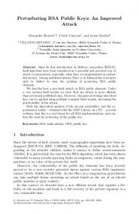
To improve the original NTW attack, we introduce a key P ranking procedure. The original NTW attack generates equations of the form i ai ki = {0, 1} where ki is a bit of the key and ai is either 0 or 1. The left part of the equation only depends on the feedback polynomials of the registers. The right part of the equation is either 0 or 1, determined by a voting system. The difference between the number of votes for 0 and 1 is denoted by |pv |. In the original attack, the equations are sorted by |pv | and the topmost equations are assumed to be correct. Using many equations results only in a small remaining key space which needs to be searched, but increases the probability that at least one equation is incorrect and the key is not found in the set of solutions of the linear equation system. To improve the attack, we first checked, with which probability the individual equations are correct. We ran 100 experiments against randomly chosen keys and counted in how many times the first, second, third... equation in A was correct. The results are shown in figure 1. The first 10 equations in A (see Section 3) are correct with a probability of at least 99%. This makes it highly unlikely that one of the first 10 equations is incorrect. Starting from equation 30, the probability that the equation is correct drops down to 70-60% for equation 55. This makes these equations only of minor use for the attack and one can assume that at least one of these equations is incorrect with high certainty. We decided to look for a strategy to generate highly likely sub key spaces in an order, so that the key spaces which are most likely to contain the correct key are generated first. The key spaces should still be described by a linear equation system and should contain many (at least 226 or more) keys, so that high parallel implementations which can search through such a key space as developed for the original attack can still be used, communication overhead is minimized and pipeline stalls due to too small key spaces are avoided. As a result, at most 36 equations from matrix A should be used. For the original NTW attack, it is never necessary to compute the success probability of an equation explicitly. Instead, one can just sort all equations by |pv |, assuming that equations with a higher difference have a higher success probability. We decided to compute the explicit probability for an equation from |pv |. First, one can simulate the attack against 100 random keys (using the same number of keystreams) and collect all generated equations with their voting difference and correctness. It is now possible to compute the success probability P (|pv |) of an equation using this data and a nearest neighbor smoother or similar methods (e.g. kernel smoother). We used a k-nearest-neighbor smoother for this paper.
6
Authors Suppressed Due to Excessive Length
Fig. 1. Success probabilities of the individual equations in matrix A
probability that equation is correct * 100
100
90
80
70
60 32768 keystreams 49152 keystreams 50 0
10
20
30 n’th equation in matrix A
40
50
We did not decide to compute the success probability for an equation from the line number in the matrix A and the number of keystreams. If a systematic problem in the keystream recovery method used would exist, this could decrease the success probability of some equations. Using |pv | for computing the success probability of each equation seems to be more appropriate. We can formulate our key ranking approach as a best-first-search over a directed graph: Assuming that we have a set of equations ei with respective individual success probabilities P (|pxi |) and that the success probabilities are independent, we can run a best-first-search for the correct key (if we use 64 equations) or for the most promising sub key space (if less than 64 equations are used). We assume that the set of possible keys or sub key spaces is a directed graph G = (V, E). A node v consists of a vector c that indicates which equation ei is correct (ci = 0) and which of the equations is incorrect Q (ci = 1). The probability that this node represents the correct sub key space is i (|ci − P (|pxi |)|). The node with the highest probability is the node with c = (0, . . . , 0) where all equations are assumed to be correct. An edge (v1 , v2 ) exists if v1 and v2 differ only in a single equation, which is assumed to be correct in v1 but assumed to be incorrect in v2 . We can now run a best-first search for the correct sub key space on this graph starting at the node with the highest success probability. Using 64 equations would guarantee that all keys are visited in the exact order of probability, however we think that the number of equations should be limited so that not too much time is spent for generating the keys to check and highly parallel hardware like CUDA graphics cards or FPGAs can be used in an efficient way. Using some kind of data structure for the queue in the best-first-search which allows inserts, searches and removals in O(log(n)) makes generating the sub key spaces
Title Suppressed Due to Excessive Length
7
very time efficient. However, memory consumption increases because up to m · g solutions need to be tracked in parallel, when m equations are used and g sub key spaces have been generated. 4.1
Performance results
Executing the old attack against 100 randomly chosen keys only resulted in 71% success rate with 215 keystreams available and 242 keys checked. Using our new key ranking method allowed us to recover the key in 90% of all tests, with also 242 keys checked in total. We used 35 instead of 22 equations, but checked the 8192 most likely sub key spaces. Figure 2 includes more details.
Fig. 2. Success rate of the improved attack
probability of success with 234 keys checked
100 90 80 70 60 50 40 30 20 10 old NTW attack new attack
0 0
8192
16384
24576
32768 40960 keystreams available
49152
57344
65536
Another advantage of our key ranking strategy is, that the attack time doesn’t need to be fixed at the beginning of the attack. Using just a single equation system has the disadvantage that all solutions are checked in an order not depending on their probability. Checking an equation system with 2n solutions will give the correct key after having checked 2n−1 solutions in average (if all equations in the system are correct). Using our approach makes it possible to start the attack with some reasonable parameters and then just wait for the correct key. If a lot of equations in A are correct, the correct key will be found much faster in average than with the original approach. If A contains a lot of incorrect equations, the attack will take longer, but one can decide to continue or cancel the attack at any point of time (assuming that enough main memory for the best-first-search is available). To speed up the final search through all generated sub key spaces, we present an FPGA implementation of the final search in the next part of this paper.
8
5
Authors Suppressed Due to Excessive Length
FPGA Implementation
FPGAs are very well-suited for an implementation of the final search phase of a sub key space. Linear Feedback Shift Registers form the main part of the DSC algorithm, and they can be implemented much more efficiently on an FPGA than on a CPU or GPU platform. 5.1
Basic Implementation Idea
Our improved DSC attack requires the knowledge of a valid reference (IV, Keystream) pair and an underdetermined equation system A·k =b
(1)
that constrains the key space. A and b are determined by the first part of the attack (see section 3), k denotes the cipher key. The FPGA design must iterate over all potentially valid cipher keys according to equation (1), compute the keystream and compare it to the reference keystream. Therefore, a cipher key generator, a DSC keystream generator and a compare unit comparing the keystream output to the reference keystream is necessary for the FPGA implementation. The design shall report cipher keys that produce an identical keystream as the reference. The most convincing way to implement the key generator is using a counter or full-cycle LFSR that generates “independent” bits and a combinatorial function generating “dependent” bits that use the “independent” bits as an input. The equation systems must be transformed beforehand for this purpose, such that the dependent bits are described as a function of the independent bits. The DSC keystream generator can be implemented straight-forward as described in [4]. 5.2
Optimizations
Optimizations are possible on several levels compared to a straight-forward implementation. A list of all matrices used for describing the optimizations is given in Table for clarity reasons. Simple Improvements: The key generator can be shared among several DSC units, as it generates one key per cycle whereas the compare units need multiple clock cycles for verifying one key. Unnecessary control signals may be removed and logic delays shall be kept short by inserting registers on critical paths. DSC Speedup: The fundamental DSC implementation as described in [4] requires three clock cycles per bit of keystream output. This can be reduced to one clock cycle by multiplexing and re-arranging the feedback taps. The corresponding feedback taps can be determined from the feedback matrices Rj2 and Rj3 . [1]
Title Suppressed Due to Excessive Length
9
Table 1. Matrices describing the Key Loading and the Equation System Matrix Dimension k 64 × 1 sk 128 × 1 ski,j len(Rj ) × 1 ck 128 × 1 iv 128 × 1 di 80 × 1 di,j len(Rj ) × 1 Rj len(Rj ) × len(Rj ) L 80 × 128 A0 128 × len(x) b0 128 × 1 x len(x) × 1
Description Cipher Key Session Key Vector that loads the i-th Bit of sk into Register j Zero-extended Cipher Key k Zero-extended Initialization Vector DSC State after i clocked in bits, without Output Combiner State of Rj after i clocked in bits Clock Matrix of Register j Load Matrix (Session Key to Initial State) Equation System Matrix Equation System Offset Vector Key Generator Counter Value
Key Loading: [4] suggests to load the session key in 128 clock cycles by clocking in one bit per cycle. This can be represented as iterating 128 times over the linear transformation di,j = Rj · di−1,j + ski,j for all four registers j, where d0 = (0, ..., 0) and ski,j is a vector with the size of register j in which the most significant position is set to bit i of the session key and all other positions are zero. The key can be loaded in one cycle by summarizing the four matrices R1,2,3,4 into one load matrix L such that d128 = L · sk
(2)
holds. A similar optimization is described in [1], but they only propose to load 16 bits per clock cycle. As a second step of improvement, the calculation of the full cipher key can be skipped: As described before, the “dependent” part of the cipher key is a combinational function of the “independent” cipher key bits. A matrix A0 and a vector b0 transforming an independent value x into the cipher key ck can be derived from A and b, such that the equation ck = A0 · x + b0
(3)
generates one key candidate compliant to equation (1) for each value of x. As the session key is the sum of cipher key and initialization vector, sk = ck + iv
(4)
the whole initial state can be expressed as a function of the independent cipher key bits by inserting equation (4) into equation (2) and then equation (2) into equation (3): 0 0 d128 = LA + iv) (5) | {z x} + L(b | {z } dynamic
static
10
Authors Suppressed Due to Excessive Length
Hard-Coding: Where the plain NTW attack proposed one equation system A · k = b, our key ranking allows us to reuse the matrix A and just invert one or more equations, i.e. modify b, if no key has been found for a particular sub key space. Hence, only the b vector needs to be loaded into the FPGA at run time, while A can be hard-coded into the design by a VHDL preprocessor. This saves hardware resources on the FPGA, reduces the complexity and eliminates potentially critical paths. The reference keystream can be hard-coded as well. Early Abort: A cipher key can be considered invalid as one bit from the generated keystream differs from the reference. In such a case, the comparison to the reference keystream can be aborted early such that the unit can immediately continue with the next key candidate. The probability that k subsequent bits of the keystream are correct for a wrong key is 2−k . On average, the comparison for a wrong key already fails after two keystream bits. Therefore, n − 2 cycles can be saved in comparison to a deterministic unit that always compares n bits. We compare at most 32 bits and thus save 30 cycles on average. Pre-Ciphering Pipeline: With the Early Abort optimization, several DSC units are competing to be loaded with a new initial state. As the arbitration logic complexity rises with the number of competing units, this number is to be kept low. A good way to do this is outsourcing the pre-ciphering phase into a strictly sequential, deterministic pipeline. With this optimization, the state after pre-ciphering is directly loaded into the computing DSC units. Input Buffering: Idle time of the FPGA has a negative impact on the effective performance. Therefore, an input buffer is used such that the PC can enqueue multiple tasks and the FPGA can immediately load the next task as soon as the previous one is finished. 5.3
Implementation
For our implementation, a Xilinx Spartan-3E 1200 (XC3S1200E) FPGA on a Digilent Nexys 2 board was used. The PC communication was implemented via the on-board RS-232 interface. Our final implementation includes all optimizations as described in section 5.2. The runtime of the design is not entirely deterministic, as – for a specific keystream – the position of the first failing comparison is unknown. Therefore, the key generator was given the ability to be paused, which is necessary when all available DSC units are busy. Figure 3 shows the structure of the key search unit, which forms the essential part of our hardware design. The dotted lines in the diagram denote the hardcoded data. The “State Offset” is sent to the FPGA at run time for each sub key space. It is determined by the attacked IV and the vector b0 .
Title Suppressed Due to Excessive Length
11
Fig. 3. Block Diagram of Key Search Unit counter value
grant
Arbiter req
/stall
Pre-Ciphering Pipeline
"State After Load" Logic
Counter/Full Cycle LFSR
Matrix A'
DSC Keystream Generator DSC Keystream Generator DSC Keystream Generator DSC Keystream Generator
Reference Keystream
Compare Unit
succ
FIFO din wr
Compare Unit 1
Compare Unit Compare Unit
dout rd empty
succ
State Offset
One pipelined key generator (see 5.2) was chosen to serve four DSC units – this is the maximum number implementable on one Look-Up Table. The key search unit consumes about 30% of the FPGA resources in total, such that three instances can be created on our device. This enables searching three sub key spaces at the same time. 5.4
Performance Evaluation
This section compares the performance achieved by our FPGA implementation with the CUDA performance published in [4]. We used five different, randomly generated equation systems for evaluating the maximum frequency by synthesizing the design for each of the equation systems. Table 2 shows the achieved results. Table 2. Performance Evaluation (using 232 equations) Max Frequency Performance [ keys ] Cost [U S$] Cost-Performance s FPGA 140 MHz 408.8 · 106 169 2.42 · 106 Ukeys S$·s 6 [4] CUDA / GTX 260 unknown 148 · 10 190 0.78 · 106 Ukeys S$·s
6
Summary
The final attack could be applied as follows: In the first phase of the attack, the adversary recovers keystreams by eavesdropping on a DECT call. If a phone is
12
Authors Suppressed Due to Excessive Length
used which displays a call duration counter that is implemented on the base station, the adversary might be able to recover about 5 known keystreams per second. After nearly two hours, the adversary has collected 215 known keystreams, which can be processed in the next phase of the attack. In the second phase of the attack, the adversary needs to generate frequency tables from the known keystreams. We did not modify this step in our paper. In the original attack, Nohl, Tews, and Weinmann used a SUN X4440 using 4 Quad-Core AMD Opteron CPUs running at 2.3 GHz to generate the tables in 20 minutes. This process is highly CPU bound, so that a single Opteron CPU could accomplish the task in about 80 minutes. Because this can be started while the first phase is still running, phases one and two need only two hours to complete. The runtime of these two phases is only affected by the rate of the keystream recovery process and the computing power available. In the third and last phase, the adversary uses the frequency tables generated in phase two to search for the correct key. He uses a PC which generates the most likely sub key spaces as described in Section 4 and transfers them to a single or multiple FPGAs connected via a serial line or other interfaces. The time for generating the sub key spaces is negligible compared to the time consumed by the FPGAs to check the sub key space, so that many FPGAs can be supplied by a single PC.
percentage of completed attacks at this time
Fig. 4. Time to completion of the attack using a single FPGA and 232 equations 100
80
60
40
20 using 32768 keystreams
0 1
10 100 time in minutes for the last phase of the attack (logscaled)
1000
Figure 4 shows the time to the completion of the last attack phase, using just a single Xilinx Spartan-3E 1200 (XC3S1200E) FPGA using 215 keystreams. About 20% of our experiments completed within one hour. The next 20% of our experiments needed up to one day to complete. The remaining 60% needed more than a day to complete. Please note that doubling the number of FPGAs used reduces the total time for the last phase by half and the attack scales almost perfectly when the number of available FPGAs is increased.
Title Suppressed Due to Excessive Length
13
References 1. Alcatel. Data ciphering device. U.S. Patent 5,608,802, 1994. 2. S. Lucks, A. Schuler, E. Tews, R.P. Weinmann, and M. Wenzel. Attacks on the DECT authentication mechanisms. Topics in Cryptology–CT-RSA 2009, pages 48– 65. 3. H.G. Molter, K. Ogata, E. Tews, and R.P. Weinmann. An Efficient FPGA Implementation for an DECT Brute-Force Attacking Scenario. In 2009 Fifth International Conference on Wireless and Mobile Communications, pages 82–86. IEEE, 2009. 4. K. Nohl, E. Tews, and R.P. Weinmann. Cryptanalysis of the DECT Standard Cipher. Feb 2010.