fragility curve development for these applications is also the same as that used in the detailed analysis of bridge structures and the seismic performance of.
Fragility Curve Development for Assessing the Seismic Vulnerability of Highway Bridges by John B. Mander, University at Buffalo, State University of New York
Research Objectives The principal objective of this research is to develop, from the fundamentals of mechanics and dynamics, the theoretical basis of establishing fragility curves for highway bridges through the use of rapid analysis procedures. In contrast to other methods that have been used in the past, such as either empirical/experiential fragility curves or individualized fragility curves based on extensive computational simulations, the present approach seeks to establish dependable fragility curves based on the limited data readily obtainable from the National Bridge Inventory (NBI).
Sponsors MCEER Highway Project/FHWA National Institute of Building Sciences (NIBS)
Collaborative Partners Retrofitting Manual
T
he purpose of this research is to set forth the basis for developing fragility curves that can be used in various ways as part of a seismic vulnerability analysis methodology for highway bridges. To develop a set of fragility curves for various damage states for a specific bridge, the notion of adjusting “Standard Bridge” fragility curves for sitespecific effects is adopted. Only three sources of data are needed for this analysis: (1) National Bridge Inventory (NBI) records that contain the bridge attributes and geographical location; (2) ground motion data (this is best obtained from the USGS web site); and (3) geological maps from which soil types and hence S-factors can be inferred. Full details of this approach are given in Basöz and Mander (1999).
Ian Buckle, University of Auckland Anindya Dutta, EQE International, formerly of the University at Buffalo Gokhan Pekcan, University at Buffalo Andrei Reinhorn, University at Buffalo Stuart Werner, Seismic Systems and Engineering Consultants
HAZUS Developments Nesrin Basöz, K2 Technologies Michael O’Rourke, Rensselaer Polytechnic Institute
1
Links to Current Research Retrofitting Manual for Highway Systems • Volume I is concerned with network analysis and requires the use of bridge specific fragility curves to assess the direct and indirect losses as a result of earthquake-induced damage to bridges (Werner et al., 1998; 1999). It is important that a rapid analysis procedure is available to minimize the computational effort and data collection requirements. • Volume II is concerned with the seismic evaluation and retrofitting measures for bridge structures. In order to assess the seismic vulnerability of a suite of bridges, “rapid screening” techniques are used. As an alternative to using indexing methods, similar to the multiplicity of existing approaches used currently by various states and the present retrofitting manual, the proposed fragility curve based method for the rapid screening of highway bridges is consistent with the network analysis used in Volume I and the detailed analysis of Volume II. • The underlying theory that forms the basis of the fragility curve development for these applications is also the same as that used in the detailed analysis of bridge structures and the seismic performance of individual components and members. These detailed procedures are described in Volume II.
2
The Approach Using “Standard Bridge” Fragility Curves Fragility Curve Theory For a given bridge, it is possible to predict, deterministically, the level of ground shaking necessary to achieve a target level of response and/or damage state. In addition to assuming material properties and certain other structural attributes that affect the overall capacity of a bridge, such a deterministic assessment requires that certain assumptions be made about the ground motion and site conditions—both factors that affect seismic demand. Naturally, values of these parameters are not exact—they invariably have a measure of both randomness and uncertainty associated with them. An increasingly popular way
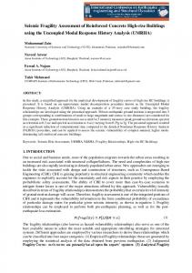
of characterizing the probabilistic nature of the phenomena concerned is through the use of socalled fragility curves. Figure 1 shows how the inherent uncertainty and randomness of bridge capacity versus ground motion demand can be used to establish fragility curves. Figure 1(a) shows an acceleration-displacement spectra for the ground motion. Superimposed with this curve is the pushover capacity of a bridge. In a deterministic analysis, the intersection of the two curves gives the expected level of performance. However, probability distributions are drawn over both the capacity and demand curves to indicate the associated uncertainty and randomness of performance. From this figure it is evident there is a wide range of possible performance outcomes—there is not a unique or exact answer.
It is anticipated that planning engineers in State and Federal government may use network analysis software that has been developed as part of Volume I of a three-volume set of Retrofitting Manuals under the MCEER Highway Project (see Seismic Retrofitting Manual for Highway Systems in this report). This software will contain fragility curves for bridges developed as part of this research. Bridge engineers in State departments of transportation use “rapid screening” techniques for assessing the seismic vulnerability of bridges as a planning/scheduling tool. The new approach is expected to use the fragility curve methodology developed herein. Engineers, social scientists and planners use the FEMA-NIBS software HAZUS, which is to contain a new fragility curve procedure developed as part of this research. State departments of transportation and their engineering consultants are expected to use detailed seismic evaluation procedures as part of their retrofitting design studies. The underlying theory that forms the basis of the fragility curve development is also the same as that used in the detailed analysis of bridge structures and the seismic performance of individual components and members.
(1)
where ⌽ is the standard log-normal cumulative distribution function; Sa is the spectral acceleration amplitude (for a period of T = 1 sec.); Ai is the median (or expected value) spectral acceleration necessary to cause the ith damage state to occur; and c is the normalized composite log-normal standard deviation which incorporates aspects of uncertainty and randomness for both capacity and demand. The latter parameter is sometimes loosely referred to as either the coefficient of variation or the coefficient of dispersion. The parameter has been calibrated by Pekcan (1998), Dutta and Mander (1998) and Dutta (1999) from a theoretical perspective, and validated by Basöz and Mander (1999) against experiential fragility curves obtained from data gathered from the 1994 Northridge and 1989 Loma Prieta earthquakes by Basöz and Kiremidjian (1998).
Spectral Acceleration
1 S F (S a ) = ⌽ ln a c Ai
Based on these investigations it is recommended that c = 0.6. Median values of the peak ground acceleration for five different damage states are assessed using an algorithm that is based on the socalled capacity-spectrum method, as indicated in Figure 1(a). This displacement-based nonlinear static analysis procedure assumes a standard AASHTO-like earthquake response spectrum shape, which can be adjusted later to account for site-specific spectral ordinates and/ or soil types. The five damage states and their associated performance outcomes are listed in Table 1.
Links to Current Research (cont.)
(cont.)
HAZUS Developments • The HAZUS project, which is sponsored by FEMA through a contract with NIBS, is using the results of this research to develop software for the secondgeneration of fragility curves for highway bridges. This is part of the first major revision of HAZUS and is included in the HAZUS98 software (refer also to HAZUS, 1997).
Median Demand
Median Capacity
Spectral Displacement
(a) Capacity-Demand Acceleration-Displacement Spectra Showing Randomness and/or Uncertainty in Structural Behavior and Ground Motion Response 1
Cumulative Probability
If structural capacity and seismic demand are random variables that roughly conform to either a normal or log-normal distribution then, following the central limit theorem, it can be shown that the composite performance outcome will be lognormally distributed. Therefore, the probabilistic distribution is expressed in the form of a so-called fragility curve given by a log-normal cumulative probability density function. Fortunately, only two parameters are needed to define such a curve—a median (the 50th percentile) and a normalized logarithmic standard deviation. Figure 1(b) presents the form of a normalized fragility curve for bridges. The cumulative probability function is given by:
0.5
0 0
1
2
3
Spectral Acceleration Ratio
Sa /Ai
(b) Normalized fragility curve that accounts for uncertainty and randomness in both demand and capacity. Note c = 0.6. ■ Figure 1.
Probabilistic Definition of Uncertainty/Randomness in Establishing Fragility Curves for a Seismic Vulnerability Analysis
Fragility Curve Development
3
■ Table 1.
Definition of Damage States and Performance Outcomes
Damage Descriptor for Post-earthquake Repairs Required State Degree of Damage Utility of Structure 1
None (pre-yield)
Normal
None
--
2
Minor/Slight
Slight damage
Inspect, adjust, patching
= dsi | PGA]
P[D > = dsi | PGA]
Time of Outage Expected
0.7 0.6 0.5 0.4 0.3
0.7 0.6 0.5 0.4 0.3 0.2
0.2
0.1
0.1
PGA (g)
0 0 0.1 0.2 0.3 0.4 0.5 0.6 0.7 0.8 0.9 1.0 1.1 1.2 1.3 1.4 USGS-moderate WCFS-moderate
moderate - analytical Loma Prieta minor & moderate
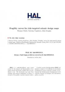
(a) Moderate damage, DS3 ■ Figure 2.
0
PGA (g) 0 0.1 0.2 0.3 0.4 0.5 0.6 0.7 0.8 0.9 1.0 1.1 1.2 1.3 1.4 USGS major
major analytical
WCFS major
(b) Major damage, DS4
Comparison of Analytical and Empirical Fragility Curves for Discontinuous Multiple Span Bridges with Single Column Bents and Non-monolithic Abutments
4
Validation of Theory with Empirical Evidence Analytically predicted fragility curves for various different bridge types were validated against fragility curves that were empirically derived from data gathered for highway bridges damaged in the 1994 Northridge and 1989 Loma Prieta earthquakes. A sample of the validation for one common class of California bridge is given in Figure 2. In spite of the large degree of uncertainty in defining both bridge damage and the spatial distribution of ground motion in the field, it will be noted that both the median damage values (50 percentile) and the shape (for c = 0.6) of the fragility curves agree rather well.
Implementation and Database Requirements The National Bridge Inventory (NBI) is a database maintained by the Federal Highway Administration that contains information on every highway bridge in the U.S. The database has 116 fields that are used to describe structural and operational characteristics of a bridge. Because all the nation’s highway bridges are required to be inspected on a biennial basis, the NBI database is kept up to date. Information in the NBI provides functional and operational characteristics, but there is insufficient detail to permit a detailed analysis to be performed when deriving fragility curves. Therefore, the basis of obtaining a bridge specific fragility curve is to take the results of a “standard bridge”fragility curve and to scale those results using selected data from the NBI.
A “standard bridge” is assumed to be a “long” structure with no appreciable three-dimensional (3D) effects present. For several types of “standard bridges,” median PGA values have been derived for each of the damage states (a2, a3, a4, a5). The results of the “standard bridge” are then modified by factors accounting for skew (Kskew) and 3D effects (K3D) using the NBI database described in Table 2. This table shows which fields of the NBI are used and for what purpose.
“Standard Bridge” Fragility Curves
• Structure Fragility Examination and Upgrading of ATC-13, A. Cakmak, Princeton University
• Lateral Strength Analysis Methods, R. Imbsen, Imbsen Associates, Inc.
• Risk Assessment of Highway Systems, S. Werner, Seismic Systems and Engineering Consultants
• Seismic Risk Analysis of
The “standard bridge” fragility curves are presented in Table 3 where median fragility parameters are listed for conventionally (nonseismically) designed and seismically designed bridges. Implicit in the median fragility curve values are assumptions which are considered to be in keeping with typical construction practice throughout the U.S.
Scaling the “Standard Bridge” Fragility Curves to Account for Skew and 3D Effects In order to convert the “standard bridge” fragility curves to a bridge– specific value for a given spectral acceleration, the parameters Kskew and K 3D are used as scaling relations. The effect of bridge skew on changing fragility curves can be accounted for by applying the angle of skew given in the NBI (␣skew) using: K skew = sin ␣skew
Related Highway Project Tasks
Bridges in Memphis, H. Hwang, Center for Earthquake Research and Information, University of Memphis
• Evaluation of Bridge Damage Data from Recent Earthquakes, A. Kiremidjian, Stanford University
• SRA Validation and Fragility Curves, M. Shinozuka, University of Southern California and G. Deodatis, Princeton University
• Major Bridge Damage State Modeling, W.D. Liu, Imbsen Associates, Inc.
(2)
Fragility Curve Development
5
■ Table 3.
U.S. Highway Bridge Fragility Curve Median Values of PGA Median PGA
Classification
NBI Class
Damage State
Conventionally Designed Bridges
Seismically Designed
Non-California
California
0.26 0.35 0.44 0.65
0.33 0.46 0.56 0.83
0.45 0.76 1.05 1.53 0.54 0.88 1.22 1.45
Multi-column bents, simply-supported
101-106 301-306 501-506
2 3 4 5
Single column bents, box girders, discontinuous
205-206 605-606
2 3 4 5
not applicable
0.35 0.42 0.50 0.74
Continuous concrete
201-206 601-607
2 3 4 5
0.60* 0.79 1.05 1.38
0.60* 0.79 1.05 1.38
0.91* 0.91 1.05 1.38
402-410
2 3 4 5
0.76* 0.76 0.76 1.04
0.76* 0.76 0.76 1.04
0.91* 0.91 1.05 1.38
Al l
2 3 4 5
0.8* 0.9 1.1 1.6
0.8* 0.9 1.1 1.6
0.8* 0.9 1.1 1.6
2 3 4 5
0.4 0.5 0.6 0.8
0.4 0.5 0.6 0.8
0.6 0.8 1.0 1.6
Continuous steel
Single span
Major bridges
* Short period portion of spectra applies, therefore evaluate Kshape.
■ Table 4.
Modification Rules Used to Model 3D Effects NBI Class
K3D Conventional Design
K3D Seismic Design Year > 1990 (> 1975 in CA)
Concrete
101-106
1 + 0.25/np
1 + 0.25/np
Concrete Continuous
201-206
1 + 0.33/n
1 + 0.33/np
Steel
301-310
1 + 0.09/np ; L ≥ 20 m 1 + 0.20/np ; L < 20 m
1 + 0.25/np
Steel Continuous
402-410
1 + 0.05/n ; L ≥ 20 m 1 + 0.10/n ; L < 20 m
1 + 0.33/np
Prestressed Concrete
501-506
1 + 0.25/np
1 + 0.25/np
Prestressed Concrete Continuous
601-607
1 + 0.33/n
1 + 0.33/np
Type
n = number of spans in bridge; np = n - 1 = number of piers
6
Table 4 presents modification rules to account for 3D effects via the parameter K3D. This parameter converts a long “standard bridge” structure to a specific (straight/right) bridge with a finite number of spans.
■
Table 5. Modified Repair Cost Ratio for All Bridges Damage State
1: No damage (pre-yield) 2: Slight damage
0.08
0.02 to 0.15
0.25
0.10 to 0.40
See Equation 6
0.30 to 1.0
5: Complete
(3)
where a i is the median spectral acceleration (for T = 1.0 second spectral ordinate) for the ith damage state listed in Table 3; S is the soil amplification factor for the long period range, that is the 1.0 second period amplification factor, Fv, given by NEHRP (note S = 1 for rock sites was assumed in deriving the “standard bridge” fragility curves).
Scaling Relations for Damage State 2 For slight damage, the median fragility curve parameter is given by the following equation: (4)
where a2 is the PGA level given in table 3; S is the soil amplification factor; and Kshape is defined by the following equation: Kshape = 2.5Cv /Ca
0 0.01 to 0.03
3: Moderate damage
The modified median fragility curve parameter is given by
A2 = Kshape a2/S
0 0.03
4: Extensive damage
Scaling Relations for Damage States 3, 4, and 5
Ai = Kskew K3D ai /S
Best Mean Range of Repair Cost Ratio Repair Cost Ratios
(5)
In Equation (5), the factor 2.5 is the ratio between the spectral amplitude at 1.0 second (Ca) and 0.3 seconds (Cv) for the standard codebased spectral shape for which the
“standard bridge” fragility curves were derived. This equation is necessary to ensure all fragility curves possess a common format— either PGA or Sa at T = 1.0 second. Note that where the PGA level given in Table 3 is identified with an *, the short period motion governs, K shape ≤ 1, and the soil amplification factor for “short” period structures (provided by NEHRP) is used. Otherwise, Kshape = 1. Note that in Equation (4) there is no modification assumed for skew and 3D effects. The structural displacements that occur for this damage state are assumed to be small (generally less than 50 mm), thus the 3D arching effect is not engaged since the deck joint gaps do not close.
Direct Economic Losses Based on the work of Mander and Basöz (1999), the damage ratios listed in Table 5 can be used to estimate the extent of damage expected as a result of an earthquake. The best mean repair cost ratio for “complete” damage—that is RCRi=5 for damage state 5—is defined as a function of number of spans as given below: RCRi=5 = 2 n ;
≤ 1.0
(6)
Fragility Curve Development
7
where n is the number of spans in the main portion of the bridge. In this equation, it is assumed that the most common failure mechanism will result in unseating of, at most, two spans simultaneously. The total repair cost ratio—that is the expected proportion of the total replacement cost of the entire bridge resulting from earthquake damage, or the direct loss probability—is defined as follows:
∑ (RCR ⋅ P[DS | S ]) < 1.0 5
RCRT =
i
i =2
i
a
(7)
[
]
where P DS i | S a is the probability of being in damage state DSi for a given spectral acceleration, Sa, for a structural period of T = 1.0 seconds; and ■ Table 6. Bridge Data Necessary for the Example Analysis RCR i is the NBI Field Data Remarks repair cost ratio for the 27 1968 Year built i th damage 34 58 Angle of skew mode. If this 43 501 Prestressed concrete, simple span total repair 45 3 Number of spans cost ratio is multiplied 48 23 Maximum span length (m) by the re49 56 Total bridge length (m) placement 52 10 Bridge width (m) cost of the
0.9
Consider a three-span simply supported prestressed concrete bridge located in the Memphis area on very dense soil and soft rock (site class C). Table 6 lists the data for this bridge obtained from NBI. The following ground motion data is assumed for a scenario earthquake: Sa(T = 0.3 sec) = 1.4 g, (S = 1.0); Sa(T = 1.0 sec) = 0.28 g, (S = 1.52); and A = 0.35 g.
Solution Since the bridge was constructed in 1968 and is located outside of California, the first and the fifth rows of Table 3 apply, respectively, thus for type 501: a2 = 0.26 g; a3 = 0.35 g; a4 = 0.44 g; and a5 = 0.65 g. Note that no * is used for a2; this implies “long periods” always govern, therefore Kshape = 1. 0.25 0.25 = 1+ = 1.125; n −1 3−1
K skew = sin ␣ = sin 58 = 0.92
0.8
P[D > = dsi | Sa]
Illustrative Example Problem
K3 D = 1 +
1
(8)
0.7 0.6
minor-analytical moderate-analytical
0.5
major-analytical 0.4
collapse-analytical
0.3 0.2 0.1 0 0
0.2
0.4
0.6
0.8
1
1.2
1.4
Spectral Acceleration (g)
■ Figure 3.
Fragility Curves for the Example Prestressed Concrete Bridge with Simply Supported Girders
8
bridge, the expected direct monetar y dollar loss can be assessed. Work on this aspect is ongoing.
From Equation (4) A2 = 0.17, and Equation (3) Ai = 0.681ai, thus: A3 = 0.24 g; A4 = 0.30 g; and A5 = 0.44 g. As shown in Figure 3, the probability of being in a given damage state, when Sa (T = 1 sec) = 0.28␣ g, is given in Table 7. This table also presents the repair cost ratios from which the expected loss ratios are determined in terms of the total
■ Table 7.
Analysis of Direct Loss Probability P[D>DSi | Sa ]
P[DSi | Sa ]
RCRi
Product
(2)
(3)
(4)
(3) X (4)
1
1
0.203
0.00
0.00000
2
0.797
0.196
0.03
0.00588
3
0.601
0.147
0.08
0.01176
4
0.454
0.228
0.25
0.05700
5
0.226
0.226
0.67
0.15142
1.000
RCRT =
0.226
i (1)
Total probabilities:
replacement cost for the entire bridge. From Table 7, the total loss ratio is RCRT␣ =␣ 0.226.
Conclusions and Future Work Previous editions of the seismic retrofitting manual have used an indexing method as part of the screening approach. Indeed there are many such methods available that have been used by various state/owner agencies. The method presented herein, however, is a new development. It is the same method that is used in Volume I of the new Manual that is concerned with the post-earthquake integrity of an entire highway system. The method has also been adopted as the future approach for defining fragility curves in HAZUS. The fragility curve-based rapid screening method is consistent with the detailed seismic evaluation approach adopted as it is derived from the same theoretical basis that is founded upon the fundamentals of
mechanics. However, where the rapid screening and detailed approaches differ is in the extent of data gathering, and time and effort necessary to perform a seismic vulnerability analysis. The rapid screening approach operates on limited data as it is intended for evaluating a suite of bridges and ranking them in order of seismic vulnerability. On the other hand, a detailed analysis is intended to be a more exacting assessment of individual bridges and the vulnerability of individual components. In the future, it is intended to extend the loss estimation ratios to include direct and indirect losses in dollar terms. Direct losses arise from damage to the bridge structure itself, whereas indirect losses may arise as a result of collapse resulting in the loss of life and limb. These parameters can be used as a basis for sorting and assigning retrofit/repair/rehabilitation priorities. The choice of sorting strategy can be left to the value-system that is adopted by the owning agency and/or underwriting authority.
Fragility Curve Development
9
References Basöz, N. and Kiremidjian,A.S., (1998), Evaluation of Bridge Damage Data from the Loma Prieta and Northridge, CA Earthquakes, Technical Report MCEER-98-0004, Multidisciplinary Center for Earthquake Engineering Research, Buffalo, New York. Basöz, N. and Mander, J.B., (1999), Enhancement of the Highway Transportation Lifeline Module in HAZUS, Final Pre-Publication Draft (#7) prepared for the National Institute of Building Sciences, March 31, 1999. Dutta, A., (1999), On Energy-Based Seismic Analysis and Design of Highway Bridges, Ph.D. Dissertation, Science and Engineering Library, University at Buffalo, State University of New York, Buffalo, New York. Dutta,A. and Mander, J.B., (1998), “Seismic Fragility Analysis of Highway Bridges,” INCEDEMCEER Center-to-Center Workshop on Earthquake Engineering Frontiers in Transportation Systems,Tokyo, Japan, June. HAZUS, (1997), Earthquake Loss Estimation Methodology, Technical Manual, National Institute of Building Sciences for the Federal Emergency Management Agency. Pekcan, G., (1998), Design of Seismic Energy Dissipation Systems for Concrete and Steel Structures, Ph.D. Dissertation, University at Buffalo, State University of New York, Buffalo, New York. Werner, S.D.,Taylor, C.E., Moore, J.E., Jr., Mander, J.B., Jernigan, J.B. and Hwang, H.M., (1998), “New Developments in Seismic Risk Analysis Highway Systems,” 30th UJNR Panel Meeting on Wind and Seismic Effects, Gaithersburg, Maryland. Werner, S.D., Taylor, C.E., Moore, J.E. and Walton, J.S., (1999), Seismic Retrofitting Manuals for Highway Systems, Volume I, Seismic Risk Analysis of Highway Systems, and Technical Report for Volume I, Multidisciplinary Center for Earthquake Engineering Research, Buffalo, New York.
Continue with next chapter
10