fragmentation and heave in the blasting process is due to the effects of the high pressure gas generated by the explosive in the ... phonons in order to model the ground vibration due to ..... It can be clearly seen that the predicted crack.
Fragmentation and heave modelling using a coupled discrete element gas flow code Alan Minchinton ICI Explosives, Technical Centre, Kurri Kurri, Australia 2327
Peter M. Lynch ICI Explosives, Wilton Centre, Middlesbrough, UK TS90 8JE
ABSTRACT: Experimental evidence indicates that a large percentage of the crack development and subsequent fragmentation and heave in the blasting process is due to the effects of the high pressure gas generated by the explosive in the blasthole. An explicit finite/discrete element code has been developed to dynamically model stress field development, crack generation and crack growth as well as the motion and stacking of the rock fragments. Cracking in the current model is limited to failure under tension (Rankine). This failure is due to both the stress and the gas flow which is treated by coupling the discrete element porosity field to a finite volume gas flow model. Several examples are discussed which show striking qualitative differences between blasting with stemming to contain the gases in the blastholes, and without stemming.
1
INTRODUCTION
The development of a tractable computer based model to describe the entire blasting process from detonation to “rock on the ground” has been an endeavour that has only become partly possible in recent times due to the accessibility of affordable computing resources. To the authors’ knowledge a single code that can dynamically model the full three dimensional aspects of even a one hole blast by using a realistic mechanistic approach does not exist and there are very few codes that have been developed to tackle this complicated problem even in two dimensions. A complete mechanistic simulation of a particular process would include simulations of all the known underlying physical events that contribute to that process. Naturally, the type of approach adopted must match the desired outcome; for example, there is little point in considering crystal lattice vibrations and phonons in order to model the ground vibration due to a large blast. A truly mechanistic blasting model must include simulations of a series of macroscopic processes which work in concert. The overall model must include a description of detonation or some other high pressure– producing process that causes high amplitude stress waves to emanate from the blasthole wall into the rock fabric. There must be a model to track the stress/strain
behaviour of the rock including the effects of insitu stresses and a model that considers crack initiation, propagation and interaction with other cracks and existing geological features as well as a model that allows for cracking processes due to the high pressure gases produced in the blasthole. There should also be a dynamic model for the bulk motion of the fragmented rocks allowing for contact and settling. These processes should evolve dynamically and for multi–hole blasts the code should be capable of considering the effects of timing and blast geometry. 1.1
The importance of stress and gas
Until the early 1980’s there were two schools of thought regarding the theories of rock fragmentation by blasting (Winzer & Ritter 1985). Differences centred on the relative importance of either the stress field or the high pressure gases to cracking and fragmentation. Although it was actually realised much earlier (Kutter & Fairhurst 1971; Fourney et al. 1983) that each process plays an important rˆole the issue was not clearly resolved experimentally. Reduced scale blasting tests carried out by Winzer and Ritter (1985) and Gur et al. (1984) identified the fact that the initial cracks at a free surface were caused by the tensile stresses resulting from the reflection of the p–wave as it travels back to the blasthole and were
not due to cracks radiating from the blasthole as originally thought. Persson (1990) however, claims that these reflected tensile waves carry insufficient energy to cause damage, they simply promote the growth of the dominant radial cracks already emanating from around the blasthole. Winzer and Ritter (1985) also claimed that the bulk of the fragmentation was due to longer term stress wave effects rather than the blasthole gases [which had vented]. Persson (1990) asserts that the blasthole gases act on the wedges of rock formed by the radial cracks between the blasthole and the free face resulting in bending stresses in the wedges that lead to fragmentation initiated mainly at existing joints, cracks and flaws. Haghighi et al. (1988) reported results conducted by Britton in the early eighties that described measurements of gas pressures and relationships between the gas pressure and the work done on the rock mass for a range of decoupling ratios. It was found that the shock energy played an insignificant rˆole especially for decoupled charges. Britton (1987) also showed the importance of dilatancy or volume strain induced by simple shear as an important bulking mechanism. Haghighi et al. (1988) also developed a finite element model of a single blasthole bench geometry that incorporated several predefined radial vertical cracks which could be pressurised to different lengths. The results showed that beam bending and gas pressurisation were more important processes for rock breakage than shock or vibrational processes. Their results also showed that maximum displacements were achieved by allowing only the first two thirds of the cracks to be pressurised in the radial direction toward the free face. In a series of computations and experiments involving steel lined and unlined blastholes in perspex McHugh (1983) clearly showed several important features: (a) short radial cracks due to the circumferential tensile stresses alone are generated close to the blasthole, (b) the primary effect of the explosive gases is to cause the crack length to increase by a factor of five to ten, (c) a secondary effect is a 50% increase in the number of small fractures, (d) in direct comparison with Winzer and Ritter’s (1985) findings the gas acts dynamically and cooperatively with the stress field to produce cracks and, (e) the gases penetrate the cracks and reach the crack tip i.e. the gas pressurisation of the cracks causes the large crack extensions. Similar comprehensive experiments were carried out by Brinkmann (1987, 1990) using unstemmed blastholes that were either unlined, or lined with alumini-
um or steel in a typical gold mine stoping environment. Brinkmann concluded that (a) initial fracturing close to the blasthole is caused by the shock loading and (b) fragmentation due to the action of the stress field alone is limited. With the lined blastholes the fragmentation was only 10% of that produced with the unlined blastholes. Similarly the heave velocities were reduced by a factor of between five and eight. These results clearly showed the dominance of the gas effects in producing both fragmentation and heave. 1.2
Blasting related codes and models
There have been several attempts to develop codes which consider some or all of the dominant blasting processes. It is not the intention of this paper to review the field, but some of the more relevant codes or models which deal with cracking, fragmentation and the effects of the gas in particular are discussed briefly. We are not concerned here with “engineering” codes like SABReX (Jorgenson & Chung 1987) and EXEN (Sarma 1994) since they are highly empirical and are neither dynamic nor truly mechanistic in the sense defined here. FDM (Yang & Wang 1995) is a constitutive model that has been implemented in the finite element code PRONTO (Taylor & Flanagan 1987). This model has had an extended history and is based on the modified Sandia (Kipp & Grady 1979; Kuszmaul 1987) microcrack damage model. In FDM the damage is determined by the fractal dimensions for joints and cracks. BFRACT (Simons et al. 1995) is a constitutive model that has been implemented in the finite element code DYNA2D (Hallquist 1982). It is a multiplane model capable of considering the heterogeneity of geologic materials and uses a fracture mechanics based stress intensity factor formulation with a viscous crack growth law in which the crack velocity is limited by a function of the shear velocity. CAVS (Barbour et al. 1985) was developed as a 3D finite element constitutive model of tensile fracture initiation and growth. The porosity and permeability of the cracks were derived from the void strain due to crack opening and closing. Crack planes form normal to the principal tensile stress direction with the transient, laminar, viscous fluid flow being driven by crack segment pressure gradients providing a constant pressurisation over any given fracture segment. Taylor and Preece (1989) have developed an elegant two dimensional distinct element code DMC in which the elements are disks derived from the cross–
section of spheres, mainly for modelling the motion associated with blasting layered rock masses. The code does not model the fragmentation process at al l but does employ a porosity based gas flow model (Preece 1993) and explosive blasthole loading based on non–ideal detonation. PFC3D (Itasca 1995) is a three dimensional particle flow code in which an impermeable rock mass is modelled by aggregated sphere based distinct elements with soft contacts and compressive, shear and tensile contact “bond” breakage mechanisms. The dynamically coupled fluid “flow” is associated with penny shaped overlapping reservoirs produced at these “crack” locations interconnected via a pipe network of rectangular cross section. A study of fracturing in microscopic random assemblies of dislocations has recently been carried out by Napier and Peirce (1995). They used the displacement discontinuity boundary element method which simulates distinct element processes for inertial systems that are strongly damped and that have small inelastic strains on individual discontinuities. The crack growth can extend from the nucleation sites according to specified growth rules. Song and Kim (1995) have developed a Dynamic Lattice Network Model in which the rock mass is discretised into triangular elements which have particles situated at each vertex and massless springs connecting them. The mass of the particles is determined from the density and the heterogeneous spring constants are determined from the experimental range of the rock strength tests. A blasthole pressure profile is applied using a function that represents both the high strain component and the gas pressurisation phase. The creation and propagation of cracks is associated with the failure of the lattice springs. Munjiza and co–workers (Munjiza 1992; Owen et al. 1992) developed a combined finite element – discrete element code that employs a simple fracture based softening Rankine plasticity model to generate cracks and a sophisticated contact detection scheme for handling the fragments. The interaction between the rock and detonation gas is handled using a dual discretisation technique. 2
MBM2D: MECHANISTIC BLASTING MODEL
The challenge to develop a single computational model that is capable of dynamically modelling all the blasting processes mentioned in Section 1 in a realistic mechanistic fashion has only been achieved by one code to date, namely MBM2D (for Mechanistic Blasting
Model). This code is an explicit finite element – discrete element code which has evolved from further work of Munjiza and co–workers (Munjiza 1992; Owen et al. 1992) and the present authors over the past two years and is an extension of the ELFEN package (Rockfield Software) which among other things adds pre and post processing capabilities. The discrete element part of the code is currently restricted to two dimensional problems using plane strain or axisymmetric elements but the main thrust of current developments is towards the three dimensional version. 2.1
Finite elements
In the regular two dimensional finite element technique the problem domain R2 is mapped to the computational domain C 2 as a series of polygonal elements fei g joined at nodes. Various types of elements have been used ranging from triangular to eight node quadrilaterals. We use triangular elements as the larger elements are computationally expensive and it is now generally accepted that with adequately fine meshing the triangular elements are more efficient and just as accurate. As an example, Figure 1 shows the radial displacement at the point (4.96, 5.04) in an axisymmetric half space measuring 10 m x 20 m. A triangular mesh was used with 9664 elements and 4942 nodes. The purely elastic material with density 2500 kg/m3 had a p–wave velocity of 2500 m/s and a Poisson’s ratio of 0.25. The signal was produced by a travelling pressure loading of the form,
P = Po tne bt where n = 6, b = 5000 and Po was 1 MPa applied
on the line from (0.1,0.0) to (0.1,5.0) to replicate a velocity of detonation of 5500 m/s. The bottom and right boundaries were non–reflecting. The sampling interval was 50 �s and the output was not smoothed or altered. There is no noise in this signal and the filtering effects of the mesh are negligible; the signal was not altered by halving the number of elements. Various boundary conditions or constraints can be applied to C 2 to simulate R2; single nodes or a series of nodes constituting a line or surface can be constrained to move only in certain ways, for example, damping on certain exterior lines to prevent the reflection of waves back into the mesh (non–reflecting boundaries). Similarly, loads can be applied to C 2 , for example a pressure or face load might be applied to a series of nodes to simulate an impulse.
2•10-7
required for a system in which an unknown number of elements is created throughout the simulation.
1•10-7
Amplitude
2.3 0 -1•10-7 -2•10-7 -3•10-7 0
2
4 6 Time (ms)
8
10
Fig. 1: The radial displacement at an interior point in an axisymmetric half space. Details are given in the text.
In essence then, an explicit finite element code solves for the nodal displacements over fei g in C 2 using spatial and temporal integration. The manner in which the nodes respond and move is determined by the material properties assigned to the related elements. For example if R2 is a purely elastic material then the stresses and strains generated throughout C 2 due to the nodal displacements will be determined by the simple tensor based elasticity equations (Timoshenko & Goodier 1970). 2.2
Discrete elements
In this code a two dimensional discrete element dj is a separate, distinct polygonal element made up of a collection of finite elements (at least one). Since the discrete elements are deformable a critical state of stress or strain can be reached where an element separates or fractures into two or more discrete elements or their boundaries can change if the fracture is only partial. This is different from the techniques used in the codes �DEC and 3DEC attributed to Cundall (Cundall 1980; Cundall & Hart 1988) which use two types of elements, one that is not discretised at all and is “simply deformable” and another type that is “fully deformable” and is discretised into finite difference zones. Neither of these element types can fracture. Elaborate techniques have been devised to minimise the computational effort spent on contact detection i.e. establishing which elements, within the set fdj g are in contact with the currently inspected element, and on the evaluation of contact forces (Owen et al. 1992). There is also an elaborate “book keeping” system associated with the memory management
Fracturing
We do not model the actual crack tip as is often done with codes that consider single crack propagation. It is common knowledge though that the speed of a moving crack is limited only by the rate at which stored elastic energy is relieved from the crack tip i.e. by the free fracture surface elastic wave velocity, the Rayleigh wave speed cR . Experimental crack speeds are typically one third to one half cR and recent theory (Ching 1994) suggests that steady state crack propagation above a critical speed of about 0:34cR may be unstable. Fracturing in the code is based on a fracture based softening Rankine plasticity model (Figure 2). In each element the fracture criterion is checked for at every timestep. Fracturing may occur within a finite element if the tensile strength of the rock has been reached and if in the post peak process the stress has reduced to zero following the local softening gradient:
�t2 qA (2.1) i 2Gf where �t is the tensile strength, Gf is the fracture energy release rate in tension and Ai is the area of the EiT =
element. The fracture energy is assumed to control only the post peak process since the strain energy accumulated before the peak stress is small compared to the work done in softening. Since the fracture rule involves a characteristic length and the post peak process for each element the cracking and fragment formation is independent of and not restricted by mesh size. σ
σt
Gf √A ε Fig. 2: Fracture based Rankine model
The accumulated effective plastic strain is monitored in the direction normal to the principal plastic strain within each element. If the final stress state is
non-zero and on the softening branch then a full breakage is deemed not to have occurred and the effective plastic strain is treated as a scalar variable (measuring degree of damage) for the next state of deformation. At present we are unable to easily introduce joints or cracks into C 2 to represent the existing structure. This is obviously a highly important feature which we are currently addressing. We are able to incorporate in situ gravitational stress using dynamic relaxation. Both the vertical and the horizontal components can be important especially at great depths since the stress gradient can be around 0.02 to 0.04 MPa per metre (Herget 1988). 3
MBM2D: GAS FLOW MODEL
The simultaneous solution of the rock fracturing (discrete element) equations and those governing the flow of detonation products in a highly fragmented rock is still a computationally intractable problem. For this reason we have chosen to model the gas flow independently of the rock dynamics and to couple the processes at every timestep. In this section we develop the model for the flow of the detonation products and describe the coupling with the fracturing code. 3.1
Detonation model
The detonation of the explosives in the blasthole is modeled by the non-ideal detonation code CPeX, (Kirby & Leiper 1985). This code models the reactive flow of the detonation products and the influence of the rock confinement and blasthole diameter. From CPeX we obtain the velocity of detonation (hence the duration of the detonation event) and the blasthole wall pressure profile. After detonation is complete it also gives us a polytropic adiabatic equation of state for the gas
p = c� where c and are constants and p and pressure and density respectively. 3.2
(3.1)
� are the gas
1-D gas flow in a single crack
Many authors, including Nilson et al. (1995), Nilson (1988) and Paine and Please (1993, 1994) have studied gas fracturing processes in specialised geometries where the flow problem reduces to one dimension in a single crack. They then simultaneously solve the flow with a semi-analytical solution for the rock response. The gas flow models are very similar and mainly differ
in the empirical form adopted for the turbulent drag law and whether heat transfer effects are included or neglected. We have elected to use the form adopted by Paine and Please (1994) who have coupled the gas flow with a star crack subjected to an arbitrary distribution of pressure on the crack faces and a central blasthole pressure. The gas flow model is developed from the fact that the Reynold’s number is around 105 and the flow is turbulent. As is usually the case with turbulent flow its components are decomposed into mean and fluctuating parts and the Reynold’s stress (arising from the interaction of fluctuating velocities) needs a drag law to mathematically close the equations. The flow equations are further simplified by assuming that the crack height, h, is small so that lubrication theory applies and the Mach number, �v 2=p, where v is the gas velocity, is small. Further, the wall heating is assumed to be small so that the gas expands adiabatically. The following mass and momentum conservation equations apply:
@ (�h) + @ (�vh) = 0 @t @r
(3.2)
h @p @r + �vjvj
(3.3)
=0
where t is time and r is distance along the crack. is the drag law modelling the Reynold’s stress and the empirical friction factor takes the form
�vjvj =
12�t
�jvjh
for a constant turbulent eddy viscosity model. Here, �t is the coefficient of viscosity. We can solve equation (3.3) for v using (3.1) and substitute into (3.2) to give,
@ (�h) = 1 @ h3 c� @� @t 12�t @r @r
!
(3.4)
a non-linear diffusion equation for the mass of gas per unit crack length, �h. The equations for gas flow induced fracturing are completed in Paine and Please (1993) by relating h to p and hence �. 3.3
2-D gas flow in fractured rock
We now turn our attention to extending the 1-D gas flow model to 2-D and how we discretise and solve
it. We form the 2-D analogue of (3.2) and (3.3) and substitute for to give,
@ (��) + @ (�v �) + @ (�v �) = 0 @t @x x @y y vx =
(3.5)
h¯ 2x @p 12�t @x
(3.6)
h¯ 2y @p (3.7) 12�t @y where x,y are rectangular space coordinates, � is the local void fraction, vx,vy are the x,y components of velocity and h¯ x ,h¯ y are the average crack heights in the x and y directions respectively. vy =
Pi,j+1 v i,j+
Pi-1,j
1_ 2
Pi,j
u i - ,j
Pi+1,j
u i + ,j 1_ 2
1_ 2
v i,j-
vy (xi; yj + �y2 ) =
1 ¯2 �y ) pi;j+1 h x (xi ; yj + 12�t 2 �y
For stability considerations �(xi + �x 2 ; yj ) and �(xi; yj + �y 2 ) take the upstream values rather than a local average. The time integration of (3.8) is currently carried out by the forward Euler method. 3.4
Gas flow coupling with discrete elements
Let us consider how we couple the gas flow with the discrete element code in order to advance from time tn to time tn+1 , as illustrated schematically in Figure 4. At time tn we assume we know the gas pressures on the flow mesh. We interpolate these pressures to derive loads for the exposed surfaces for input to the discrete element code. We then use the discrete element code to advance to tn+1 under this loading. These results are then processed to give us h¯ x (tn+1), h¯ y (tn+1) and �(tn+1) on the flow mesh. We re-evaluate the pressure at tn due to the change in geometry. We finally use these values in the flow code to advance the gas and hence compute the pressure at tn+1 .
time
1_ 2
tn
tn+1 Discrete Elements
Pi,j-1
Pn
Fig. 3: Finite volume spatial discretisation
We now consider a uniform mesh of points with separations �x,�y in the x and y directions covering the whole of the blast geometry. We need to set up equations to advance density (and pressure via equation (3.1)) in time. We adopt the standard computational fluid dynamics technique of discretising the equations by finite volume on a staggered grid, i.e. we consider � and p to be evaluated at the mesh points and the velocities at the mid-points between them. We then integrate (3.5) about the control volume (see Figure 3) so that for the (i; j )th mesh point we obtain
@ (� � ) + [�v �]x + x x @t i;j i;j i
i
�x ;y
j 2 �x ;y j 2
+
�
�vy ��xx ;y;y + i
j
i
j
�y 2
�y
(3.8)
2
The velocities are obtained by straightforward differencing of (3.6) and (3.7) to give
vx(xi+ �x ; yj ) = 2
pi;j (3.10)
1 ¯2 �x ; y ) pi+1;j h j y (xi+ 12�t 2 �x
pi;j (3.9)
α(t _ n+1) h_x(tn+1) hy(tn+1)
Gas Flow
~ Pn
Pn+1 Fig. 4: Gas flow coupling
3.5
Heave model
Within the discrete element formulation the kinematic motion of the fragmented elements is handled naturally as is the stacking and settling of the fragments; these phases are not any different from the close contact phase of the calculations. The fragments will naturally fracture into polygons with a range of different shapes although small fragments will tend to be
triangular. Due to their more realistic shapes there is no need to introduce artificial bulking or swell mechanisms (Preece 1990) to produce muckpiles with the correct packing densities. With MBM2D the stress field modelling, the fracturing, the gas flow and the bulk motions all occur essentially at the same time and throughout the entire calculation. Fracturing can also occur in the developing muckpile or through collisions provided the fracture criteria are met. With this code it is also possible to treat the discrete elements as rigid faceted elements (distinct elements); this feature was added as an option to facilitate more rapid calculation during the heave phase which is dominated by bulk motion rather than fracturing. 4 4.1
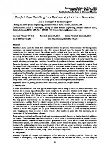
circles centred on the second blasthole in descending radii are approximate representations of the wavefronts for the p–wave, the s–wave and a hypothetical “crack front” respectively. The crack front velocity is assumed to be 0:34vs (see Section 2.3). The largest circle is centred on the first blasthole and represents the hypothetical “crack front” produced from that blasthole. It can be clearly seen that the predicted crack lengths are of the correct order. 4.2
Effect of free faces on crack development
MBM2D : EXAMPLES AND DISCUSSION Early crack development
The early fracture development in a five hole bench blast is shown in Figure 5. This is a plan view of the bench with a burden of 2.0 m, spacing of 1.8 m, at 4.98 ms after firing the first hole. The blasthole diameter was 65 mm (nb. the holes are shown oversize for clarity). The delay timing is 4.5 ms. The rock has a pwave velocity vp of 4667 m/s and an s-wave velocity vs of 2695 m/s. The static Young’s modulus is 47 GPa and the static tensile strength is 14.7 MPa. The bottom and side surfaces are non–reflecting (infinite) boundaries, the top surface is the crest of the bench. For this simulation we used a generic explosive which produced a peak pressure of 4.2 GPa with = 2:87.
Fig. 5: Fracturing from two blastholes – plan view
Cracks can be seen radiating from each of the blastholes with finer fragments appearing close to the holes. The simulation shows the initial stages of flexure at the crest line and clearly shows cracks that have originated at the crest coalescing with the cracks radiating outwards from the blastholes. On this figure we have superimposed four circles; the three smaller
Fig. 6: Cracks developing from free surfaces
The fact that many cracks can and do originate from the free faces is due to the tensile stresses arising from the reflection of waves as they travel back to the blasthole. This mechanism is clearly shown in Figure 6. The simulation is an elevation view of a single hole bench blast with 6 m burden, 14.5 m blasthole and an 11.5 m column (2.5 m toe charge) of the generic explosive mentioned earlier fired instantaneously (i.e. infinite VoD). The blasthole diameter was 300 mm. Contrary to the arguments of Persson (1990) (also see Section 1.1) it would appear that there is sufficient energy in this process to cause damage. However the simulation is two dimensional and plane strain so that the blasthole is in fact an “infinite” slot and cannot accommodate the refraction and diffraction that would occur around a true blasthole. We have not been able to satisfactorily adjust the powder factor to give realistic simulations for this geometry which is inherently and irrevocably three dimensional. 4.3
Effect of gas on crack development
To investigate the differences between the crack development due to stress effects alone and the effects
of the gas penetration into the cracks we have modelled blastholes with a blasthole liner and no stemming (resulting in stress effects and gas venting to the atmosphere) and blastholes with perfect stemming (resulting in gas effects and pressure relief only through cracks). The rock, explosive and blast design are similar to the blast designs discussed above. The results for a plan view are shown in Figures 7 and 8. In this simulation only the lefthand blasthole has been detonated in both cases.
prevent cracks running to the non–reflecting boundaries.)
Fig. 9: Single hole bench blast – not stemmed
Fig. 7: Bench blast (plan) – not stemmed
Fig. 10: Single hole bench blast – stemmed
Fig. 8: Bench blast (plan) – stemmed
It is immediately obvious that the fragmentation produced in the stemmed case is much finer than the unstemmed case. Heave velocities were also significantly greater for the stemmed case. (NB. The abrupt cutoff of the cracking region to the sides and the bottom of the problem is a restriction we imposed to
The equivalent results for an elevation view of a single hole bench blast are given in Figure 9 and Figure 10. In this case there was no toe charge resulting in an explosive column of 9 m. Similar conclusions about fragmentation and heave can be drawn to the plan view case. However in the unstemmed case large fragments are produced around the collar region which is an artefact of the 2D approximation of the blasthole as a slot which results in a large bending moment and artificial failure at the toe. In the stemmed case the “stemming” is modelled as if the original rock is in place. As mentioned there was no subdrill in either case and that has resulted in the uneven and rising
floor. There is evidence of considerable damage behind the final wall and below the blastholes in both cases. 4.4
Computational details
A complex code like MBM2D consumes considerable computing resources especially when attempting to simulate complete blasting events from initiation to rock on the ground.
Fig. 11: Bench blast at t=135 ms
As an example Figure 11 shows the results of the simulation discussed in Section 4.1 at 135 ms. The original mesh used 7337 elements, 3763 nodes. These numbers increase considerably throughout the calculation; in this particular case the number of elements almost doubled. In the original mesh the average element size was 0.4 m the smallest element being 0.02 m. Using a single processor Digital AlphaStation 250 (266 MHz (262 SPECfp92) with 128 MB RAM) running OpenVMS V6.2 this simulation ran at around 50 minutes cpu time per millisecond of problem time, the whole simulation to this point taking nearly 5 days. As a consequence of these long runtimes we are investigating different specialised computing solutions for running the 3D version. MBM2D will be used as an aid for understanding the complex blasting process. With the ability to model the dynamic and cooperative effects of the stress and gas and the ability to generate cracks and fragments we are in a position to analyse blasting dynamics in a more quantitative fashion than has hitherto been possible.
REFERENCES Barbour T.G., K.K. Wahi & D.E. Maxwell 1985. Prediction of fragmentation using CAVS. Fragmentation by Blasting. W.L. Fourney, R.R. Boade & L.S. Costin (Editors). Society for Experimental Mechanics. 1st Edn. pp. 158–172. Brinkmann J.R. 1987. Separating shock wave and gas expansion breakage mechanisms. Proc. 2nd Int. Symp. on Fragmentation by Blasting, Keystone, Colorado. pp. 6–15. Brinkmann J.R. 1987. An experimental study of the effects of shock and gas penetration in blasting. Proc. 3rd Int. Symp. on Fragmentation by Blasting, Brisbane, Australia. pp. 55–66. Ching E.S.C. 1994. Dynamic stresses at a moving crack tip in a model of fracture propagation. Phys. Rev. E. 49(4):3382–3388. Cundall P.A. 1980. UDEC – a generalised distinct element program for modelling jointed rock. Peter Cundall Assoc. Rep. Rept. PCAR-1-80, European Research Office, US Army, Contract DAJA37-79-C-0548 Cundall P.A. 1988. Formulation of a three–dimensional distinct element model — Part I. A scheme to detect and represent contacts in a system composed of many polyhedral blocks. Int. J. Rock Mech. Min. Sci. 25:107–116 ELFEN/explicit 1995, Rock eld Software , Swansea, Wales, Fourney W.L., D.B. Barker & D.C. Holloway 1983. Proc. 1st Int. Symp. on Fragmentation by Blasting, Lule˚a, Sweden. pp. 505–531. Gur Y., Z. Jaeger & R. Englman 1984. Fragmentation of rock by geometrical simulation of crack motion – I Engng. Fracture Mech. 20(56):783–800. Haghighi R., R.R. Britton & D. Skidmore 1988. Modelling gas pressure effects on explosive rock breakage. Int. J. Mining & Geological Engng. 6:73–79. Hallquist J. 1982. User’s manual for DYNA2D – an explicit two dimensional hydrodynamic finite element code with interactive rezoning and graphical display. Univ. California, LLNL, Report UCID–18756. Herget G. 1988. Stresses in rock. Rotterdam: Balkema Itasca Consulting Group Inc. 1995. PFC3D : Particle flow code in 3 dimensions, Vols. I, II and III, Minneapolis, Minnesota: ICG. Jorgenson G.K. & S.H. Chung 1987. Blast simulation – surface and underground with the SABREX model. CIM Bulletin, August, pp. 37–41. Kipp M.E. & D.E. Grady 1979. Numerical studies of rock fragmentation. Sandia Report SAND79–1582. Kirby I.J. & G.A. Leiper 1985. A small divergent detonation theory for intermolecular explosives. 8th Symposium (International) on Detonation, Office of Naval Research, Report NSWC MP 86-194, P. 176. Kuszmaul J.S. 1987. A new constitutive model for frag-
mentation of rock under dynamic loading. Proc. 2nd Int. Symp. on Fragmentation by Blasting, Keystone, Colorado. pp. 412–423. Kutter H.K. & C. Fairhurst 1971. On the fracture process in blasting. Int. J. Rock Mech. Min. Sci. 8:181–202 McHugh S. 1983. Crack extension caused by internal gas pressure compared with extension caused by tensile stress. 1983. Int. J. Fracture 21:163–176. Munjiza A. 1992. Discrete elements in transient dynamics of fractured media. Ph.D. Thesis. University of Wales, University College of Swansea, Wales, UK. Napier J.A.L. & A.P. Peirce 1995. Simulation of extensive fracture formation and interaction in brittle materials.
Proc. 2nd Int. Conf. on the Mechanics of Jointed and Faulted Rock, 10–14 April, Vienna, Austria, pp. 63–74. Nilson R.H., W.J. Proffer & R.E. Duff 1985. Modelling of gas–driven fractures induced by propellant combustion within a borehole. Int. J. Rock Mech. Min. Sci. 22:3– 19. Nilson R.H. 1988. Similarity solutions for wedge–shaped hydraulic fractures driven into a permeable medium by a constant inlet pressure. Int. J. Numer. Anal. Methods Geomech. 12:477–495. Nilson R.H. 1991. Dynamic modeling of explosively driven hydrofractures. J. Geophys. Res. 96, No. B11: 18.081– 18.100. Owen D.R.J., A. Munjiza & N. Bi´cani´c 1992. A finite element – discrete element approach to the simulatiuon of rock blasting problems. Proc. 11th Symp. on nite element methods in South Africa, Centre for Research in Computational and Applied Mechanics, Cape Town, 15–17 Jan. pp. 39–58. Paine A.S. & C.P. Please 1993. Asymptotic analysis of a star crack with a central hole. Int. J. Engng. Sci. 31:893– 898. Paine A.S. & C.P. Please 1994. A simple analytic model for the gas fracture process during rock blasting Int. J. Rock Mech. Min. Sci. 31:699–706. Persson P-A. 1990. Fragmentation mechanics. Proc. 3rd Int. Symp. on Fragmentation by Blasting, Brisbane, Australia. pp. 101–107. Preece D.S. & L.M. Taylor 1990. Proc. 3rd Int. Symp. on Fragmentation by Blasting, Brisbane, Australia. pp. 189–194. Preece D.S. 1993. Momentum transfer from flowing explosive gases to spherical particles during computer simulation of blasting induced rock motion. 9th Ann. Symp. on Explosives & Blasting Res. Society of Explosives Engineers, San Diego, California. pp. 251–260. Sarma K.S. 1994. Models for assessing the blasting performance of explosives. Ph.D. Thesis. JKMRC, University of Queensland, QLD, Australia. Simons J.W., D.R. Curran & T.H. Antoun 1995. A computer model for explosively induced rock fragmentation during
mining operations. 68th Ann. Minnesota Section SME & 56th Univ. Minnesota Mining Symp. Jan 24–26, Duluth, Minnesota. pp. 203–213. Song J. & K. Kim 1995. Numerical simulation of the blasting induced disturbed rock zone using the dynamic lattice network model. Proc. 2nd Int. Conf. on the Mechanics of Jointed and Faulted Rock, 10–14 April, Vienna, Austria, pp. 755–761. Taylor L.M. & D.P. Flanagan 1987. PRONTO2D – A two– dimensional transient solid dynamics program. Sandia Report. SAND86–0594. Taylor L.M. & D.S. Preece 1989. DMC – a rigid body motion code for determining the interaction of multiple spherical particles. Sandia Report. SAND88-3482. Timoshenko S.P. & J.N. Goodier 1970. Theory of elasticity. McGraw Hill. 3rd Edn Winzer S.R. & A.P. Ritter 1985. Role of stress waves and discontinuities in rock fragmentation. Fragmentation by Blasting. W.L. Fourney, R.R. Boade & L.S. Costin (Editors).Society for Experimental Mechanics. 1st Edn. pp. 11–23. Yang J. & S. Wang 1995. Study on fractal damage model of rock fragmentation. 2nd Int. Conf. on Engineering Blasting Technique. Nov 7–10, Kunming, China. pp. 288–293.